MPRT Protective Relay Test System - Maxtech
MPRT Protective Relay Test System - Maxtech
MPRT Protective Relay Test System - Maxtech

You also want an ePaper? Increase the reach of your titles
YUMPU automatically turns print PDFs into web optimized ePapers that Google loves.
<strong>MPRT</strong><br />
<strong>Protective</strong> <strong>Relay</strong> <strong>Test</strong> <strong>System</strong><br />
<strong>MPRT</strong><br />
Megger <strong>Protective</strong> <strong>Relay</strong> <strong>Test</strong> <strong>System</strong><br />
■<br />
■<br />
■<br />
■<br />
■<br />
The <strong>MPRT</strong> <strong>System</strong> consists of a ‘Power<br />
Box’, the TouchView Interface, and<br />
AVTS Software<br />
Unique new TouchView Interface (TVI)<br />
simplifies the manual testing of complex<br />
relays<br />
Ultra flexible output design provides up<br />
to four-phase voltage and current or eight<br />
phase current<br />
User specified configuration. Every system<br />
is made to order based on specific<br />
customer needs.<br />
Includes fully automated testing capability<br />
using AVTS Software (Version 2.0)<br />
DESCRIPTION<br />
The <strong>MPRT</strong> <strong>System</strong> is comprised of:<br />
• The ‘Power Box’<br />
• The TouchView Interface (TVI)<br />
• AVTS Software<br />
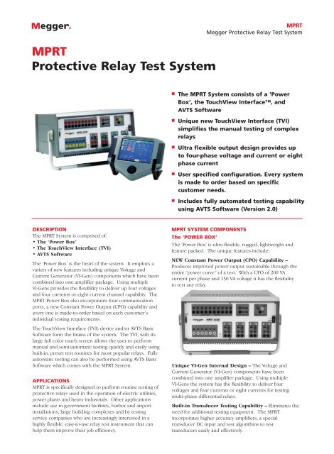
The ‘Power Box’ is the heart of the system. It employs a<br />
variety of new features including unique Voltage and<br />
Current Generator (VI-Gen) components which have been<br />
combined into one amplifier package. Using multiple<br />
Vi-Gens provides the flexibility to deliver up four voltages<br />
and four currents or eight current channel capability. The<br />
<strong>MPRT</strong> Power Box also incorporates four communication<br />
ports, a new Constant Power Output (CPO) capability and<br />
every one is made-to-order based on each customer’s<br />
individual testing requirements.<br />
The TouchView Interface (TVI) device and/or AVTS Basic<br />
Software form the brains of the system. The TVI, with its<br />
large full color touch screen allows the user to perform<br />
manual and semi-automatic testing quickly and easily using<br />
built-in, preset test routines for most popular relays. Fully<br />
automatic testing can also be performed using AVTS Basic<br />
Software which comes with the <strong>MPRT</strong> <strong>System</strong>.<br />
APPLICATIONS<br />
<strong>MPRT</strong> is specifically designed to perform routine testing of<br />
protective relays used in the operation of electric utilities,<br />
power plants and heavy industrials. Other applications<br />
include use in government facilities, harbor and airport<br />
installations, large building complexes and by testing<br />
service companies who are increasingly interested in a<br />
highly flexible, easy-to-use relay test instrument that can<br />
help them improve their job efficiency.<br />
<strong>MPRT</strong> SYSTEM COMPONENTS<br />
The ‘POWER BOX’<br />
The ‘Power Box’ is ultra flexible, rugged, lightweight and<br />
feature packed. The unique features include:<br />
NEW Constant Power Output (CPO) Capability –<br />
Produces improved power output sustainable through the<br />
entire “power curve” of a test. With a CPO of 200 VA<br />
current per phase and 150 VA voltage it has the flexibility<br />
to test any relay.<br />
Unique VI-Gen Internal Design – The Voltage and<br />
Current Generator (VI-Gen) components have been<br />
combined into one amplifier package. Using multiple<br />
VI-Gens the system has the flexibility to deliver four<br />
voltages and four currents or eight currents for testing<br />
multi-phase differential relays.<br />
Built-in Transducer <strong>Test</strong>ing Capability – Eliminates the<br />
need for additional testing equipment. The <strong>MPRT</strong><br />
incorporates higher accuracy amplifiers, a special<br />
transducer DC input and test algorithms to test<br />
transducers easily and effectively.
<strong>MPRT</strong><br />
Megger <strong>Protective</strong> <strong>Relay</strong> <strong>Test</strong> <strong>System</strong><br />
Includes Four Communication Ports – More built-in<br />
flexibility with a protocol choice of IEEE488, RS232, USB or<br />
Ethernet for high-speed download capability and upgrades<br />
via the internet.<br />
Here’s how easy it is<br />
From the Preset Menu Screen, the user simply selects the<br />
type of relay to be tested. Built-in test files are for a wide<br />
variety of protective relays, including Overcurrent,<br />
Differential, etc., see following figure.<br />
User Specified Configuration – Every system is made to<br />
order based on each customer’s testing requirements and<br />
budget, with an easy and flexible upgrade path.<br />
Output Capabilities for Worldwide Use – Even more<br />
built-in flexibility allows the user to choose from:<br />
• VI-Gen amplifiers rated at 30A @ 200 VA and convertible<br />
amplifiers rated at 300V or 5A @ 150 VA.<br />
• VI-Gen amplifiers rated at 15A @ 200 VA and convertible<br />
amplifiers rated at 150V or 5A @ 150 VA.<br />
THE TOUCHVIEW INTERFACE (TVI)<br />
Finally...an easier way to perform manual and semiautomatic<br />
relay testing. It’s all done via a unique hand<br />
held controller called the TouchView Interface (TVI). The<br />
most significant feature of the TVI is its ability to provide<br />
the user with a very simple way to manually test even the<br />
most complex relays being manufactured today.<br />
Manual operation is simplified through the use of a<br />
built-in computer operating system and the TouchView<br />
Interface, with a large color LCD touch-screen. The TVI<br />
eliminates the need for a computer when testing virtually<br />
all types of relays. Menu screens and function buttons are<br />
provided to quickly and easily select the desired test<br />
function .<br />
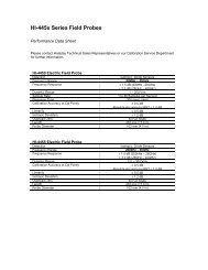
Preset <strong>Relay</strong> Select Screen<br />
As an example, touch the ‘Overcurrent’ button. An<br />
Overcurrent <strong>Test</strong> Menu Screen will be displayed showing<br />
all necessary functions needed to test that particular type<br />
of relay. Next, the user inputs the relay setting values that<br />
will be used to conduct the tests in terms any relay test<br />
technician can understand. Once the selection of setting<br />
has been made, the user then inputs the values commonly<br />
used with overcurrent relays, such as <strong>Relay</strong> Tap value and<br />
Time Dial value. These values are used when conducting<br />
the pickup and timing tests.<br />
To make it even better, the TVI has both IEEE and IEC<br />
time curve algorithms built-in. By entering the appropriate<br />
values in the setting screen, when the timing test is<br />
conducted, the test results will be automatically compared<br />
to the theoretical values from the time curve that was<br />
selected.<br />
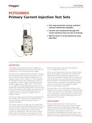
<strong>MPRT</strong> TouchView Interface TM<br />
Overcurrent <strong>Relay</strong> Setting Screen
<strong>MPRT</strong><br />
Megger <strong>Protective</strong> <strong>Relay</strong> <strong>Test</strong> <strong>System</strong><br />
As shown in the Overcurrent Setting screen, the IEEE Very<br />
Inverse time curve was selected. If the <strong>Test</strong> Multiple is<br />
changed, the appropriate theoretical trip time will change<br />
automatically.<br />
The TVI also has the ability to do even more complex tests<br />
and calculations. For example, the <strong>MPRT</strong> with three<br />
Voltage/Current Modules, can test single-phase, threephase<br />
open delta, and three-phase wye impedance relays<br />
using the Impedance relay test screen. The user simply<br />
selects different testing applications from a menu screen.<br />
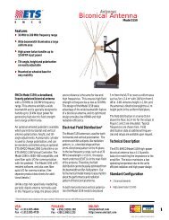
For instance, the Reach <strong>Test</strong> Screen for an impedance relay<br />
has been selected as shown below.<br />
For example, negative sequence under/over voltage, reverse<br />
phase, phase sequence, and current balance relays may be<br />
tested using the Voltage/Current manual test screen. In<br />
addition, manual control of up to 4 voltages and currents,<br />
or up to 8 currents is done using this test screen.<br />
Other devices such as auto-synchronizing, frequency<br />
sensitive devices and transducers also have their own<br />
individual manual test screens. There are no preset test<br />
routines. The user manually selects the parameter(s) to be<br />
set or adjusted using the touch-screen and ramps outputs<br />
using the control knob. Each test screen has a dynamic<br />
enable capability and will either automatically step from a<br />
prefault, to fault, to breaker trip, to reclose, or automatically<br />
ramp frequency at a preprogrammed Hz/Sec, or time for a<br />
given slip frequency, depending on which screen is in use.<br />
In the Manual Auto-Synchronizing <strong>Test</strong> Screen, the<br />
advanced closing time and closing angle are automatically<br />
done in the dynamic mode.<br />
Impedance Reach <strong>Test</strong> Screen<br />
It should be noted that not only does the display screen<br />
show metered values of voltage, current and phase angle,<br />
but it also displays the OHMS value where the relay picks<br />
up, (different formulas for calculating OHMS are selectable<br />
using the touch-screen and rotary knob).<br />
In addition, the zone associated with the result shown, the<br />
percent error and the type of fault simulated are displayed.<br />
The impedance test screen provides a pre-fault condition<br />
for those relays that require a pre-fault load prior to<br />
applying the fault. The test automatically determines values<br />
like reach, maximum angle of torque, and timing.<br />
Finally, for testing multi-zone relays, the user can select the<br />
Pulse-Ramp method to determine operating points without<br />
needing to defeat the other zone timers. Percent error<br />
criteria are input by the user to automatically evaluate the<br />
test result. Then, test results can be saved to the internal<br />
memory for later download and review.<br />
Also easily test relays not on the Preset Menu<br />
Other types of relays or devices not specifically listed in the<br />
Preset Menu Screen can be tested using one of the Manual<br />
<strong>Test</strong> screens.<br />
Manual Voltage/Current <strong>Test</strong> Screen<br />
In the Manual <strong>Test</strong> Screen shown below, the pre-selected<br />
outputs are set. The Green color indicates which output(s)<br />
have been selected. When the test is started by pressing<br />
the Start button, the selected output indicators will change<br />
colors from green to red indicating which outputs are<br />
energized. A vector graph indicates the relative phase<br />
angles of all of the outputs. All of the outputs are metered<br />
and displayed to provide real time verification of all of the<br />
selected outputs.<br />
Even perform manual transducer testing<br />
With the built-in transducer test screen, manually testing<br />
transducers has never been easier. The user simply selects<br />
from a pull-down menu, what type of transducer is being<br />
tested and enters information relative to the transducer's<br />
inputs and outputs. Upon starting the test, the test set<br />
automatically measures and calculates the % error of the<br />
device.
<strong>MPRT</strong><br />
Megger <strong>Protective</strong> <strong>Relay</strong> <strong>Test</strong> <strong>System</strong><br />
continuous real-time verification of the <strong>MPRT</strong> outputs, even<br />
when under automatic control.<br />
Transducer <strong>Test</strong> Screen<br />
In the above example, a three-phase, 3 Element Watt<br />
Transducer is being tested. The actual output watts is<br />
calculated based upon the measured values from the <strong>MPRT</strong><br />
into the transducer, and the transducer watts is calculated<br />
based upon the measured output voltage/current from the<br />
transducer. A %error is automatically calculated and<br />
displayed. A vector representation of the voltage and<br />
current outputs is also displayed.<br />
Use the File Manager to organize all test results<br />
The TVI has sufficient internal memory to save hundreds<br />
of test and result files. To manage the tests and results, the<br />
<strong>MPRT</strong> has a File Manager screen.<br />
Meter Display Screen<br />
Output values are displayed with a vector display, which<br />
shows the vector relationship between the output voltage<br />
and currents.<br />
User customized configuration<br />
The user may customize how the unit displays phase angles<br />
(0-360° Lead/Lag or ± 180°), and set default values of<br />
voltages, currents and frequency. The user may also select a<br />
language for prompting the operator. Six language choices<br />
are currently available, English, French, German, Spanish,<br />
Italian and Portuguese.<br />
File Manager Screen<br />
From any test screen, the user has access to the <strong>Test</strong> File<br />
Manager Screen. The user can give the test file/result file<br />
any name up to a maximum of 99 characters. Once saved,<br />
the user can recall the test and execute with the<br />
appropriate settings already set, or recall saved test results<br />
to download into the AVTS database for storage or for<br />
printing.<br />
TVI Default Setting Screen<br />
Other default settings include GPIB and IP addresses, Serial<br />
Port settings, Battery Simulator output and screen<br />
background colors.<br />
All output values are metered and displayed<br />
When under automatic computer control (with the AVTS<br />
software), the TVI becomes a meter display for all of the<br />
<strong>MPRT</strong> outputs. The metered values are displayed to provide
<strong>MPRT</strong><br />
Megger <strong>Protective</strong> <strong>Relay</strong> <strong>Test</strong> <strong>System</strong><br />
FEATURES AND BENEFITS<br />
■ Large Color LCD touch-screen display - The TVI<br />
features easy to use and read display provides manual<br />
control of the test set, and displays measured values of<br />
voltage, current, along with phase angle and frequency.<br />
Calculated values such as Ohms, Watts, VAR’s and Power<br />
Factor may also be displayed, depending on the test<br />
screen in use. Color contrasts accentuate vital<br />
information. This reduces human error and time in<br />
testing relays.<br />
■ Constant Output Power - The new <strong>MPRT</strong> employs new<br />
high powered Voltage-Current amplifiers (VI-Gen), which<br />
deliver maximum compliance voltage to the load<br />
constantly during the test. Constant output power in<br />
many cases eliminates the need to parallel current<br />
channels together to test high burden relays.<br />
■ High resolution and accuracy - The TVI has Metered<br />
outputs and a timer to provide extremely high accuracy.<br />
High accuracy extends testing capability to other devices<br />
such as transducers.<br />
■ Internal memory - The TVI provides storage of test<br />
set-up screens and test results. Reduces testing time and<br />
paper work.<br />
■ Steady-State and Dynamic testing capability - The<br />
<strong>MPRT</strong> provides, either through manual control or<br />
computer control, both steady-state and dynamic testing<br />
of protective relays. This includes programmable<br />
waveforms with dc offset and harmonics.<br />
■ Display screen prompts operator - The TVI features a<br />
display screen prompts the user with easy to use function<br />
buttons. Single button operation saves time in testing<br />
relays and minimizes human error.<br />
■ Display screen provides six different languages -<br />
The TVI display screen prompts the user in English,<br />
Spanish, Portuguese, French, Italian and German.<br />
■ Output current and voltage sinewaves are<br />
generated digitally - <strong>MPRT</strong> outputs do not vary with<br />
sudden changes in input voltage or frequency, which<br />
increases test accuracy and reduces testing time.<br />
■ Memory metering - Allows the user to set test currents<br />
and voltages faster. Reduces heating of device under test.<br />
■ Digital inputs and outputs - <strong>MPRT</strong> has 10<br />
programmable inputs, and 6 programmable outputs<br />
provide timing and logic operations in real-time with the<br />
output voltage and currents. Binary Inputs can be<br />
programmed, using Boolean logic, for more complex<br />
power system simulations. This provides a low cost,<br />
closed loop, power system simulator.<br />
■ Circuit breaker simulator - <strong>MPRT</strong>’s binary outputs<br />
provide programmable normally closed and normally<br />
open contacts to simulate circuit breaker operation for<br />
testing reclosing relays. Sequence of operation, timing,<br />
and lockout are easily tested.<br />
■ Performs transient tests - Perform acceptance or<br />
troubleshooting tests by replaying digitally recorded<br />
faults or EMTP/ATP simulations in the IEEE- C37.111,<br />
COMTRADE Standard format.<br />
■ Perform End-to-End tests - Using AVTS software and a<br />
portable GPS satellite receiver, the <strong>MPRT</strong> performs<br />
satellite-synchronized end-to-end dynamic or transient<br />
tests. Provides precisely synchronized testing of remotely<br />
located complex protection schemes.<br />
■ Wide-ranging output frequency - The output<br />
frequency of the current and voltage channels can be set<br />
for any frequency from dc to 10 kHz. Popular test<br />
frequencies such as 16.66, 25, 33, 50, 60, 100,120, 125,<br />
150, 180, 250, 300 and 400 Hz are easily set and<br />
controlled. Multi-purpose test system saves time and<br />
money.<br />
■ RS-232 serial port - The RS-232 port provides a<br />
computer interface to perform automatic testing.<br />
■ USB port - The USB port provides a computer interface<br />
to the test set for computers that do not have RS-232<br />
serial ports.<br />
■ Ethernet port - The Ethernet port provides a highspeed<br />
computer interface. This can be used to quickly<br />
download transient waveform data.<br />
■ IEEE-488GPIB - The IEEE-488 is an OEM preferred
<strong>MPRT</strong><br />
Megger <strong>Protective</strong> <strong>Relay</strong> <strong>Test</strong> <strong>System</strong><br />
interface for control of the unit. This interface is<br />
preferred, when using the unit with other IEEE-488<br />
devices. It can also provide high speed downloading of<br />
transient data.<br />
■ Universal input voltage - Operating from 90 to 264<br />
Vac, 50/60 Hz, the <strong>MPRT</strong> can use virtually any standard<br />
source in the world.<br />
■ Battery simulator - <strong>MPRT</strong>’s battery simulator provides<br />
dc output voltages of 24, 48, 125 and 250 Volts.<br />
Eliminates needing a separate dc source for providing<br />
logic voltage for microprocessor-based relays.<br />
■ Immediate error indication - Audible and visual<br />
alarms indicate when amplitude or waveforms of the<br />
outputs are in error.<br />
■ Modular design - Output modules plug-in and slide<br />
out easily for system re-configuration and maintenance.<br />
■ Ancillary Interface - Provides interface to other <strong>MPRT</strong><br />
units.<br />
■ <strong>MPRT</strong> Model 8430 - Provides up to 300 Volts rms. at<br />
150 VA and 30 Amps rms. at 200 VA per phase. Ample<br />
voltage for testing high instantaneous overvoltage relays.<br />
The current amplifier has high compliance voltage at low<br />
currents for testing ground overcurrent relays. When<br />
configured with four channels, the current amplifiers can<br />
be paralleled to provide a maximum of 120 Amperes at<br />
800 VA, for testing instantaneous overcurrent relays.<br />
With high VA output ratings, the unit can be used for<br />
testing a panel of relays.<br />
■ <strong>MPRT</strong> Model 8415 - Provides up to 150 Volts rms. at<br />
150 VA and 15 Amps rms. at 200 VA per phase. This<br />
lower cost unit is ideal for testing relays used with 1 Amp<br />
secondary CT’s. The current amplifier has high<br />
compliance voltage at low currents for testing ground<br />
overcurrent relays. When configured with four channels,<br />
the current amplifiers can be paralleled to provide a<br />
maximum of 60 Amperes at 800 VA, for testing<br />
instantaneous overcurrent relays. With high VA output<br />
ratings, the unit can be used for testing a panel of relays.<br />
Output Current Power Max V<br />
4 Amperes 200 VA 50.0 Vrms<br />
7.5 Amperes 200 VA 26.7 Vrms<br />
15 Amperes 200 VA 13.4 Vrms<br />
30 Amperes 200 VA 6.67 Vrms<br />
DC<br />
200 Watts<br />
With two currents in parallel:<br />
Output Current Power Max V<br />
8 Amperes 400 VA 50.0 Vrms<br />
15 Amperes 400 VA 26.7 Vrms<br />
30 Amperes 400 VA 13.4 Vrms<br />
60 Amperes 400 VA 6.67 Vrms<br />
With three currents in parallel:<br />
Output Current Power Max V<br />
12 Amperes 600 VA 50.0 Vrms<br />
22.5 Amperes 600 VA 26.7 Vrms<br />
45 Amperes 600 VA 13.4 Vrms<br />
90 Amperes 600 VA 6.67 Vrms<br />
With four currents in parallel:<br />
Output Current Power Max V<br />
16 Amperes 800 VA 50.0 Vrms<br />
30 Amperes 800 VA 26.7 Vrms<br />
60 Amperes 800 VA 13.4 Vrms<br />
120 Amperes 800 VA 6.67 Vrms<br />
With two currents in series, the compliance voltage doubles to<br />
provide 4.0 Amperes at 100 Volts.<br />
Model 8415<br />
SPECIFICATIONS<br />
Input Power<br />
90 to 264 Volts AC, 50/60 Hz, 1920 VA.<br />
Outputs<br />
All outputs are independent from sudden changes in line voltage<br />
and frequency. This provides stable outputs not affected by sudden<br />
changes in the source. All outputs are regulated so changes in load<br />
impedance do not affect the output. Each output module consists<br />
of one current amplifier, and a voltage amplifier. The voltage<br />
amplifier may be converted to a current source. Therefore, one<br />
amplifier module may be used to test current differential relays,<br />
including harmonic restraint.<br />
Output Current<br />
The following specifications cover both Model 8430 and Model<br />
8415 modules. Outputs are rated with the following:<br />
Model 8430<br />
Per phase:<br />
Power Curve for Model 8430<br />
Per phase:<br />
Output Current Power Max V<br />
4 Amperes 200 VA 50.0 Vrms<br />
7.5 Amperes 200 VA 26.7 Vrms<br />
15 Amperes 200 VA 13.4 Vrms<br />
DC<br />
200 Watts<br />
With two currents in parallel:<br />
Output Current Power Max V<br />
8 Amperes 400 VA 50 Vrms<br />
15 Amperes 400 VA 26.7 Vrms<br />
30 Amperes 400 VA 13.4 Vrms<br />
With three currents in parallel:<br />
Output Current Power Max V<br />
12 Amperes 600 VA 50 Vrms<br />
22.5 Amperes 600 VA 26.7 Vrms<br />
45 Amperes 600 VA 13.4 Vrms
<strong>MPRT</strong><br />
Megger <strong>Protective</strong> <strong>Relay</strong> <strong>Test</strong> <strong>System</strong><br />
With four currents in parallel:<br />
Output Current Power Max V<br />
16 Amperes 800 VA 50 Vrms<br />
30 Amperes 800 VA 26.7 Vrms<br />
60 Amperes 800 VA 13.4 Vrms<br />
With two currents in series, the compliance voltage doubles to<br />
provide 4.0 Amperes at 100 Volts.<br />
AC Voltage Output<br />
The following specifications cover both the Model 8430 and 8415<br />
modules. Outputs are rated with the following Ranges:<br />
Model 8430<br />
Power Curve for Model 8415<br />
Per phase:<br />
Output Volts Power Max I<br />
30 Volts 150 VA 5 Amps<br />
150 Volts 150 VA 1 Amp<br />
300 Volts 150 VA 0.5 A<br />
DC<br />
150 Watts<br />
With two voltages in series:<br />
Output Volts Power Max I<br />
60 Volts 300 VA 5 Amps<br />
300 Volts 300 VA 1 A<br />
600 Volts 300 VA 0.5 A<br />
With three converted sources in parallel:<br />
Output Current Power Max V<br />
0 - 15Amperes 450 VA 30 Vrms<br />
Model 8415<br />
Per phase:<br />
Output Volts Power Max I<br />
30 Volts 150 VA 5 Amps<br />
150 Volts 150 VA 1 Amp<br />
DC<br />
150 Watts<br />
With two voltages in series:<br />
Output Volts Power Max I<br />
60 Volts 300 VA 5 Amps<br />
300 Volts 300 VA 1 A<br />
With three converted sources in parallel:<br />
Output Current Power Max V<br />
15Amperes 450 VA 30 Vrms<br />
Battery Simulator<br />
The battery simulator provides the following DC output:<br />
24, 48, 125 or 250 Volts at 60 Watts. Voltage output is controlled<br />
via the Touch-View Interface, or through AVTS software.<br />
Metering<br />
Measured output quantities such as AC Amperes, AC Volts, DC<br />
Volts or DC Amperes, and Time may be simultaneously displayed<br />
on the large, variable contrast, color LCD screen. The memory<br />
feature of the metering provides fast and accurate preset of test<br />
values. The AC and DC outputs display the approximate<br />
voltage/current output prior to initiation of the outputs. This<br />
provides a fast, easy method for preset of outputs. Other values<br />
that may be displayed, depending on which test screen is in view,<br />
are frequency, Ohms, Watts, VARS and Power Factor. All accuracies<br />
stated are from 10 to 100% of the range at 50/60 Hz.<br />
AC/DC Output Amperes<br />
Accuracy: ±0.05% typical, 0.1 % or ± least significant digit,<br />
which ever is greater, guaranteed.<br />
Resolution: .001/.01<br />
Measurements: True RMS<br />
AC/DC Output Volts<br />
Accuracy: ±0.05% typical, 0.1 % or ± least significant digit,<br />
which ever is greater, guaranteed.<br />
Resolution: .001/.01/.1<br />
Measurements: True RMS<br />
Phase Angle<br />
Ranges 0 to 359.9 degrees Lead/Lag<br />
Accuracy: ±0.02° typical<br />
0.1° Guaranteed<br />
Frequency:<br />
The output modules provide a variable frequency output with<br />
the following ranges and accuracy.<br />
Ranges<br />
DC<br />
0.001 to 99.999 Hz<br />
100.01 to 999.99 Hz<br />
1000.1 to 9999.9 Hz<br />
Resolution: .001 Hz<br />
Frequency Accuracy:<br />
0.5 ppm typical<br />
1.0 ppm at 25° C, ±5° C<br />
5.0 ppm 0° to 50° C<br />
Total Harmonic Distortion:<br />
Less than 0.1 % typical,<br />
2 % maximum at 50/60 Hz.<br />
Power<br />
The Watts displayed is the calculated value based on the displayed<br />
formula. Seven different formulas are available.<br />
Range and Resolution 0 to 15 kW, with 0.1 % resolution<br />
Accuracy: ± .5 % of VA ±1 least significant digit<br />
The DC IN input terminals:<br />
DC IN Volts<br />
DC IN Amperes<br />
Range: 0 to ±10 V DC 0 to ±mA DC<br />
1 to ±mA DC<br />
Accuracy: ±0.02% Accuracy: ±0.02 %<br />
Resolution: .001/.01/.1 Resolution: .0001/.001<br />
Measurements: Average Measurements: Average<br />
Timer-Monitor<br />
The Timer-Monitor (Binary Inputs) are designed to monitor and<br />
time-tag inputs, as a sequence of events recorder. In addition, the<br />
binary input controls enable the user to perform logic AND/OR<br />
functions on the inputs, and conditionally control the binary
<strong>MPRT</strong><br />
Megger <strong>Protective</strong> <strong>Relay</strong> <strong>Test</strong> <strong>System</strong><br />
output relays to simulate circuit breaker, trip, reclose and carrier<br />
control operation in real-time. The Timer function displays in<br />
Seconds or Cycles, with the following range and resolution:<br />
Seconds: 0.0001 to 9999.9 (Auto Ranging)<br />
Cycles: 0.01 to 99999.9 (Auto Ranging)<br />
Accuracy: ±1 least significant digit or ±.001% of reading,<br />
whichever is greater.<br />
Binary Inputs- Start/Stop/Monitor Gates:<br />
10 identical, independent, galvanically isolated, Start/Stop or<br />
Monitor circuits are provided. To monitor operation of relay<br />
contacts or trip SCR, a continuity light is provided for each input<br />
gate. Upon sensing continuity the lamp will glow and a tone<br />
generator will sound. In addition to serving as Timer/Monitor<br />
inputs, the Binary Inputs may be programmed to trigger binary<br />
output sequence(s). Binary Inputs can also be programmed using<br />
Boolean logic for more complex power system simulations.<br />
Input Rating: up to 300 V AC/DC<br />
Binary Output <strong>Relay</strong>s:<br />
6 identical, independent, galvanically isolated, output relay<br />
contacts accurately simulate relay or power system inputs to<br />
completely test relays removed from the power system. Binary<br />
outputs simulate normally open/normally closed contacts for<br />
testing breaker failure schemes. Outputs can be configured to<br />
change state based on binary input logic (Boolean logic is available<br />
for more complex simulations), or a specified time delay after a<br />
logic input condition.<br />
Contact Rating: Up to 400 Volts peak, AC/DC, 1 Amp continuous,<br />
8 Amps Max.<br />
Waveform Generation<br />
Each output channel can generate a variety of output waveforms<br />
such as: DC; sinewave; sinewave with percent harmonics at various<br />
phase angles; half waves; square waves with variable duty cycles;<br />
exponential decays; periodic transient waveforms from digital fault<br />
recorders, relays with waveform recording capability or EMTP/ATP<br />
programs, which conform to the IEEE C37.111 COMTRADE<br />
standard format. In addition, each output channel has input BNC<br />
connector for amplification of external analog signals.<br />
Waveform Storage<br />
Each output channel can store waveforms for playback on<br />
command. End-to-end playback of stored waveforms is possible,<br />
when triggered externally by a GPS receiver. Each channel can<br />
store up to 256,000 samples.<br />
Protection<br />
Voltage outputs are protected from short circuits and prolonged<br />
overloads. Current outputs are protected against open circuits<br />
and overloads.<br />
Ancillary Interfaces<br />
On the back panel of the <strong>MPRT</strong> are the RS-232, USB, Ethernet,<br />
IEEE-488 GPIB, Trigger In, Trigger Out, Clock In, and Clock Out.<br />
Temperature Range<br />
Operating: 32 to 122° F (0 to 50° C)<br />
Storage: -13 to 158° F (-25 to 70° C)<br />
Relative Humidity: 5 - 90% RH, Non-condensing<br />
Dimensions<br />
Unit Enclosure<br />
17.2 W x 8.75 H x 18.5 D* in. (430 W x 218 H x 463 D mm)<br />
*Includes 2.5” depth of floor stand-offs<br />
Weight<br />
Weight varies depending on the number of output modules in the<br />
system. The weights shown below are for a complete three-phase<br />
test system.<br />
Model 8415: Model 8430:<br />
45 lb. (20.4 kg) 45 lb. (20.4 kg)<br />
Safety, EMC, RFI and ESD Conformance<br />
IEC 61010-1, Amendments 1 and 2, EN 50081-2, EN 50082-2,<br />
EN 55014, EN 55011, EN 60555-2, EN 61000-4-2,<br />
IEC 61000-4-2/3/4/5/6/8/11.<br />
Shock, Vibration and Temperature<br />
To simulate the worst field conditions the unit was tested in<br />
accordance with Military Standard MIL-STD-810 for temperature,<br />
humidity, shock, and vibration.<br />
Enclosure and Transit Cases<br />
The unit comes mounted in a rugged enclosure for field<br />
portability. A padded soft-sided carry case is provided with the<br />
unit. The soft-sided carry case protects the unit from light rain<br />
and dust. The padded sides provide protection while in transit.<br />
An optional hard-sided transit case is available. The robust design<br />
of the optional hard-sided transit case provides protection when<br />
transporting the unit over rugged terrain and long distances.<br />
AVTS<br />
Advanced Visual <strong>Test</strong> Software Version 2.0<br />
DESCRIPTION<br />
AVTS is a Microsoft ® Windows ® 98/ME/NT4.0/2000/XP ®<br />
software program designed to manage all aspects of<br />
protective relay testing using the new Megger <strong>MPRT</strong> or<br />
older PULSAR relay test sets. More flexibility has been<br />
added as well as some new and powerful features. AVTS<br />
comes in three different levels:<br />
■ Basic<br />
■ Advanced<br />
■ Professional<br />
Every <strong>MPRT</strong> unit comes with AVTS Basic.<br />
The Basic version includes Online Vector and Ramp controls,<br />
with the ability to import, save and execute test modules. In<br />
addition, the Basic version includes enhanced <strong>Relay</strong> <strong>Test</strong><br />
Wizards, including new wizards not previously available.<br />
The Advanced version includes the <strong>Test</strong> Editor, Waveform<br />
Digitizer and basic programming Tools for creating and<br />
editing test modules.<br />
The Professional version includes all of the features of the
<strong>MPRT</strong><br />
Megger <strong>Protective</strong> <strong>Relay</strong> <strong>Test</strong> <strong>System</strong><br />
Basic and Advanced versions plus some new and powerful<br />
features. It includes the DFR Waveform Viewer and editor,<br />
End-to-End test files and the new One-Touch <strong>Test</strong> TM feature.<br />
APPLICATIONS<br />
Using the Online Ramp Control, traditional steady-state<br />
tests are easily performed with AVTS by simply applying<br />
test quantities to the device under test and automatically<br />
ramping the current, voltage, phase angle or frequency.<br />
Using either the Online Ramp or Vector Controls, Dynamic<br />
tests can easily be performed. The dynamic test includes<br />
setting a prefault condition and allowing the software to<br />
automatically test/search for the operating characteristic of<br />
the relay by selecting one of several available methods.<br />
Using <strong>Test</strong> Wizards or <strong>Test</strong> Modules, Fault types are<br />
selected from a pull-down window.<br />
Operating characteristics for virtually any type of relay are<br />
easily defined using Mho circles, Lenticular, Tomato<br />
characteristics, or a combination of lines, line and slope,<br />
time and amplitude, calculated value or theoretical object<br />
(a time-current curve may be scanned into the program<br />
using the digitizer feature in either the Advanced or<br />
Professional versions of AVTS).<br />
The AVTS <strong>Test</strong> Screen enables you to view test values<br />
(both theoretical and actual) on one screen. For example,<br />
the figure above shows test values, both theoretical and<br />
actual results, all on one screen.<br />
The following chart provides an easy reference showing<br />
the features of each version of AVTS Software:<br />
Feature<br />
Online Vector Control<br />
Online Ramp Control<br />
Import, Save, and<br />
Execute <strong>Test</strong> Modules<br />
<strong>Test</strong> Report Generator<br />
DFR Playback<br />
Fault Calculator<br />
Overcurrent Wizard<br />
Over/Under Voltage Wizard<br />
Frequency Wizard<br />
Differential Wizard<br />
Distance Wizard<br />
Synchronizing Wizard<br />
Directional Wizard<br />
<strong>Test</strong> Editor<br />
Waveform Digitizer<br />
Basic Programming Tool<br />
Import Aspen <strong>Relay</strong><br />
Database ®<br />
DFR Waveform Viewer<br />
and Playback<br />
End-to-End <strong>Test</strong><br />
One-Touch <strong>Test</strong><br />
Description<br />
The Online Vector Control allows the user to have direct control<br />
of the <strong>Relay</strong> <strong>Test</strong> <strong>System</strong>. Up to sixteen vector states may be<br />
created and sequenced back through the test system.<br />
Preramp (prefault), Ramp 1 and Ramp 2 are available for use to<br />
be played back through the test system. Automatically Ramp or<br />
Pulse Ramp outputs. Enable timer control with either ramp.<br />
Import relay test files and execute selected tests. Save results to<br />
built-in Microsoft Access compatible data base, and print results.<br />
Print reports in AVTS format or export to Microsoft Word to<br />
customize using company logo or standard company format.<br />
Import and execute relay test modules, which contain DFR<br />
playback files created using the DFR Waveform Viewer Tool.<br />
Calculate fault values for Ø-Ø, Ø-N, Ø-Ø-N and 3 Ø faults. Use<br />
line voltage, line Z and angle, relay volts and angle, relay amps<br />
and Z0/Z1.<br />
Provides automatic testing of overcurrent relays, including timing<br />
characteristic using IEEE / IEC formulas, DC target and seal-in<br />
tests.<br />
Provides automatic testing of over and under voltage relays,<br />
including timing characteristic and DC target and seal-in tests.<br />
Provides automatic testing of over and under frequency relays,<br />
including timing characteristic and DC target and seal-in tests.<br />
Provides automatic testing current differential relays, including<br />
2nd, 3rd and 5th harmonic restraint tests on transformer<br />
differential relays.<br />
Provides automatic testing of distance relays. Ø-Ø, Ø-G, and 3<br />
Phase faults are available. <strong>Test</strong> result graphics are displayed in an<br />
R X plane.<br />
Provides automatic testing of synchronizing relays<br />
Provides automatic testing capability of directional elements.<br />
Provides editing tools for modifying test modules.<br />
Provides digitizing tool for digitizing waveforms and trip curves.<br />
Provides control tool in the <strong>Test</strong> Editor. Basic programs can be<br />
written using the test system command set for special testing<br />
applications. This includes building complex waveforms up to the<br />
50th harmonic.<br />
Capability to import relay settings directly from Aspen <strong>Relay</strong><br />
Database ®<br />
Import, view, modify and replay Digital Fault Recordings or<br />
EMTP/ATP simulations that are in the COMTRADE file format.<br />
“End-to-End” testing is used to describe the testing of an entire<br />
line protection scheme. This includes all protective relays,<br />
interface equipment, and any communication equipment.<br />
<strong>Test</strong> Editor control tool, used in conjunction with specific Megger<br />
<strong>Test</strong> Modules, to download relay settings (into AVTS) from<br />
microprocessor based relays for full automatic one-touch testing.<br />
Software<br />
Basic Advanced Professional<br />
• • •<br />
• • •<br />
• • •<br />
• • •<br />
• • •<br />
• • •<br />
• • •<br />
• • •<br />
• • •<br />
• • •<br />
• • •<br />
• • •<br />
• • •<br />
• •<br />
• •<br />
• •<br />
• •<br />
•<br />
•<br />
•
<strong>MPRT</strong><br />
Megger <strong>Protective</strong> <strong>Relay</strong> <strong>Test</strong> <strong>System</strong><br />
AVTS BASIC VERSION<br />
There are three versions of AVTS software. The Basic<br />
version is included with each <strong>MPRT</strong> unit. The Advanced and<br />
Professional versions are optional. The Basic version<br />
includes online Vector and Ramp controls, relay testing<br />
wizards for most types of relays, the ability to import, save<br />
and execute relay specific test modules created either by<br />
Megger or someone else with either an Advanced or<br />
Professional version of AVTS 2.0. Basic can also playback a<br />
DFR file created using the Professional version of AVTS.<br />
The following describes the features of the Basic version of<br />
AVTS 2.0.<br />
Aux Contact Check Box- will close an “aux” binary<br />
output contact conditional with change from one vector<br />
state to another.<br />
Edit Custom Prefix Command- available for each vector<br />
state and allows entry of a formula, <strong>Relay</strong> <strong>Test</strong> <strong>System</strong><br />
syntax, or other controlling variable for that selected vector<br />
state.<br />
Zoom- enlarges the polar vector diagram to the full<br />
dimensions of the dialog box.<br />
Favorites - save a single vector, or a set of multiple vectors,<br />
with all the parameters to a desired name for recall at a<br />
later time in the Online Vector Control (Basic Version) or<br />
the <strong>Test</strong> Editor Vector Control (requires Advanced version).<br />
Save to the name placed in the edit field will retain only<br />
the selected vector(s) in the vector list. The Edit Customs<br />
Prefix Commands are saved along with the generator<br />
parameters.<br />
Set to Variables - selection replaces the numeric values<br />
for all the vector parameters to known default variable<br />
names. This function is more commonly used for the<br />
Vector Control used within a test development in the <strong>Test</strong><br />
Editor (Advanced Version), where the variable names are<br />
given values in the Settings Screen, Variable Watch edit field<br />
(a powerful programming tool in the Advanced version) in<br />
the <strong>Test</strong> Screen, or in another control in the <strong>Test</strong> Editor<br />
(Advanced version) Screen prior to the Vector control.<br />
Online Vector Control<br />
The Online Vector Control, launched from the AVTS<br />
Tools menu item, allows the user to have direct control of<br />
the <strong>Relay</strong> <strong>Test</strong> <strong>System</strong>. Up to sixteen vector states may<br />
be created and played back through the <strong>Relay</strong> <strong>Test</strong> <strong>System</strong>.<br />
A timer control is available to enable starting the <strong>Relay</strong><br />
<strong>Test</strong> <strong>System</strong> timer at the execution of any one of the vector<br />
states. The timer stop is typically controlled by an action<br />
from one of a device’s outputs connected to the<br />
appropriate <strong>Relay</strong> <strong>Test</strong> <strong>System</strong> timer stop gate. The default<br />
view of the Online Vector Control remains visible during all<br />
use of the control.<br />
For manual ramping of amplitudes and phases, a gang<br />
control is available through the selection of the vectors<br />
(<strong>Relay</strong> <strong>Test</strong> <strong>System</strong> amplifiers) to be controlled. The<br />
vectors to be controlled in gang are selected by using the<br />
mouse to grab and alter the vector(s) parameters. Vector<br />
selection is made by clicking on a vector channel name to<br />
highlight that vector with its parameters. Should it be<br />
desired to simultaneously control more than one vector,<br />
the user will need to click on the wanted vectors while<br />
holding the keyboard Ctrl key down to highlight all of the<br />
selected vectors. The user may then select from the<br />
“Dragging Parameters” box whether the amplitudes<br />
and/or phases of the selected vectors are to be active.<br />
Once selected, the user can grab the tip of any of the<br />
selected vectors in the polar graph and, while holding the<br />
left mouse button down, move the vector(s). The values<br />
of the vector(s) will change graphically and numerically,<br />
and simultaneously pass the new values directly to the<br />
corresponding <strong>Relay</strong> <strong>Test</strong> <strong>System</strong> amplifiers. Some other<br />
unique features are;<br />
Online Ramp Control<br />
The Online Ramp Control, launched from the AVTS<br />
Tools menu item, allows the user to have direct real time<br />
control of the <strong>Relay</strong> <strong>Test</strong> <strong>System</strong>. This control is very similar<br />
to the Online Vector Control. However, where the vector<br />
control sequences through up to 16 different states, the<br />
Ramp Control provides automatic ramping of selected<br />
outputs to do pick-up or drop outs tests of amplitude,<br />
phase angle or frequency. Pre-ramp, Ramp 1 and Ramp 2<br />
are available for use to be played back through the <strong>Relay</strong><br />
<strong>Test</strong> <strong>System</strong>. A timer control is available to enable starting<br />
the <strong>Relay</strong> <strong>Test</strong> <strong>System</strong> timer at the execution of either of<br />
the ramp states. The timer stop is typically controlled by<br />
an action from one of a device’s outputs connected to the<br />
timer stop gate.
<strong>MPRT</strong><br />
Megger <strong>Protective</strong> <strong>Relay</strong> <strong>Test</strong> <strong>System</strong><br />
Similar to Online Vector Control, Online Ramp Control<br />
provides manual ramping of amplitudes and/or phases.<br />
The gang control is similar through the selection of the<br />
vectors (<strong>Relay</strong> <strong>Test</strong> <strong>System</strong> amplifiers) to be controlled.<br />
The outputs to be controlled in gang are selected by using<br />
the mouse to grab and alter the parameters (see Online<br />
Vector Control for more details). Another feature of the<br />
Online Ramp Control is the ability to do Pulse Ramping.<br />
One advantage of Pulse Ramping is the capability to<br />
determine reach points on multi-zone distance relays<br />
without needing the defeat the zone timing elements. For<br />
relays which require a prefault load condition prior to<br />
applying a fault value, the Online Ramp Control has a Preramp<br />
(Pre-fault) state. This feature allows the user to apply<br />
the appropriate load values before Pulse Ramping begins.<br />
After applying a fault value the Ramp Control returns to the<br />
Pre-ramp state before the next value is applied. Many of the<br />
same features in the Online Vector Control are also<br />
available in the Ramp Control, such as the Zoom, Set<br />
Variables and Favorites.<br />
<strong>Test</strong> Wizards<br />
All versions of AVTS software come with test wizards. The<br />
wizards walk the user through a step by step procedure to<br />
create a relay specific test(s). Wizards are available for the<br />
most common types of relays such as, Overcurrent,<br />
Over/Under Voltage, Frequency, Differential, Distance,<br />
Synchronizing and Directional. The following is a brief<br />
description of each test wizard.<br />
Frequency Wizard - Provides automatic pickup and timing<br />
tests for over or under frequency relays. A test report will<br />
provide pass/fail information of the test results based on<br />
user input.<br />
Typical Under Frequency <strong>Relay</strong> Pickup test<br />
Differential Wizard - Perform automatic winding pickup,<br />
differential characteristic (slope) test and harmonic restraint<br />
tests. In the above figure, the test result screen was resized<br />
using the mouse and the windows drag and drop feature.<br />
Overcurrent Wizard - Provides automatic pickup,<br />
instantaneous pickup and timing. IEEE and IEC time curve<br />
algorithms are provided for automatic evaluation of the<br />
results. Digitized time curves for various electromechanical<br />
overcurrent relays are also available. For North American<br />
relays, a dc target and seal-in test is available. A test report<br />
will provide pass/fail information of the test results.<br />
Resized Differential Slope <strong>Test</strong> Screen<br />
This allows the operator to more closely examine test points<br />
and results. The user may then generate a test report with<br />
the test results showing pass/fail based upon input by the<br />
user.<br />
Timing <strong>Test</strong> of Overcurrent <strong>Relay</strong><br />
Over/Under Voltage Wizard - Provides automatic pickup<br />
and timing. A test report will provide pass/fail information<br />
of the test results based on user input.<br />
Distance Wizard - Perform automatic reach, max angle of<br />
torque and characteristic tests on single phase, three phase<br />
open delta or three phase Y connected relays. User may<br />
choose between fixed voltage and vary current or fix<br />
current and vary voltage. In addition, the user may select<br />
mho, lens, tomato or other basic distance characteristics<br />
using a pull-down menu. The test report will provide<br />
pass/fail information based upon user data input.
<strong>MPRT</strong><br />
Megger <strong>Protective</strong> <strong>Relay</strong> <strong>Test</strong> <strong>System</strong><br />
This example has the Organization tree by Region, then<br />
Substation, then Line, then panel and finally the relay in the<br />
panel. The relays installed are then listed under that<br />
location. As part of the installation process of AVTS, the<br />
default Organization tree comes with three levels and may<br />
either be accepted or a new Organization tree may be edited<br />
with up to five levels.<br />
In addition to showing the location of the relays in your<br />
system, it can also be used to look at the historical test<br />
records of any individual relay. By clicking on the box, it<br />
expands the selected relay’s test history.<br />
Typical Phase to Phase Characteristic <strong>Test</strong><br />
Synchronizing Wizard - Provides automatic closing angle<br />
test and timing. A test report will provide pass/fail<br />
information of the test results based on user input<br />
Directional Wizard - Perform automatic pickup test on<br />
directional elements. A report will provide test result.<br />
Import, Save, Execute <strong>Test</strong> Modules<br />
AVTS Basic users can import test modules generated by<br />
Megger, or someone else using the Advanced or<br />
Professional versions of AVTS. The user can execute the<br />
tests, save results and print results. In addition, users can<br />
playback a Digital Fault Record, which has been generated<br />
by the Professional version of AVTS 2.0.<br />
Database<br />
The database is Windows Access compatible. Data is saved<br />
in a conventional tree format to facilitate ease of use.<br />
The following figure illustrates the AVTS navigator <strong>Relay</strong> tab<br />
when AVTS is opened for use. The <strong>Relay</strong> has been<br />
expanded to illustrate the Organization.<br />
The Organization is the method used to geographically<br />
locate the relays installed in this database.<br />
<strong>Test</strong> History for IAC77 <strong>Relay</strong><br />
<strong>Test</strong> Reports<br />
Individual test results can be viewed by double clicking on<br />
the desired result file. The test report can either be printed,<br />
or exported to Microsoft Word for user customized report<br />
generation using company logo, company standard format<br />
etc.<br />
Fault Calculator<br />
The Fault Calculator allows the user to automatically<br />
calculate fault quantities for phase-to-phase, phase-toground,<br />
phase-to-phase-to-ground and three-phase faults.<br />
The user inputs variables for: line voltage, line Z with angle,<br />
relay volts with angle, relay amps and Z0/Z1. The Z0/Z1<br />
system impedance ratio is applied to both the source Z and<br />
the line Z for all faults which include ground.<br />
AVTS ADVANCED VERSION<br />
The Advanced version includes all of the features<br />
previously described for the Basic version. In addition, it<br />
includes the very powerful <strong>Test</strong> Editor, the Waveform<br />
Digitizer, Basic Programming Tool and generic preconstructed<br />
relay test modules. Advanced users can also<br />
playback a DFR file created by someone using the<br />
Professional version of AVTS. The following describes the<br />
additional features of the Advanced version of AVTS 2.0.<br />
<strong>Test</strong> Editor<br />
The real power of AVTS is in the <strong>Test</strong> Editor window. No<br />
more complicated test macros to write or edit. Instead, the<br />
user selects from a variety of icons representing various<br />
test macro functions. For example, in the following Figure,<br />
certain icons are selected and connected using the mouse.<br />
The software takes care of the rest. No more theoretical<br />
characteristic macros to write either. Simply click on the<br />
appropriate icon and drop into the test editor window.<br />
What may have taken days or weeks to “write” using basic<br />
programming now takes only minutes!
<strong>MPRT</strong><br />
Megger <strong>Protective</strong> <strong>Relay</strong> <strong>Test</strong> <strong>System</strong><br />
<strong>Test</strong> Editor Window<br />
In addition, the test wizards automatically assemble and<br />
connect the appropriate icons for you. All you need to do<br />
is edit the appropriate control function to meet your<br />
specific needs. For example, using a right-mouse click on<br />
the Ramp Control Icon (in the <strong>Test</strong> Editor work screen),<br />
and then clicking on the Increment button, the user is able<br />
to adjust the increment value of each current increment for<br />
a pickup test.<br />
Connections Editor Screen provides relay test connections details<br />
icons for the user to define each as an image bitmap to<br />
import into the connection editor screen. This can include<br />
schematic internal diagrams of the relays, or other helpful<br />
information. In the above figure, a digital picture of the<br />
older AVO Pulsar test set has been used to illustrate how to<br />
connect to the relay to be tested. Pictures of other test sets<br />
may also be used for illustration.<br />
Waveform Digitizer<br />
The AVTS Waveform Digitizer Tool enables the user to<br />
digitize waveforms and export them to a COMTRADE *.cfg<br />
and *.dat files for playback through the <strong>Test</strong> <strong>System</strong>.<br />
Waveforms from old strip chart recorders, hand drawn<br />
waveforms, and waveforms created by oscillographic<br />
functions of the modern microprocessor and numerical<br />
relays; any waveform that can be represented in a *.bmp<br />
format can be digitize. In addition, electromechanical relay<br />
analog time curves, that do not fit numerical algorithms,<br />
can be scanned into AVTS. The digitizer can be used to<br />
create a virtual time curve to be used in the timing test. For<br />
example, AVTS software comes with numerous analog<br />
curves already digitized and ready for use.<br />
Adjusting Ramp Control- Current Increment<br />
Connections Editor<br />
A picture is worth a thousand words. It seems like modern<br />
relays need a thousand connections today, so the<br />
Connections Editor is ideal to show how to connect the test<br />
system to the device under test. Powerful graphic tools are<br />
available to show test connections (see following Figure).<br />
The Connections Images toolbar contains ten available<br />
Westinghouse CO-9 Digitized Time-Current Curves
<strong>MPRT</strong><br />
Megger <strong>Protective</strong> <strong>Relay</strong> <strong>Test</strong> <strong>System</strong><br />
Basic Programming Tool<br />
The Basic Programming Tool provides a means to either<br />
import older test macros into AVTS and execute legacy test<br />
files, or to send the test system syntax commands to do<br />
special test applications not covered by the standard test<br />
modules, generic test modules, wizards, DFR playback,<br />
vector control or ramp control. For example, special<br />
complex waveforms, including DC offsets, can be “built”<br />
and played back using the test system command set. These<br />
commands can be issued from the Basic Tool icon as part<br />
of a special test file. For example, test system commands<br />
could be sent to generate an IEC 947 compound harmonic<br />
waveforms like the following graphic.<br />
into AVTS and automatically tests the relays to the<br />
downloaded settings. The following describes the<br />
additional features of the Professional version of AVTS 2.0.<br />
DFR Waveform Viewer and Playback<br />
In addition to performing the steady-state testing, it is<br />
increasingly becoming a popular practice to perform<br />
dynamic and transient testing on protective relays. AVTS<br />
DFR Waveform Viewer has the capability of playing back<br />
transient waveform data to the <strong>Test</strong> <strong>System</strong> waveform<br />
generators. In other words, it can recreate a fault<br />
(waveforms...) recorded by a Digital Fault Recorder or<br />
simulated fault using EMTP/ATP programs. When DFR<br />
Waveform Viewer is invoked from the Tools menu, the<br />
screen called DfrWaveView dialog box will appear.<br />
From this dialog box a user can convert digital fault<br />
recorder data, in COMTRADE format, to hexadecimal files<br />
compatible with the <strong>Test</strong> <strong>System</strong> waveform generators,<br />
select the channels and ranges to be uploaded, and upload<br />
and output the waveforms.<br />
Complex Waveform<br />
Import Aspen <strong>Relay</strong> Database ®<br />
In addition, relay settings may also be imported from other<br />
databases. For example, relay settings from the Aspen <strong>Relay</strong><br />
Database ® can be seen in the figure below.<br />
DFR <strong>Test</strong> Editing Dialog Screen<br />
In addition, special editing capabilities allow the user to<br />
replicate the prefault data for as many cycles as desired to<br />
insure that the device under test is properly polarized prior<br />
to applying the fault. Timing maybe started in conjunction<br />
with the fault application, thus timing the replay event. Due<br />
to the wide operating bandwidth of the test system, there is<br />
no degrading of the recorded samples thus high fidelity of<br />
the playback waveforms is insured.<br />
Import <strong>Relay</strong> Settings From Aspen Database<br />
AVTS PROFESSIONAL VERSION<br />
The Professional version includes all of the features<br />
previously described for the Basic and Advanced versions.<br />
It also includes special testing and editing tools for playback<br />
of Digital Fault Records or EMTP/ATP simulations that are in<br />
the IEEE C37.111 COMTRADE format. In addition, it<br />
includes the special test macros required for performing<br />
End-to-End tests on transmission line protection. Plus, it<br />
includes the <strong>Test</strong> Editor Tool for performing the One-Touch<br />
<strong>Test</strong> TM . The One-Touch <strong>Test</strong> feature is used with those <strong>Test</strong><br />
Modules that include the script files that automatically<br />
download relay settings from microprocessor based relays<br />
AVTS Professional Waveform Viewer Screen
<strong>MPRT</strong><br />
Megger <strong>Protective</strong> <strong>Relay</strong> <strong>Test</strong> <strong>System</strong><br />
End-to-End <strong>Test</strong> Capability<br />
End-to-end testing usually involves the coordinated<br />
playback of a digital fault recorder (DFR) record by the test<br />
equipment. However, there are occasions when a userdefined<br />
single or multi-state data playback may be desired.<br />
End-to-End tests are run by using a special macro in AVTS<br />
Professional. The macro will allow the user to select the<br />
test file (DFR recording) which is then loaded into the test<br />
system. The test system then waits for a GPS trigger pulse<br />
to begin playing back the recording. If the user desires to<br />
perform a state playback rather than a DFR playback, the<br />
user simply constructs a test utilizing the Data and End To<br />
End macros. The Data macro can be edited and allows the<br />
user to specify the voltage and generator states and time<br />
durations for playback. A typical End-to-End test setup<br />
would look like the following figure,<br />
Typical End-to-End <strong>Test</strong> with <strong>MPRT</strong><br />
One-Touch <strong>Test</strong> TM<br />
The One-Touch <strong>Test</strong> utilizes a Visual Basic ® Script Control<br />
tool that is only available in the Professional version of<br />
AVTS 2.0. The script file works with Megger <strong>Test</strong> Modules<br />
that have been specifically created to make use of this<br />
feature, see AVTS <strong>Test</strong> Modules. The Script file allows AVTS<br />
software to communicate to a microprocessor-based relay<br />
via ASCII text serial communication, and download the<br />
relay settings into the AVTS relay Setting Screen<br />
automatically. Then, using the Group Execute feature in<br />
AVTS, automatically test the relay to the actual relay settings<br />
with one touch of the mouse button.<br />
For AVTS 2.0 users who do not have the Professional<br />
version, there is a separate SEL-321 test module available<br />
without the One-Touch <strong>Test</strong> script capability. All the tests<br />
are the same, however, the user must manually log on to<br />
the relay and retrieve and enter relay settings manually.<br />
AVTS TEST MODULES<br />
Complex <strong>Test</strong>ing Simplified<br />
Megger has developed a wide variety of relay specific test<br />
modules from different relay manufactures. Some of the<br />
most complex relays, with hundreds of settings and tests,<br />
have been developed by Megger. Let Megger take the<br />
mystery and the misery out of testing these types of relays.<br />
AVTS Basic users can import these test modules, execute,<br />
save and print results. Using the Advanced version of AVTS<br />
2.0, users may copy, paste, rename and modify existing test<br />
modules to create new relay test modules, which have<br />
similar operating characteristics. Contact your local<br />
Megger sales office for an up-to-date listing of the available<br />
test modules.<br />
Time Saving<br />
Each relay test module is an extremely valuable product for<br />
any relay test technician or engineer. It provides the user<br />
with a quick, easy way to test a specific relay to the relay<br />
manufactures specifications, as well as eliminates the time<br />
and costs associated with users having to create their own<br />
test routines.<br />
One-Touch <strong>Test</strong> Modules<br />
One-Touch <strong>Test</strong> modules are currently available for a variety<br />
of relays. One-Touch <strong>Test</strong> requires the AVTS Professional<br />
version to execute the communication link between AVTS<br />
and the relay under test, as well as automatically download<br />
relay settings. If you have AVTS Professional, don’t forget to<br />
ask if the test module you are interested in has the One-<br />
Touch <strong>Test</strong> capability. <strong>Test</strong> modules, which are One-Touch<br />
capable, sure do save you time, money and remove the<br />
possibility of human error when reading over 100+ relay<br />
settings.<br />
Log-in for SEL-321 Scripted <strong>Test</strong> Module
<strong>MPRT</strong><br />
Megger <strong>Protective</strong> <strong>Relay</strong> <strong>Test</strong> <strong>System</strong><br />
ORDERING INFORMATION<br />
Item (Qty)<br />
Cat. No.<br />
Model 8415, three-phase unit with soft-sided<br />
carry case and North American power cord 8415-N3T6A1<br />
Model 8415, three-phase unit with soft-sided<br />
carry case and Continental Europe power cord 8415-N3T5E1<br />
Model 8415, three-phase unit with soft-sided<br />
carry case and International power cord 8415-N3T5I 1<br />
Model 8430, three-phase unit with soft-sided<br />
carry case and North American power cord 8430-N3T6A1<br />
Model 8430, three-phase unit with soft-sided<br />
carry case and Continental Europe power cord 8430-N3T5E1<br />
Model 8430, three-phase unit with soft-sided<br />
carry case and International power cord 8430-N3T5I 1<br />
AVTS, Advanced Version<br />
ask for details<br />
AVTS, Professional Version<br />
ask for details<br />
Included Accessories<br />
Model 8415 and 8430 Base Unit<br />
Power Cord - Depending on the style number,<br />
the unit will come with one of the following<br />
Line cord, North American (1 ea.) 14350<br />
Line cord, Continental Europe with CEE 7/7<br />
Schuko Plug (l ea.) 15021<br />
Line cord, International color coded wire (1 ea.) 14525<br />
Instruction manual (1 ea.) 710000<br />
Hand-Held Controller (1 ea.) 710004<br />
Cable Assy, Hand-Held Controller (1 ea.) 620001<br />
RS-232 , Straight 9-pin, male/female,<br />
Cable Assy. (1 ea.) 16350<br />
<strong>Test</strong> lead, red, 200 cm, use with voltage/current<br />
(up to 15Amps) outputs and timer (3 ea.) CAT II 684000<br />
<strong>Test</strong> lead, black, 200 cm, use with voltage/current<br />
(up to 15Amps) outputs and timer (3 ea.) CAT II 684001<br />
Lug adapter, red, 6.2 mm, use with voltage<br />
outputs and timer (3 ea.) CAT II 684002<br />
Lug adapter, black, 6.2 mm, use with voltage<br />
outputs and timer (3 ea.) CAT II 684003<br />
Lug adapter, red, 4.1 mm, use with voltage<br />
outputs and timer (3 ea.) CAT II 684004<br />
Lug adapter, black, 4.1 mm, use with voltage<br />
outputs and timer (3 ea.) CAT II 684005<br />
Alligator clip, red, use with voltage outputs<br />
and timer (3 ea.) CAT II 684006<br />
Alligator clip, black, use with voltage<br />
outputs and timer (3 ea.) CAT II 684007<br />
Item (Qty)<br />
Cat. No.<br />
Model 8415 Voltage/Current Output Module<br />
Each output module will come with the following,<br />
<strong>Test</strong> lead, red, 200 cm, use with voltage / current<br />
(up to 15Amps) outputs and timer (2 ea.) CAT II 684000<br />
<strong>Test</strong> lead, black, 200 cm, use with voltage/current<br />
(up to 15Amps) outputs and timer (2 ea.) CAT II 684001<br />
Lug adapter, red, 6.2 mm, use with voltage<br />
outputs and timer (2 ea.) CAT II 684002<br />
Lug adapter, black, 6.2 mm, use with voltage<br />
outputs and timer (2 ea.) CAT II 684003<br />
Lug adapter, red, 4.1 mm, use with voltage<br />
outputs and timer (2 ea.) CAT II 684004<br />
Lug adapter, black, 4.1 mm, use with voltage<br />
outputs and timer (2 ea.) CAT II 684005<br />
Alligator clip, red, use with voltage outputs<br />
and timer (2 ea.) CAT II 684006<br />
Alligator clip, black, use with voltage outputs<br />
and timer (2 ea.) CAT II 684007<br />
Model 8430 Voltage/Current Output Module<br />
The higher current output module includes 6 mm test leads<br />
that are specially made for the higher current of the Model<br />
8430 output module. Each output module will come with<br />
the following,<br />
<strong>Test</strong> lead, red, 200 cm, use with voltage output<br />
and timer (1 ea.) CAT II 684000<br />
<strong>Test</strong> lead, black, 200 cm, use with voltage output<br />
and timer (1 ea.) CAT 684001<br />
<strong>Test</strong> lead, red, 6 mm dia., 150 cm long,<br />
use with current output (1 ea.) CAT II 15923<br />
<strong>Test</strong> lead, black, 6 mm dia., 150 cm long,<br />
use with current outputs (1 ea.) CAT II 15924<br />
Lug adapter, red, 6.2 mm, use with voltage<br />
outputs and timer (2 ea.) CAT II 684002<br />
Lug adapter, black, 6.2 mm, use with voltage<br />
outputs and timer (2 ea.) CAT II 684003<br />
Lug adapter, red, 4.1 mm, use with voltage<br />
outputs and timer (2 ea.) CAT II 684004<br />
Lug adapter, black, 4.1 mm, use with voltage<br />
outputs and timer (2 ea.) CAT II 684005<br />
Alligator clip, red, use with voltage outputs<br />
and timer (1 ea.) CAT II 684006<br />
Alligator clip, black, use with voltage outputs<br />
and timer (1 ea.) CAT II 684007<br />
Additional Accessories<br />
Unit comes with the soft-sided case.<br />
Hard-sided case is optional.<br />
Rugged, hard-sided transit case (1ea) 684019<br />
Soft-sided transit case (1 ea.) 684011
ORDERING INFORMATION<br />
STYLE NUMBER IDENTIFICATION<br />
Model Number <strong>MPRT</strong><br />
8 4 T<br />
Preset Configuration<br />
84 = Maximum Configuration of up to 8<br />
Currents & 4 Voltage Outputs<br />
Output Power Selection<br />
Enter 15 = Lower Output 15 Amps / 150 Volts<br />
per amplifier channel<br />
Enter 30 = Higher Output 30 Amperes / 300<br />
Volts per amplifier channel<br />
Enter R = Rack-mount Option. Unit comes with<br />
hardware for rack mount in 19 in rack<br />
Enter N = Standard enclosure<br />
Amplifier Output Modules<br />
Enter 1, 2, 3 or 4 for the number of customer<br />
selected amplifier modules required<br />
Enter 0 for no customer selected amplifier modules<br />
T = Base Unit with Touch View Interface<br />
Pre-Set Frequency Output Option<br />
Enter 5 = Unit comes pre-set with output frequency of 50 Hz<br />
Enter 6 = Unit comes pre-set with output frequency of 60 Hz<br />
Power Cord Option<br />
Enter A = North American Power Cord<br />
Enter I = International Power Cord comes with jacket strip<br />
international color coded wires ready for installation of desired<br />
connector.<br />
Enter E = Continental Europe Power Cord comes with CEE 7/7<br />
Schuko plug.<br />
Transit Case Options<br />
Enter 1 = Soft-sided carry case<br />
Enter 2 = Hard-sided transit case