

Download - Gear Technology magazine
Download - Gear Technology magazine
Download - Gear Technology magazine

Create successful ePaper yourself
Turn your PDF publications into a flip-book with our unique Google optimized e-Paper software.
that is to translate the inspection data to the<br />
preferred form.<br />
The selected inspection items will start with those<br />
listed above as associated with the tolerances of the gear<br />
classification system. It will then move to additional gear<br />
accuracy conditions of potential interest to the gear designer,<br />
manufacturer, or user.<br />
Pitch deviation, cumulative and single. The measurements<br />
for these deviations are made by indexing the gear about<br />
its datum axis through an angle exactly equal to the pitch<br />
angle—360° divided by the number of teeth (Fig. 1). At each<br />
indexed position, the measuring probe is inserted in a radial<br />
direction to the tolerance or in spection diameter, providing<br />
a probe deflection reading at the tooth flank. The deflection<br />
measure ment is always made at the same diameter that will be<br />
0<br />
5<br />
10<br />
INDEX<br />
<br />
<br />
Figure 3—Transfer of contact at points on the path (line) of contact.<br />
Figure 4—Measurement of profile (or involute) deviations.<br />
Arrows show simultaneous<br />
motion of gear and probe.<br />
(Direction is reversed<br />
for opposite flank)<br />
46 00 GEARTECHNOLOGY July 2009 www.geartechnology.com<br />
15<br />
20<br />
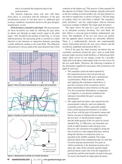
Figure 2—Pitch (or index) measurements on a gear with eccentricity.<br />
centered on the datum axis. This process is then repeated for<br />
the opposite set of flanks. These readings, typically referenced<br />
to the first reading on tooth number one, are then plotted in a<br />
bar chart or stepped line, as shown in Figure 2. The full range<br />
of reading values for each flank is labeled “the cumulative<br />
pitch deviation,” and the single-largest in terval between<br />
successive readings is labeled “the single-pitch deviation.”<br />
The figure shows the plot for a gear with eccentricity<br />
as its dominant accuracy deviation. For each flank, the<br />
plot follows a once-per-gear-revolution mathe matical sine<br />
curve. The amplitudes of the two sine curves are similar,<br />
but the apparent phase locations are noticeably different.<br />
There is a mathematically derived, and experimentally<br />
tested, relationship be tween the sine curve features and the<br />
eccentricity amplitude and direction (Ref. 6).<br />
Even if the gear has other accuracy deviations that are<br />
essentially consistent around the gear—such as tooth flank<br />
pressure angle, incorrect tooth thickness, or helical gear helix<br />
angle—these curves do not change except for a possible,<br />
slight shift in the phase relationship of the two sine curves for<br />
the two tooth flanks. Therefore, the following evaluation of<br />
the information supplied for most gears with eccentricity will<br />
apply in each case:<br />
• The cumulative pitch deviation reported by<br />
this inspection process does not provide any<br />
direct information about the gear’s manufacture<br />
or performance. What it does do, indirectly,<br />
after applying the calculation noted above, is<br />
provide a measure of the eccentricity and its<br />
phase relationship to some reference on the gear.<br />
Yet, this eccentricity information, as important<br />
as it might be, is not directly included in the<br />
tolerances that define the gear’s accuracy<br />
classification.<br />
• The single-pitch deviation value reported by this<br />
measurement is directly, and even indirectly,<br />
essentially useless. What is generally needed<br />
from a tooth spacing measurement is an indication<br />
of how well the gear will transfer contact and<br />
load as one pair of mating teeth are replaced by<br />
the next pair. A smooth transfer requires<br />
that the tooth spacing of the two gears be closely<br />
match ed (Fig. 3). Otherwise, any mismatch can<br />
result in added dynamic loads and gear noise.<br />
However, this mismatch to be judged is along the<br />
line of action in a base tan gent direction, and not<br />
along the tolerance or inspection circle, as<br />
specified in the AGMA standard. The singlepitch<br />
deviation in the standard provides no such lineof-action<br />
spacing measurement. For gears in<br />
which eccentricity is the dominant accuracy deviation,<br />
the value of the currently reported singlepitch<br />
deviation comes only from the magnitude of<br />
ec centricity and the total number of teeth in the gear.<br />
To receive the benefit of single-pitch deviation


