Magnetic anisotropy and metal-insulator transition in SrRuO3 thin ...
Magnetic anisotropy and metal-insulator transition in SrRuO3 thin ...
Magnetic anisotropy and metal-insulator transition in SrRuO3 thin ...

You also want an ePaper? Increase the reach of your titles
YUMPU automatically turns print PDFs into web optimized ePapers that Google loves.
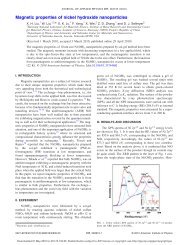
113925-2 Wang et al. J. Appl. Phys. 107, 113925 2010<br />
gradually weaker result<strong>in</strong>g f<strong>in</strong>ally <strong>in</strong> magnetic isotropy be<strong>in</strong>g<br />
found <strong>in</strong> films grown at 600 °C. In addition, we have conducted<br />
a detailed research on the effect of different stra<strong>in</strong> on<br />
the <strong>metal</strong>-<strong><strong>in</strong>sulator</strong> <strong>transition</strong> <strong>in</strong> SRO th<strong>in</strong> film at different<br />
growth temperatures.<br />
II. EXPERIMENTAL DETAILS<br />
The SRO films with a thickness of 200 nm were grown<br />
on 001 SrTiO 3 substrates by pulsed laser deposition PLD<br />
us<strong>in</strong>g a KrF =248 nm excimer laser, with a flux of approximately<br />
2 J/cm 2 <strong>and</strong> a repetition rate of 2 Hz under a<br />
process pressure of 0.3 mbar of pure O 2 at substrate temperatures<br />
rang<strong>in</strong>g between 600 <strong>and</strong> 750 °C. The films were then<br />
cooled to room temperature at 2 °C per m<strong>in</strong>ute under an<br />
oxygen pressure of 0.4 bar after deposition. Prior to deposition,<br />
the PLD chamber was completely cleaned <strong>and</strong> the other<br />
target <strong>in</strong> the chamber was completely enclosed leav<strong>in</strong>g only<br />
the SRO target was exposed, thus prevent<strong>in</strong>g any crosscontam<strong>in</strong>ation<br />
of the film from the other target. The substrate<br />
was cleaned <strong>in</strong> an ultrasonic bath with acetone followed by<br />
ethanol, with no other pretreatment be<strong>in</strong>g done. The chamber<br />
was then evacuated us<strong>in</strong>g a turbopump down to about 2<br />
10 −7 mbar to remove any extraneous particles. The structural<br />
quality <strong>and</strong> lattice parameters of the th<strong>in</strong> films were<br />
<strong>in</strong>vestigated us<strong>in</strong>g an x-ray diffractometer XRD, D/max-<br />
2000 Cu K =1.5406 Å <strong>and</strong> transmission electron microscope<br />
TEM. Bulk SRO crystallizes <strong>in</strong> an orthorhombic<br />
Pnma structure with lattice parameters a=5.5670 Å, b<br />
=5.5304 Å, <strong>and</strong> c=7.8446 Å. Its lattice parameter is 3.930<br />
Å <strong>in</strong> pseudocubic notation. The planes <strong>and</strong> directions of SRO<br />
referred to <strong>in</strong> this paper are based on the orthorhombic unit<br />
cell. Surface morphology was <strong>in</strong>vestigated us<strong>in</strong>g atomic<br />
force microscopy AFM, Digital Instruments, Nanoscope IV<br />
<strong>in</strong> tapp<strong>in</strong>g mode. <strong>Magnetic</strong> properties were measured by a<br />
superconduct<strong>in</strong>g quantum <strong>in</strong>terference device magnetometer<br />
with magnetic fields up to 70 kOe. Transport properties were<br />
measured <strong>in</strong> the <strong>in</strong>-plane IP direction by the st<strong>and</strong>ard fourterm<strong>in</strong>al<br />
method <strong>in</strong> the range from 5 to 310 K.<br />
III. RESULTS AND DISCUSSION<br />
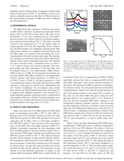
Figure 1a shows the -2 XRD patterns for SRO films<br />
grown at temperatures from 600 to 750 °C. Only SRO reflections<br />
close to the STO 001-family are found, but when<br />
SRO films are grown on 001 STO, the film can be grown<br />
epitaxially with its 001, 110, or11¯0 planes parallel to<br />
the STO 001 surface. 10 Also, because of the near degeneracy<br />
of the 002 <strong>and</strong> 110 planar spac<strong>in</strong>g of SRO, it is<br />
difficult to absolutely determ<strong>in</strong>e the film orientations with<br />
the -2 XRD patterns as the only reference. Figure 1b is a<br />
cross-sectional TEM image show<strong>in</strong>g the morphology of the<br />
SRO film grown on STO at 700 °C. The <strong>in</strong>terface between<br />
the film <strong>and</strong> the substrate is sharp <strong>and</strong> flat. Electron diffraction<br />
experiments clarify that the as-grown SRO film is composed<br />
of doma<strong>in</strong>s of both 001-oriented <strong>and</strong> 11¯0-oriented,<br />
as shown <strong>in</strong> Figs. 1c <strong>and</strong> 1d, taken from the areas <strong>in</strong>clud<strong>in</strong>g<br />
both the film <strong>and</strong> the substrate. The dimension of each<br />
doma<strong>in</strong> is several hundreds nanometers <strong>in</strong> length, so that<br />
electron diffraction pattern EDP from a s<strong>in</strong>gle doma<strong>in</strong> can<br />
FIG. 1. Color onl<strong>in</strong>e a The -2 XRD patterns for SRO films grown at<br />
substrate temperature rang<strong>in</strong>g from 600 to 750 °C. b The low magnification<br />
TEM micrograph for a cross-sectional film grown at 700 °C. c <strong>and</strong><br />
d Electron diffraction patters of two different regions of SRO film grown<br />
on at 700 °C. e The growth temperature T g dependence of OOP lattice<br />
constants c.<br />
be obta<strong>in</strong>ed. Figure 1c is a superposition of EDPs of 001 f<br />
<strong>and</strong> 100 s , whereas Fig. 1d is a composite EDP of 11¯0 f<br />
<strong>and</strong> 100 s . Subscripts s <strong>and</strong> f denote substrate <strong>and</strong> film, respectively.<br />
The <strong>in</strong>dexation of SRO is based on an orthorhombic<br />
structure. In Fig. 1c, the growth direction of the 001oriented<br />
doma<strong>in</strong> is along 110; while the growth direction of<br />
the 11¯0-oriented doma<strong>in</strong> is also along 110, as shown <strong>in</strong><br />
Fig. 1d. So, the whole SRO film grows along the 110<br />
direction which is very similar to Ref. 11. It is observed <strong>in</strong><br />
Fig. 1e that the calculated OOP lattice constant c <strong>in</strong><br />
pseudocubic notation gradually <strong>in</strong>creases with decreas<strong>in</strong>g<br />
growth temperature. Moreover, a shoulder is observed <strong>in</strong> the<br />
right side of the SRO peak <strong>in</strong> films grown at 650 <strong>and</strong> 700 °C<br />
shown <strong>in</strong> Fig. 1, <strong>in</strong>dicat<strong>in</strong>g an <strong>in</strong>termediate evolution of the<br />
OOP lattice constant that is between 0.403 nm found <strong>in</strong> the<br />
film grown at 600 °C <strong>and</strong> 0.395 nm for the one grown at<br />
750 °C, <strong>and</strong> corresponds to a state of partial stra<strong>in</strong> relaxation.<br />
Figure 2 shows the three-dimensional 3D AFM surface<br />
morphologies of SRO films grown at different temperatures<br />
<strong>and</strong> also of the raw STO substrate. The surface of the raw<br />
STO substrate as reference is very smooth with a roughness<br />
of 0.2 nm 55 m 2 . Irregular 3D isl<strong>and</strong>s are observed <strong>in</strong><br />
the surface of the film grown at 600 °C with these isl<strong>and</strong>s<br />
becom<strong>in</strong>g larger <strong>and</strong> of a more uniform size as the growth<br />
temperature is <strong>in</strong>creased to 650 °C. The isl<strong>and</strong>s then fade as<br />
the temperature reaches 700 °C <strong>and</strong> almost disappear at a<br />
growth temperature of 750 °C. The root-mean-square roughness<br />
of the film surface 55 m 2 is 3.34 nm <strong>and</strong> 3.76 nm<br />
for films grown at 600 °C <strong>and</strong> 650 °C, respectively, <strong>and</strong><br />
becomes 1.12 <strong>and</strong> 0.98 nm for films grown at 700 <strong>and</strong><br />
Downloaded 09 Jul 2010 to 210.72.130.85. Redistribution subject to AIP license or copyright; see http://jap.aip.org/jap/copyright.jsp