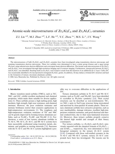
Atomic-scale microstructures of Zr2Al3C4 and Zr3Al3C5 ceramics
Atomic-scale microstructures of Zr2Al3C4 and Zr3Al3C5 ceramics
Atomic-scale microstructures of Zr2Al3C4 and Zr3Al3C5 ceramics

You also want an ePaper? Increase the reach of your titles
YUMPU automatically turns print PDFs into web optimized ePapers that Google loves.
Acta Materialia 54 (2006) 3843–3851<br />
www.actamat-journals.com<br />
<strong>Atomic</strong>-<strong>scale</strong> <strong>microstructures</strong> <strong>of</strong> Zr 2 Al 3 C 4 <strong>and</strong> Zr 3 Al 3 C 5 <strong>ceramics</strong><br />
Z.J. Lin a,b , M.J. Zhuo a,b , L.F. He a,b , Y.C. Zhou a, *, M.S. Li a , J.Y. Wang a<br />
a Shenyang National Laboratory for Materials Science, Institute <strong>of</strong> Metal Research, Chinese Academy <strong>of</strong> Sciences,<br />
72 Wenhua Road, Shenyang, Liaoning 110016, China<br />
b Graduate School <strong>of</strong> Chinese Academy <strong>of</strong> Sciences, Beijing 100039, China<br />
Received 11 December 2005; received in revised form 19 February 2006; accepted 24 February 2006<br />
Available online 27 June 2006<br />
Abstract<br />
The <strong>microstructures</strong> <strong>of</strong> bulk Zr 2 Al 3 C 4 <strong>and</strong> Zr 3 Al 3 C 5 <strong>ceramics</strong> have been investigated using transmission electron microscopy <strong>and</strong><br />
scanning transmission electron microscopy. These two carbides were determined to have a point group 6/mmm <strong>and</strong> a space group<br />
P6 3 /mmc using selected-area electron diffraction <strong>and</strong> convergent beam electron diffraction. The atomic-<strong>scale</strong> <strong>microstructures</strong> <strong>of</strong> Zr 2 Al 3 C 4<br />
<strong>and</strong> Zr 3 Al 3 C 5 were investigated through high-resolution imaging <strong>and</strong> Z-contrast imaging. Furthermore, intergrowth between Zr 2 Al 3 C 4<br />
<strong>and</strong> Zr 3 Al 3 C 5 was identified. Stacking faults in Zr 3 Al 3 C 5 were found to result from the insertion <strong>of</strong> an additional Zr–C layer. Cubic ZrC<br />
was occasionally identified to be incorporated in elongated Zr 3 Al 3 C 5 grains. In addition, Al may induce a twinned ZrC structure <strong>and</strong> lead<br />
to the formation <strong>of</strong> ternary zirconium aluminum carbides.<br />
Ó 2006 Acta Materialia Inc. Published by Elsevier Ltd. All rights reserved.<br />
Keywords: TEM; Carbides; Layered structures; STEM<br />
1. Introduction<br />
* Corresponding author. Tel.: +86 24 23971765; fax: +86 24 23891320.<br />
E-mail address: yczhou@imr.ac.cn (Y.C. Zhou).<br />
Binary transition metal carbides (TMCs), such as TiC,<br />
NbC, <strong>and</strong> ZrC, exhibit excellent mechanical <strong>and</strong> chemical<br />
properties, which make them suitable for diverse applications<br />
[1]. These carbides possess a high melting point, high<br />
hardness, high strength, high wear resistance, <strong>and</strong> chemical<br />
inertness. However, the poor oxidation resistance <strong>and</strong><br />
intrinsic brittleness restrict their extensive applications in<br />
high-temperature environments [1]. The toughness <strong>and</strong><br />
high-temperature oxidation resistance <strong>of</strong> TiC <strong>and</strong> NbC<br />
can be greatly improved by forming ternary aluminum carbides,<br />
such as Ti 3 AlC 2 ,Ti 2 AlC, <strong>and</strong> Nb 2 AlC [2–6]. Furthermore,<br />
a series <strong>of</strong> new ternary aluminum carbides in<br />
Ti–Al–C, Nb–Al–C, Zr–Al–C, <strong>and</strong> Hf–Al–C systems have<br />
been successfully synthesized using transition metals, aluminum,<br />
<strong>and</strong> graphite as starting materials [7,8]. Successes<br />
with the Ti–Al–C <strong>and</strong> Nb–Al–C systems highlighted a possible<br />
way to overcome difficulties in the applications <strong>of</strong><br />
ZrC.<br />
Ternary aluminum carbides in Ti–Al–C <strong>and</strong> Nb–Al–C<br />
systems, such as Ti 3 AlC 2 <strong>and</strong> Nb 2 AlC, have been identified<br />
to crystallize in P6 3 /mmc symmetry [2,8]. Their crystal<br />
structures can be described as non-stoichiometric TiC x<br />
(or NbC x ) units in NaCl-type structure being intercalated<br />
<strong>and</strong> mirrored by close-packed Al atomic planes. These ternary<br />
aluminum carbides have attractive properties, such as<br />
easy machinability, damage tolerance, excellent high-temperature<br />
oxidation resistance, <strong>and</strong> good electrical <strong>and</strong> thermal<br />
conductivities, due to their nano-laminated structures<br />
[6]. Moreover, these ternary carbides properly conserve<br />
the desired high moduli <strong>and</strong> strength <strong>of</strong> their binary<br />
counterparts.<br />
Two ternary carbides, i.e. Zr 2 Al 3 C 4 <strong>and</strong> Zr 3 Al 3 C 5 (previously<br />
reported with the chemical formula <strong>of</strong> Zr 2 Al 3 C 5 x<br />
<strong>and</strong> ZrAlC 2 x , respectively [8]), were determined to have<br />
hexagonal symmetry in the ternary Zr–Al–C system<br />
[9,10]. Compared with those well-studied <strong>ceramics</strong> in the<br />
Ti–Al–C <strong>and</strong> Nb–Al–C systems, ternary Zr–Al–C compounds<br />
have been less investigated. The reasons can be<br />
1359-6454/$30.00 Ó 2006 Acta Materialia Inc. Published by Elsevier Ltd. All rights reserved.<br />
doi:10.1016/j.actamat.2006.02.052
3844 Z.J. Lin et al. / Acta Materialia 54 (2006) 3843–3851<br />
attributed to difficulties in synthesizing bulk materials <strong>and</strong><br />
lack <strong>of</strong> knowledge <strong>of</strong> the microstructural characteristics<br />
<strong>and</strong> mechanical <strong>and</strong> chemical properties.<br />
Hashimoto et al. [11] fabricated Zr 3 Al 3 C 5 -based composites<br />
<strong>and</strong> reported that the composites displayed satisfactory<br />
oxidation resistance. Recently, Leela-adisorn et al.<br />
[12,13] fabricated bulk Zr 2 Al 3 C 4 <strong>and</strong> Zr 3 Al 3 C 5 from the<br />
corresponding compound powders which were prepared<br />
by solid-state reaction <strong>of</strong> ZrC, Al, <strong>and</strong> graphite. The fracture<br />
strength <strong>and</strong> Vickers hardness were tentatively characterized<br />
for Zr 3 Al 3 C 5 . He et al. [14] synthesized Zr 3 Al 3 C 5<br />
powders using Zr–Al intermetallics <strong>and</strong> graphite as starting<br />
materials. Oxidation tests indicated that Zr 3 Al 3 C 5 powders<br />
displayed higher oxidation resistance than ZrC [14].<br />
Despite these achievements, the structural information<br />
for Zr 2 Al 3 C 4 <strong>and</strong> Zr 3 Al 3 C 5 is very limited <strong>and</strong> confused.<br />
Using X-ray diffraction analysis, the space group <strong>of</strong><br />
Zr 2 Al 3 C 4 was reported to be P31 c (C 4 3vÞ by Schuster <strong>and</strong><br />
Nowotny [8], P6 3 /mmc by Parthé <strong>and</strong> Chabot [10], <strong>and</strong><br />
P6 3 mc by Fukuda et al. [15]. Similarly, Zr 3 Al 3 C 5 has been<br />
reported to have P6 3 /mmc [8,9] <strong>and</strong> P6 3 mc symmetry [16].<br />
Therefore, it is necessary to clarify the symmetry <strong>of</strong> both<br />
carbides. Furthermore, atomic-<strong>scale</strong> <strong>microstructures</strong> are<br />
valuable in underst<strong>and</strong>ing the structures <strong>and</strong> properties<br />
<strong>of</strong> these two ternary carbides.<br />
In this work, the microstructural characterizations <strong>of</strong><br />
two ternary Zr–Al–C <strong>ceramics</strong> were carried out by means<br />
<strong>of</strong> transmission electron microscopy (TEM) <strong>and</strong> scanning<br />
transmission electron microscopy (STEM). The symmetry<br />
<strong>of</strong> both carbides was determined using selected-area electron<br />
diffraction (SAED) <strong>and</strong> convergent beam electron diffraction<br />
(CBED). <strong>Atomic</strong>-<strong>scale</strong> <strong>microstructures</strong> <strong>of</strong> both<br />
carbides were characterized <strong>and</strong> are discussed in this paper.<br />
which was equipped with a high-angle annular dark-field<br />
(HAADF) detector in the STEM system <strong>and</strong> a postcolumn<br />
Gatan imaging filter system, was used for highresolution<br />
imaging <strong>and</strong> Z-contrast STEM imaging. Fast<br />
Fourier transformation (FFT) was carried out using a<br />
DigitalMicrograph s<strong>of</strong>tware package.<br />
3. Results <strong>and</strong> discussion<br />
3.1. Symmetry determination <strong>of</strong> Zr 2 Al 3 C 4 <strong>and</strong> Zr 3 Al 3 C 5<br />
Fig. 1(a) <strong>and</strong> (b) show the crystal structures <strong>of</strong> Zr 2 Al 3 C 4<br />
<strong>and</strong> Zr 3 Al 3 C 5 , respectively [8,10]. The atomic arrangements<br />
<strong>of</strong> these two carbides are further illustrated in Fig. 1(c) <strong>and</strong><br />
(d) using two 2 · 2 · 1 slices on the ð1 210Þ plane. As<br />
described by Gesing <strong>and</strong> Jeitschko [16] <strong>and</strong> by Fukuda<br />
et al. [15], Zr 2 Al 3 C 4 <strong>and</strong> Zr 3 Al 3 C 5 can be viewed as inter-<br />
2. Experimental<br />
Bulk Zr 2 Al 3 C 4 <strong>and</strong> Zr 3 Al 3 C 5 <strong>ceramics</strong> were prepared<br />
through a hot pressing method using elemental powders<br />
<strong>of</strong> zirconium (99% purity, 400 mesh), aluminum (99%<br />
purity, 200 mesh), <strong>and</strong> graphite (99% purity, 200 mesh)<br />
as starting materials. Powder mixtures <strong>of</strong> appropriate stoichiometry<br />
were homogenized using ethanol as a mixing<br />
medium in a planetary ball mill for 12 h <strong>and</strong> then dried<br />
at room temperature for 24 h. Afterwards, the mixed powders<br />
were uniaxially pressed under a pressure <strong>of</strong> 10 MPa in<br />
a BN-coated graphite mold <strong>of</strong> 25 mm in diameter. The<br />
compacted mixture was heated to 1700 °C at a heating rate<br />
<strong>of</strong> 15 °C/min <strong>and</strong> then hot pressed for 1 h in a flowing Ar<br />
atmosphere. The applied pressure was 35 MPa during the<br />
synthesis <strong>of</strong> both carbides. The surface layers <strong>of</strong> the samples<br />
were machined <strong>of</strong>f using a SiC grinding wheel to<br />
remove contaminants arising from the graphite mold.<br />
Thin-foil specimens for TEM observations were prepared<br />
by slicing, mechanical grinding to 20 lm, dimpling<br />
down to 10 lm, <strong>and</strong> ion milling at 4.0 kV. A 200 kV<br />
JEM-2010 TEM instrument was used for SAED <strong>and</strong><br />
CBED analysis. A 300 kV Tecnai G 2 F30 TEM instrument,<br />
Fig. 1. Crystal structures <strong>of</strong>: (a) Zr 2 Al 3 C 4 <strong>and</strong> (b) Zr 3 Al 3 C 5 . <strong>Atomic</strong><br />
arrangements <strong>of</strong> two 2 · 2 · 1 slices on the ð1 210Þ plane <strong>of</strong> (c) Zr 2 Al 3 C 4<br />
<strong>and</strong> (d) Zr 3 Al 3 C 5 . The main difference between these two carbides centers<br />
on the (ZrC) m units.
Z.J. Lin et al. / Acta Materialia 54 (2006) 3843–3851 3845<br />
growth structures consisting <strong>of</strong> two kinds <strong>of</strong> layers. One is<br />
the non-stoichiometric (ZrC) m (m = 2 or 3) slab in the<br />
NaCl-type structure <strong>and</strong> the other consists <strong>of</strong> Al 3 C 2 units<br />
in an arrangement similar to that <strong>of</strong> the binary aluminum<br />
carbide Al 4 C 3 . The structural difference is that m = 2 for<br />
Zr 2 Al 3 C 4 , while m = 3 for Zr 3 Al 3 C 5 .<br />
The combination <strong>of</strong> SAED <strong>and</strong> CBED has been successfully<br />
used in determining the symmetry <strong>of</strong> ternary carbides<br />
such as Ti 3 SiC 2 [17] <strong>and</strong> Ti 3 AlC 2 [18]. Therefore, these two<br />
methods were used to identify the symmetry <strong>of</strong> ternary Zr–<br />
Al–C carbides in this work. Fig. 2(a)–(c) show SAED patterns<br />
which were indexed as [0001], ½1 210Š, <strong>and</strong> ½1 100Š<br />
zone axes, respectively, <strong>of</strong> the hexagonal Zr 2 Al 3 C 4 . From<br />
these patterns <strong>of</strong> low-indices basic zone axes, the lattice<br />
parameters were derived as a = 0.33 nm <strong>and</strong> c = 2.24 nm,<br />
which were consistent with those determined from powder<br />
X-ray analysis [8,14,15]. These SAED patterns were also<br />
informative for learning extinction rules. It is noted that<br />
all reflections in the ½1 210Š pattern appeared, but the<br />
(000l) (l = odd) reflections in the ½1 100Š pattern were<br />
absent, implying the existence <strong>of</strong> a c glide plane. The<br />
appearance <strong>of</strong> the {0 00l} (l = odd) reflections in the<br />
½1 210Š pattern can be attributed to double diffraction<br />
[18–20]. Fig. 2(d) shows an SAED pattern whose orientation<br />
was positioned between ½1 210Š <strong>and</strong> ½1 100Š. As shown<br />
in Fig. 2(d), the (000l) reflections with l = odd were also<br />
absent which indicated that there was a 6 3 screw axis along<br />
the [0001] axis [18,19]. Fig. 2(e) shows a CBED pattern<br />
obtained from a Zr 2 Al 3 C 4 grain along the [0001] zone axis.<br />
A sixfold axis <strong>of</strong> rotational symmetry as well as two independent<br />
<strong>and</strong> mutually perpendicular mirror planes (each <strong>of</strong><br />
which is reproduced every 60° by the action <strong>of</strong> the sixfold<br />
axis) were observed. These two types <strong>of</strong> mirror planes are<br />
parallel to the sixfold axis. The symmetry was determined<br />
to be 6mm. In addition, the symmetry shown in the SAED<br />
½1 210Š pattern (Fig. 2(b)) was 2mm. A6mm symmetry <strong>and</strong><br />
a2mm symmetry indicate a unique 6/mmm point group for<br />
Zr 2 Al 3 C 4 [17–19]. Fig. 2(f) shows a CBED pattern showing<br />
the existence <strong>of</strong> a mirror plane on (0001). A 6mm symmetry<br />
<strong>and</strong> a mirror plane on (0001) further confirm the<br />
6/mmm point group for Zr 2 Al 3 C 4 . A combination <strong>of</strong> the<br />
information derived from these SAED <strong>and</strong> CBED patterns<br />
indicate that Zr 2 Al 3 C 4 has a space group P6 3 /mmc, which<br />
agrees well with the results <strong>of</strong> Parthé <strong>and</strong> Chabot [10].<br />
Fig. 2. (a–c) SAED patterns <strong>of</strong> hexagonal Zr 2 Al 3 C 4 with the electron beam parallel to the directions <strong>of</strong> [0001], ½1 210Š, <strong>and</strong> ½1 100Š, respectively. (d) An<br />
SAED pattern with the orientation being positioned between ½1 210Š <strong>and</strong> ½1 100Š. (e) A CBED pattern showing the symmetry <strong>of</strong> a sixfold rotation about<br />
the [0001] axis <strong>and</strong> also the symmetry <strong>of</strong> the mirror reflection across two independent planes. (f) A CBED pattern showing the existence <strong>of</strong> a mirror plane<br />
on (0001).
3846 Z.J. Lin et al. / Acta Materialia 54 (2006) 3843–3851<br />
The symmetry <strong>of</strong> Zr 3 Al 3 C 5 was also determined using<br />
SAED <strong>and</strong> CBED. The lattice parameters obtained were<br />
a = 0.33 nm <strong>and</strong> c = 2.76 nm, which are in good agreement<br />
with previously reported data [9,16]. Zr 3 Al 3 C 5 was also<br />
determined to have a point group 6/mmm <strong>and</strong> a space<br />
group P6 3 /mmc, which is consistent with that reported by<br />
Mikhalenko et al. [8,9]. The SAED <strong>and</strong> CBED patterns<br />
<strong>of</strong> Zr 3 Al 3 C 5 were similar to those <strong>of</strong> Zr 2 Al 3 C 4 <strong>and</strong> are<br />
therefore not shown for brevity.<br />
3.2. Microstructure <strong>of</strong> hexagonal Zr 2 Al 3 C 4 <strong>and</strong> Zr 3 Al 3 C 5<br />
Fig. 3(a) <strong>and</strong> (b) display the low-magnification brightfield<br />
TEM images <strong>of</strong> Zr 2 Al 3 C 4 <strong>and</strong> Zr 3 Al 3 C 5 , respectively.<br />
The overall characteristics <strong>of</strong> the <strong>microstructures</strong> <strong>of</strong> the assynthesized<br />
<strong>ceramics</strong> can be observed. Extensive TEM<br />
observations have shown that the Zr 2 Al 3 C 4 grains had salient<br />
features, i.e. the grains generally had elongated morphologies<br />
ranging from 2 to 20 lm in length <strong>and</strong> 30 to<br />
500 nm in width in the perpendicular direction. SAED<br />
analysis revealed that the crystallographic direction<br />
[0001] <strong>of</strong> Zr 2 Al 3 C 4 was perpendicular to the elongated<br />
direction <strong>of</strong> the Zr 2 Al 3 C 4 grains. Rotations between grains<br />
were found to be along the [0001] axis <strong>and</strong> along the direction<br />
perpendicular to [0001]. Most <strong>of</strong> the grain boundaries<br />
were large-angle grain boundaries; <strong>and</strong> grains with misorientation<br />
<strong>of</strong> only several degrees were also observed. In contrast,<br />
the Zr 3 Al 3 C 5 grains were less regular as displayed in<br />
Fig. 3(b). In addition, some grains were found to crystallize<br />
in the form <strong>of</strong> elongated slabs, which were similar to those<br />
in Zr 2 Al 3 C 4 .<br />
It is generally believed that elongated grains with large<br />
aspect ratio would benefit the toughness <strong>of</strong> <strong>ceramics</strong>. For<br />
example, elongated Si 3 N 4 grains were effective in toughening<br />
a ceramic by crack deflection <strong>and</strong> crack bridging<br />
[21,22].SoZr 2 Al 3 C 4 with elongated grains may display better<br />
toughness than Zr 3 Al 3 C 5 . The difference <strong>of</strong> grain morphologies<br />
between Zr 2 Al 3 C 4 <strong>and</strong> Zr 3 Al 3 C 5 may originate<br />
from the different liquid phase content during the synthesizing<br />
processes. It is possible that the relatively higher<br />
liquid phase during the synthesis <strong>of</strong> Zr 2 Al 3 C 4 favors the<br />
formation <strong>of</strong> elongated grains. During the synthesis <strong>of</strong><br />
Si 3 N 4 , Perera et al. [22] have shown that sintering additives<br />
strongly influence the grain morphologies <strong>of</strong> the <strong>ceramics</strong><br />
by controlling the liquid phase content. Their work may<br />
support our hypothesis.<br />
Fig. 4 shows a high-resolution TEM (HRTEM) image<br />
<strong>of</strong> Zr 2 Al 3 C 4 obtained with the incident beam parallel to<br />
the ½1 210Š direction. The image fringes with a periodicity<br />
<strong>of</strong> 2.24 nm along the [0001] direction can be clearly seen.<br />
The C atoms cannot be resolved in the microscopes<br />
because <strong>of</strong> its weak diffraction power. The bright spots<br />
can be described as a layered stacking with a sequence <strong>of</strong><br />
ABCBACBABC along the [0001] direction. This type <strong>of</strong><br />
stacking sequence corresponds to the Zr <strong>and</strong> Al atoms in<br />
the Zr 2 Al 3 C 4 structure <strong>and</strong> is consistent with the structure<br />
previously proposed by Parthé <strong>and</strong> Chabot [10].<br />
Unfortunately, the atomic positions <strong>of</strong> Zr <strong>and</strong> Al cannot<br />
be distinguished using conventional HRTEM because this<br />
technique uses phase-contrast imaging.<br />
Z-contrast STEM imaging, which was developed by<br />
Pennycook <strong>and</strong> co-workers [23,24], can efficiently<br />
distinguish different atoms because this technique uses<br />
high-angle inelastic electrons. This technique removes the<br />
coherent effects <strong>of</strong> diffraction <strong>and</strong> leads to strong atomic<br />
number, Z, contrast. The intensity <strong>of</strong> the obtained image<br />
is proportional to Z 2 , the square <strong>of</strong> atomic number.<br />
Therefore, Z-contrast STEM images are more directly<br />
Fig. 3. Typical TEM bright-field images <strong>of</strong>: (a) Zr 2 Al 3 C 4 <strong>and</strong> (b) Zr 3 Al 3 C 5 . The Zr 2 Al 3 C 4 grains generally have elongated morphologies while the<br />
Zr 3 Al 3 C 5 grains are irregular.
Z.J. Lin et al. / Acta Materialia 54 (2006) 3843–3851 3847<br />
Fig. 4. HRTEM image <strong>of</strong> Zr 2 Al 3 C 4 obtained with the incident beam<br />
parallel to the ½1 210Š direction.<br />
interpretable than conventional phase-contrast images <strong>and</strong><br />
this method was used to determine the positions <strong>of</strong> Al <strong>and</strong><br />
Zr in ternary Zr–Al–C carbides. Fig. 5(a) displays a raw<br />
high-resolution Z-contrast STEM image <strong>of</strong> Zr 2 Al 3 C 4<br />
viewed along the ½1 210Š direction. The main experimental<br />
parameters were a probe size <strong>of</strong> 0.17 nm <strong>and</strong> detector semiangles<br />
<strong>of</strong> 36–100 mrad. An inner detector semi-angle <strong>of</strong><br />
36 mrad was used for the following two reasons. Firstly,<br />
Pennycook <strong>and</strong> co-workers [25] proposed that the detector<br />
semi-angle depends on the electron wavelength <strong>and</strong> point<br />
resolution. A criterion <strong>of</strong> semi-angle to obtain incoherent<br />
images can be described by the following equation:<br />
b > 1:22k=DR<br />
ð1Þ<br />
where b is the semi-angle, k is the electron wavelength, <strong>and</strong><br />
DR is the point resolution <strong>of</strong> the TEM. In this work, a<br />
Tecnai G 2 F30 TEM instrument working at 300 kV was<br />
used for Z-contrast imaging. k <strong>and</strong> DR are 0.0197 <strong>and</strong><br />
1.7 Å, respectively. As a result, 1.22k/DR = 14.1 mrad.<br />
Consequently, incoherent images can be obtained with an<br />
inner angle larger than 14.1 mrad in the present system.<br />
Secondly, the atomic number <strong>of</strong> Zr (Z = 40) is relatively<br />
large; in order to reduce the coherent effect <strong>of</strong> Zr atomic<br />
columns, an inner detector semi-angle <strong>of</strong> 36 mrad was used.<br />
The atomic positions <strong>of</strong> Zr <strong>and</strong> Al were clearly characterized<br />
in the Z-contrast image since the intensity <strong>of</strong> a spot reflects<br />
the atomic number <strong>of</strong> the corresponding atom. As<br />
shown in Fig. 5(b), an important feature <strong>of</strong> Zr 3 Al 3 C 5 is that<br />
the three Zr layers separate the Al 3 C 2 units, as well as two<br />
Zr layers in Zr 2 Al 3 C 4 . This is consistent with the crystal<br />
structures shown in Fig. 1.<br />
Fig. 6(a) shows an intergrown structure between<br />
Zr 2 Al 3 C 4 <strong>and</strong> Zr 3 Al 3 C 5 . The corresponding FFT filtered<br />
image <strong>of</strong> Fig. 6(a) is displayed in Fig. 6(b) The intergrowth<br />
between these two carbides can be understood as follows.<br />
The lattice parameters a <strong>of</strong> Zr 2 Al 3 C 4 (0.3346 nm) [10]<br />
<strong>and</strong> Zr 3 Al 3 C 5 (0.3347 nm) [9] are essentially equal, which<br />
ensures an intergrowth with negligible lattice misfit; in<br />
addition, Zr 2 Al 3 C 4 shares a similar crystal structure with<br />
Zr 3 Al 3 C 5 with the only difference centering on the (ZrC) m<br />
units. Locally, enrichment <strong>of</strong> Zr in Zr 2 Al 3 C 4 may lead to<br />
the formation <strong>of</strong> Zr 3 Al 3 C 5 . Similar intergrown structures<br />
have been identified in the ternary Ti–Al–C [18,20] <strong>and</strong><br />
Ti–Si–C [26] systems.<br />
Fig. 5. High-resolution Z-contrast STEM images viewed along the ½1 210Š direction <strong>of</strong>: (a) Zr 2 Al 3 C 4 <strong>and</strong> (b) Zr 3 Al 3 C 5 .
3848 Z.J. Lin et al. / Acta Materialia 54 (2006) 3843–3851<br />
Fig. 6. Z-contrast STEM image <strong>of</strong> the intergrown structure <strong>of</strong> Zr 2 Al 3 C 4 <strong>and</strong> Zr 3 Al 3 C 5 : (a) raw image <strong>and</strong> (b) FFT filtered image. There can be either two<br />
or three Zr layers separating the Al 3 C 2 units.<br />
Besides the intergrown structure <strong>of</strong> Zr 2 Al 3 C 4 <strong>and</strong><br />
Zr 3 Al 3 C 5 , stacking faults were also identified in these two<br />
ternary carbides. Fig. 7(a) shows a low-magnification<br />
bright-field image <strong>of</strong> stacking faults in Zr 3 Al 3 C 5 . Bright<br />
<strong>and</strong> dark fringes were observed. In order to clarify the<br />
microstructure <strong>of</strong> the stacking faults, Z-contrast STEM<br />
images were obtained. As displayed in Fig. 7(b), the periodicity<br />
<strong>of</strong> the stacking sequence was not identical. The<br />
atomic-<strong>scale</strong> microstructure <strong>of</strong> the stacking faults is further<br />
illustrated in Fig. 7(c) <strong>and</strong> (d). The high-resolution Z-<br />
contrast image indicated that the stacking faults resulted<br />
from the insertion <strong>of</strong> an additional Zr–C layer. Yu et al.<br />
[27] also reported similar stacking faults with the insertion<br />
<strong>of</strong> additional Ti–C layers in the ternary Ti–Si–C system.<br />
The above observations demonstrate that the structural<br />
difference between Zr 2 Al 3 C 4 <strong>and</strong> Zr 3 Al 3 C 5 is the thickness<br />
<strong>of</strong> (ZrC) m units between the Al 3 C 2 units. In order to illustrate<br />
the influence <strong>of</strong> this difference on the properties <strong>of</strong> ternary<br />
Zr–Al–C carbides, theoretical mechanical properties<br />
for Zr 2 Al 3 C 4 <strong>and</strong> Zr 3 Al 3 C 5 are compared. The calculated<br />
bulk modulus B, shear modulus G, <strong>and</strong> anisotropic<br />
Young’s modulus E <strong>of</strong> ZrC, Zr 2 Al 3 C 4 , <strong>and</strong> Zr 3 Al 3 C 5 [28],<br />
together with experimental values for polycrystalline ZrC<br />
[29] are presented in Table 1. It is seen that the calculated<br />
data for ZrC agree well with the experimental values, suggesting<br />
the reliability <strong>of</strong> the theoretical results. The main<br />
difference in mechanical properties <strong>of</strong> Zr 2 Al 3 C 4 <strong>and</strong><br />
Zr 3 Al 3 C 5 lies in the magnitude <strong>of</strong> the shear modulus. The<br />
shear modulus <strong>of</strong> Zr 3 Al 3 C 5 (166 GPa) is 37% higher than<br />
that <strong>of</strong> Zr 2 Al 3 C 4 (121 GPa). Therefore, the shear modulus<br />
<strong>of</strong> ternary Zr–Al–C carbides strongly depends on the<br />
atomic-<strong>scale</strong> arrangements. It is also seen that Zr 3 Al 3 C 5<br />
properly conserves the excellent mechanical properties <strong>of</strong><br />
binary carbide ZrC. Consequently, Zr 3 Al 3 C 5 is predicted<br />
to be a promising carbide for ultrahigh-temperature applications.<br />
On the other h<strong>and</strong>, the low shear modulus may<br />
lead to Zr 2 Al 3 C 4 possessing similar properties to ternary<br />
carbides such as Ti 3 AlC 2 [3]. Therefore, it is very important<br />
to control the microstructure in the synthesized Zr–Al–C<br />
compounds.<br />
3.3. Determination <strong>of</strong> ZrC inclusions in Zr 3 Al 3 C 5 grains<br />
As shown in a Z-contrast image in Fig. 8(a), inclusions<br />
<strong>of</strong> rounded grains have been found. The contrasting white<br />
regions showed that the diameter <strong>of</strong> the circular grains ranged<br />
from 20 to 200 nm. Typical nanobeam diffraction<br />
(NBD) patterns taken from the inclusions are displayed<br />
in Fig. 8(b) <strong>and</strong> (c). These two NBD patterns were indexed<br />
to be [110] <strong>and</strong> [111] <strong>of</strong> cubic ZrC, which indicated that<br />
the inclusions were ZrC particles. Morgiel et al. [30] have<br />
also reported the inclusions <strong>of</strong> binary carbide TiC in the<br />
ternary Ti 3 SiC 2 ceramic.<br />
The present results for the microstructure are definitely<br />
useful in optimizing the processing <strong>and</strong> properties <strong>of</strong> these<br />
ternary carbides. Both carbides can be fabricated from elemental<br />
Zr, Al, <strong>and</strong> graphite powders at 1700 °C. Although<br />
X-ray diffraction analysis showed that the Zr 3 Al 3 C 5<br />
obtained is predominantly single phase, TEM analysis indicated<br />
that minor amounts <strong>of</strong> ZrC inclusions were present in<br />
the Zr 3 Al 3 C 5 grains (Fig. 8(a)–(c)). It has been demonstrated<br />
that Zr 3 Al 3 C 5 has higher oxidation resistance than<br />
ZrC [14]. To achieve good high-temperature oxidation<br />
resistance, further optimization is needed to improve the<br />
purity <strong>of</strong> Zr 3 Al 3 C 5 .<br />
High-resolution imaging <strong>of</strong> the inclusions was conducted.<br />
A typical FFT pattern <strong>of</strong> an HRTEM image <strong>of</strong><br />
ZrC is shown in Fig. 9(a). The FFT pattern was indexed<br />
to be twinned ZrC with the incident beam parallel to the<br />
[110] direction. Linear diffraction streaks besides the<br />
twinned reflections were observed, suggesting the presence<br />
<strong>of</strong> two-dimensional defects. Insight into the twinned ZrC
Z.J. Lin et al. / Acta Materialia 54 (2006) 3843–3851 3849<br />
Fig. 7. (a) Low-magnification bright-field image <strong>of</strong> stacking faults <strong>of</strong> Zr 3 Al 3 C 5 . (b) Medium-magnification Z-contrast image showing the periodicity <strong>of</strong> the<br />
stacking faults. (c) Raw high-magnification Z-contrast STEM image <strong>of</strong> a stacking fault resulting from the insertion <strong>of</strong> an additional ZrC layer. (d) FFT<br />
filtered image <strong>of</strong> (c). The arrows in (b) indicate the stacking faults.<br />
Table 1<br />
Calculated bulk modulus B, shear modulus G, <strong>and</strong> anisotropic Young’s<br />
modulus E <strong>of</strong> ZrC, Zr 2 Al 3 C 4 , <strong>and</strong> Zr 3 Al 3 C 5 , together with experimental<br />
values for polycrystalline ZrC for comparison<br />
Method B (GPa) G (GPa) E (GPa)<br />
ZrC Calc. [28] 229 170 408<br />
Expt. [29] 223 170 407<br />
Zr 2 Al 3 C 4 Calc. [28] 190 121 E x = 356<br />
E y = 302<br />
Zr 3 Al 3 C 5 Calc. [28] 202 166 E x = 388<br />
E y = 346<br />
microstructure showed that a very thin Al platelet with several<br />
atomic layers was present at the ZrC twin boundaries.<br />
A typical Z-contrast image with three Al atomic layers at a<br />
ZrC twin boundary is displayed in Fig. 9(b) <strong>and</strong> (c). The<br />
spots with higher intensity correspond to Zr <strong>and</strong> the rest<br />
denote Al. The structure <strong>of</strong> this thin Al platelet was identical<br />
to the Al 3 C 2 unit in ternary Zr–Al–C carbides, suggesting<br />
that ternary Zr–Al–C thin platelets could form at the<br />
ZrC twin boundaries.<br />
TEM investigations <strong>of</strong> bulk ZrC are very limited<br />
because <strong>of</strong> the difficulties in sintering ZrC ceramic [31].
3850 Z.J. Lin et al. / Acta Materialia 54 (2006) 3843–3851<br />
Fig. 8. (a) Z-contrast image <strong>of</strong> ZrC inclusions in an elongated Zr 3 Al 3 C 5 grain. (b, c) NBD patterns <strong>of</strong> cubic ZrC with the electron beam parallel to [110]<br />
<strong>and</strong> [111] directions.<br />
Fig. 9. (a) FFT image from a region containing ZrC twins. (b) Initial high-resolution Z-contrast STEM image <strong>of</strong> a twinned ZrC with three Al layers at the<br />
twin boundaries. (c) FFT filtered image <strong>of</strong> (b).<br />
The microstructural characteristics <strong>of</strong> TiC, another binary<br />
TMC with NaCl-type structure, have been extensively<br />
investigated [32,33]. Previous investigations showed that<br />
TiC has a high stacking fault energy. Interestingly, impurities<br />
such as Al <strong>and</strong> Si could stabilize the twinned TiC structure<br />
<strong>and</strong> induced the formation <strong>of</strong> ternary Ti–Si(Al)–C<br />
carbides [34,35]. Since ZrC <strong>and</strong> TiC have the same rocksalt<br />
structure, it is reasonable that Al can also efficiently<br />
reduce the twin boundary energy <strong>of</strong> ZrC <strong>and</strong> consequently<br />
lead to the formation <strong>of</strong> ternary Zr–Al–C carbides. It is<br />
also clear that ZrC serves as the intermediate phase during<br />
the synthesis <strong>of</strong> ternary Zr–Al–C carbides from Zr, Al, <strong>and</strong><br />
graphite elemental powders. This result leads to the interpretation<br />
that ternary Zr–Al–C carbides can be synthesized<br />
using elemental Zr, Al, <strong>and</strong> graphite powders as in this<br />
work, or ZrC <strong>and</strong> Al as in previous works [11–13].<br />
4. Conclusions<br />
The microstructural characteristics were investigated<br />
for Zr 2 Al 3 C 4 <strong>and</strong> Zr 3 Al 3 C 5 <strong>ceramics</strong>. The point group<br />
<strong>and</strong> space group <strong>of</strong> both carbides were determined to<br />
be 6/mmm <strong>and</strong> P6 3 /mmc, respectively, form SAED<br />
<strong>and</strong> CBED analyses. The lattice parameters <strong>of</strong> asprepared<br />
Zr 2 Al 3 C 4 (a = 0.33 nm <strong>and</strong> c = 2.24 nm) <strong>and</strong><br />
Zr 3 Al 3 C 5 (a = 0.33 nm <strong>and</strong> c = 2.76 nm) were<br />
obtained.<br />
The atomic-<strong>scale</strong> <strong>microstructures</strong> <strong>of</strong> these two carbides<br />
were determined through high-resolution imaging <strong>and</strong><br />
Z-contrast STEM imaging. Zr 3 Al 3 C 5 was identified to<br />
form an intergrown structure with Zr 3 Al 3 C 5 . Stacking<br />
faults in Zr 3 Al 3 C 5 resulted from the insertion <strong>of</strong> an additional<br />
Zr–C layer.
Z.J. Lin et al. / Acta Materialia 54 (2006) 3843–3851 3851<br />
Minor amounts <strong>of</strong> rounded ZrC inclusions were<br />
observed in the elongated Zr 3 Al 3 C 5 grains. Al was found<br />
to induce a twinned ZrC structure <strong>and</strong> lead to the formation<br />
<strong>of</strong> ternary Zr–Al–C carbides.<br />
Acknowledgements<br />
The authors thank Miss Y. Cui for revising this manuscript.<br />
This work was supported by the National Outst<strong>and</strong>ing<br />
Young Scientist Foundation for Y.C.Z. under Grant<br />
No. 59925208, Natural Sciences Foundation <strong>of</strong> China under<br />
Grant Nos. 50232040, 50302011, <strong>and</strong> 90403027.<br />
References<br />
[1] Nowotny H, Windisch S. Annu Rev Mater Sci 1973;3:171.<br />
[2] Pietzka MA, Schuster JC. J Phase Equilib 1994;15:392.<br />
[3] Wang XH, Zhou YC. Acta Mater 2002;50:3141.<br />
[4] Wang XH, Zhou YC. Oxid Met 2003;59:303.<br />
[5] Salama I, El-Raghy T, Barsoum MW. J Alloy Compd 2002;347:271.<br />
[6] Barsoum MW. Prog Solid State Chem 2000;28:201.<br />
[7] Schuster JC, Nowotny H, Vaccaro C. J Solid State Chem<br />
1980;32:213.<br />
[8] Schuster JC, Nowotny H. Z Metallkd 1980;71:341.<br />
[9] Mikhalenko SI, Kuz’ma YB, Popov VE, Gurin VN, Nechitailov AP.<br />
Izv Akad Nauk SSSR, Neorgan Mater 1979;15:1948.<br />
[10] Parthé E, Chabot B. Acta Crystallogr 1988;C44:774.<br />
[11] Hashimoto S, Yamaguchi A, Yasuda M. J Mater Sci 1998;33:4835.<br />
[12] Leela-adisorn U, Choi SM, Hashimoto S, Honda S, Awaji H. In:<br />
Proceedings <strong>of</strong> the 21st international Korea–Japan seminar on<br />
<strong>ceramics</strong>; 2004. p. 339.<br />
[13] Leela-adisorn U, Choi SM, Tera N, Takeuchi T, Hashimoto S,<br />
Honda S, Awaji H, Hayakawa K, Yamaguchi A. J Ceram Soc Jpn<br />
2005;113:188.<br />
[14] He LF, Zhou YC, Bao YW, Wang JY, Li MS [unpublished work].<br />
[15] Fukuda K, Mori S, Hashimoto S. J Am Ceram Soc 2005;88:3528.<br />
[16] Gesing TM, Jeitschko W. J Solid State Chem 1998;140:396.<br />
[17] Arunajatesan S, Carim AH. Mater Lett 1994;20:319.<br />
[18] Ma XL, Zhu YL, Wang XH, Zhou YC. Philos Mag 2004;84:2969.<br />
[19] Hahn T. International tables for crystallography, vol. A: space-group<br />
symmetry. Dordrecht: Kluwer; 1989.<br />
[20] Lin ZJ, Zhuo MJ, Zhou YC, Li MS, Wang JY. Acta Mater<br />
2006;54:1009.<br />
[21] Sun EY, Becher PF, Hsueh CH, Painter GS, Waters SB, Hwang SL,<br />
H<strong>of</strong>fmann MJ. Acta Mater 1999;47:2777.<br />
[22] Perera DS, Mitchell DRG, Leung S. J Eur Ceram Soc 2000;20:789.<br />
[23] Pennycook SJ, Boatner LA. Nature 1988;336:565.<br />
[24] Browning ND, Chisholm MF, Pennycook SJ. Nature 1993;366:143.<br />
[25] Pennycook SJ, Yan YF. In: Zhang Xiao-Feng, Zhang Ze, editors.<br />
Progress in transmission electron microscopy, vol. 1. Berlin:<br />
Springer; 2001. p. 86.<br />
[26] Palmquist JP, Li S, Persson POÅ, Emmerlich J, Wilhelmsson O,<br />
Högberg H, Katsnelson MI, Johansson B, Ahuja R, Eriksson O,<br />
Hultman L, Jansson U. Phys Rev B 2004;70:165401.<br />
[27] Yu R, Zhan Q, He LL, Zhou YC, Ye HQ. Philos Mag Lett<br />
2003;83:325.<br />
[28] Wang JY, Zhou YC, Lin ZJ, Liao T, He LF. Phys Rev B<br />
2006;73:134107.<br />
[29] Green DJ. An introduction to the mechanical properties <strong>of</strong> <strong>ceramics</strong>.<br />
Cambridge: Press Syndicate <strong>of</strong> the University <strong>of</strong> Cambridge; 1998.<br />
[30] Morgiel J, Lis J, Pampuch R. Mater Lett 1994;27:85.<br />
[31] Lanin AG, Marchev EV, Pritchin A. Ceram Int 1991;17:301.<br />
[32] Hollox GE, Smallman RE. J Appl Phys 1966;37:818.<br />
[33] Das G. J Less-Common Met 1982;83:17.<br />
[34] Yu R, Zhan Q, He LL, Zhou YC, Ye HQ. Acta Mater 2002;50:4127.<br />
[35] Yu R, He LL, Ye HQ. Acta Mater 2003;51:2477.