Atomic-scale microstructures of Zr2Al3C4 and Zr3Al3C5 ceramics
Atomic-scale microstructures of Zr2Al3C4 and Zr3Al3C5 ceramics
Atomic-scale microstructures of Zr2Al3C4 and Zr3Al3C5 ceramics
You also want an ePaper? Increase the reach of your titles
YUMPU automatically turns print PDFs into web optimized ePapers that Google loves.
3848 Z.J. Lin et al. / Acta Materialia 54 (2006) 3843–3851<br />
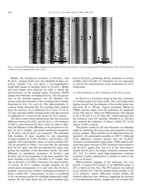
Fig. 6. Z-contrast STEM image <strong>of</strong> the intergrown structure <strong>of</strong> Zr 2 Al 3 C 4 <strong>and</strong> Zr 3 Al 3 C 5 : (a) raw image <strong>and</strong> (b) FFT filtered image. There can be either two<br />
or three Zr layers separating the Al 3 C 2 units.<br />
Besides the intergrown structure <strong>of</strong> Zr 2 Al 3 C 4 <strong>and</strong><br />
Zr 3 Al 3 C 5 , stacking faults were also identified in these two<br />
ternary carbides. Fig. 7(a) shows a low-magnification<br />
bright-field image <strong>of</strong> stacking faults in Zr 3 Al 3 C 5 . Bright<br />
<strong>and</strong> dark fringes were observed. In order to clarify the<br />
microstructure <strong>of</strong> the stacking faults, Z-contrast STEM<br />
images were obtained. As displayed in Fig. 7(b), the periodicity<br />
<strong>of</strong> the stacking sequence was not identical. The<br />
atomic-<strong>scale</strong> microstructure <strong>of</strong> the stacking faults is further<br />
illustrated in Fig. 7(c) <strong>and</strong> (d). The high-resolution Z-<br />
contrast image indicated that the stacking faults resulted<br />
from the insertion <strong>of</strong> an additional Zr–C layer. Yu et al.<br />
[27] also reported similar stacking faults with the insertion<br />
<strong>of</strong> additional Ti–C layers in the ternary Ti–Si–C system.<br />
The above observations demonstrate that the structural<br />
difference between Zr 2 Al 3 C 4 <strong>and</strong> Zr 3 Al 3 C 5 is the thickness<br />
<strong>of</strong> (ZrC) m units between the Al 3 C 2 units. In order to illustrate<br />
the influence <strong>of</strong> this difference on the properties <strong>of</strong> ternary<br />
Zr–Al–C carbides, theoretical mechanical properties<br />
for Zr 2 Al 3 C 4 <strong>and</strong> Zr 3 Al 3 C 5 are compared. The calculated<br />
bulk modulus B, shear modulus G, <strong>and</strong> anisotropic<br />
Young’s modulus E <strong>of</strong> ZrC, Zr 2 Al 3 C 4 , <strong>and</strong> Zr 3 Al 3 C 5 [28],<br />
together with experimental values for polycrystalline ZrC<br />
[29] are presented in Table 1. It is seen that the calculated<br />
data for ZrC agree well with the experimental values, suggesting<br />
the reliability <strong>of</strong> the theoretical results. The main<br />
difference in mechanical properties <strong>of</strong> Zr 2 Al 3 C 4 <strong>and</strong><br />
Zr 3 Al 3 C 5 lies in the magnitude <strong>of</strong> the shear modulus. The<br />
shear modulus <strong>of</strong> Zr 3 Al 3 C 5 (166 GPa) is 37% higher than<br />
that <strong>of</strong> Zr 2 Al 3 C 4 (121 GPa). Therefore, the shear modulus<br />
<strong>of</strong> ternary Zr–Al–C carbides strongly depends on the<br />
atomic-<strong>scale</strong> arrangements. It is also seen that Zr 3 Al 3 C 5<br />
properly conserves the excellent mechanical properties <strong>of</strong><br />
binary carbide ZrC. Consequently, Zr 3 Al 3 C 5 is predicted<br />
to be a promising carbide for ultrahigh-temperature applications.<br />
On the other h<strong>and</strong>, the low shear modulus may<br />
lead to Zr 2 Al 3 C 4 possessing similar properties to ternary<br />
carbides such as Ti 3 AlC 2 [3]. Therefore, it is very important<br />
to control the microstructure in the synthesized Zr–Al–C<br />
compounds.<br />
3.3. Determination <strong>of</strong> ZrC inclusions in Zr 3 Al 3 C 5 grains<br />
As shown in a Z-contrast image in Fig. 8(a), inclusions<br />
<strong>of</strong> rounded grains have been found. The contrasting white<br />
regions showed that the diameter <strong>of</strong> the circular grains ranged<br />
from 20 to 200 nm. Typical nanobeam diffraction<br />
(NBD) patterns taken from the inclusions are displayed<br />
in Fig. 8(b) <strong>and</strong> (c). These two NBD patterns were indexed<br />
to be [110] <strong>and</strong> [111] <strong>of</strong> cubic ZrC, which indicated that<br />
the inclusions were ZrC particles. Morgiel et al. [30] have<br />
also reported the inclusions <strong>of</strong> binary carbide TiC in the<br />
ternary Ti 3 SiC 2 ceramic.<br />
The present results for the microstructure are definitely<br />
useful in optimizing the processing <strong>and</strong> properties <strong>of</strong> these<br />
ternary carbides. Both carbides can be fabricated from elemental<br />
Zr, Al, <strong>and</strong> graphite powders at 1700 °C. Although<br />
X-ray diffraction analysis showed that the Zr 3 Al 3 C 5<br />
obtained is predominantly single phase, TEM analysis indicated<br />
that minor amounts <strong>of</strong> ZrC inclusions were present in<br />
the Zr 3 Al 3 C 5 grains (Fig. 8(a)–(c)). It has been demonstrated<br />
that Zr 3 Al 3 C 5 has higher oxidation resistance than<br />
ZrC [14]. To achieve good high-temperature oxidation<br />
resistance, further optimization is needed to improve the<br />
purity <strong>of</strong> Zr 3 Al 3 C 5 .<br />
High-resolution imaging <strong>of</strong> the inclusions was conducted.<br />
A typical FFT pattern <strong>of</strong> an HRTEM image <strong>of</strong><br />
ZrC is shown in Fig. 9(a). The FFT pattern was indexed<br />
to be twinned ZrC with the incident beam parallel to the<br />
[110] direction. Linear diffraction streaks besides the<br />
twinned reflections were observed, suggesting the presence<br />
<strong>of</strong> two-dimensional defects. Insight into the twinned ZrC


