Atomic-scale microstructures of Zr2Al3C4 and Zr3Al3C5 ceramics
Atomic-scale microstructures of Zr2Al3C4 and Zr3Al3C5 ceramics
Atomic-scale microstructures of Zr2Al3C4 and Zr3Al3C5 ceramics

Create successful ePaper yourself
Turn your PDF publications into a flip-book with our unique Google optimized e-Paper software.
Acta Materialia 54 (2006) 3843–3851<br />
www.actamat-journals.com<br />
<strong>Atomic</strong>-<strong>scale</strong> <strong>microstructures</strong> <strong>of</strong> Zr 2 Al 3 C 4 <strong>and</strong> Zr 3 Al 3 C 5 <strong>ceramics</strong><br />
Z.J. Lin a,b , M.J. Zhuo a,b , L.F. He a,b , Y.C. Zhou a, *, M.S. Li a , J.Y. Wang a<br />
a Shenyang National Laboratory for Materials Science, Institute <strong>of</strong> Metal Research, Chinese Academy <strong>of</strong> Sciences,<br />
72 Wenhua Road, Shenyang, Liaoning 110016, China<br />
b Graduate School <strong>of</strong> Chinese Academy <strong>of</strong> Sciences, Beijing 100039, China<br />
Received 11 December 2005; received in revised form 19 February 2006; accepted 24 February 2006<br />
Available online 27 June 2006<br />
Abstract<br />
The <strong>microstructures</strong> <strong>of</strong> bulk Zr 2 Al 3 C 4 <strong>and</strong> Zr 3 Al 3 C 5 <strong>ceramics</strong> have been investigated using transmission electron microscopy <strong>and</strong><br />
scanning transmission electron microscopy. These two carbides were determined to have a point group 6/mmm <strong>and</strong> a space group<br />
P6 3 /mmc using selected-area electron diffraction <strong>and</strong> convergent beam electron diffraction. The atomic-<strong>scale</strong> <strong>microstructures</strong> <strong>of</strong> Zr 2 Al 3 C 4<br />
<strong>and</strong> Zr 3 Al 3 C 5 were investigated through high-resolution imaging <strong>and</strong> Z-contrast imaging. Furthermore, intergrowth between Zr 2 Al 3 C 4<br />
<strong>and</strong> Zr 3 Al 3 C 5 was identified. Stacking faults in Zr 3 Al 3 C 5 were found to result from the insertion <strong>of</strong> an additional Zr–C layer. Cubic ZrC<br />
was occasionally identified to be incorporated in elongated Zr 3 Al 3 C 5 grains. In addition, Al may induce a twinned ZrC structure <strong>and</strong> lead<br />
to the formation <strong>of</strong> ternary zirconium aluminum carbides.<br />
Ó 2006 Acta Materialia Inc. Published by Elsevier Ltd. All rights reserved.<br />
Keywords: TEM; Carbides; Layered structures; STEM<br />
1. Introduction<br />
* Corresponding author. Tel.: +86 24 23971765; fax: +86 24 23891320.<br />
E-mail address: yczhou@imr.ac.cn (Y.C. Zhou).<br />
Binary transition metal carbides (TMCs), such as TiC,<br />
NbC, <strong>and</strong> ZrC, exhibit excellent mechanical <strong>and</strong> chemical<br />
properties, which make them suitable for diverse applications<br />
[1]. These carbides possess a high melting point, high<br />
hardness, high strength, high wear resistance, <strong>and</strong> chemical<br />
inertness. However, the poor oxidation resistance <strong>and</strong><br />
intrinsic brittleness restrict their extensive applications in<br />
high-temperature environments [1]. The toughness <strong>and</strong><br />
high-temperature oxidation resistance <strong>of</strong> TiC <strong>and</strong> NbC<br />
can be greatly improved by forming ternary aluminum carbides,<br />
such as Ti 3 AlC 2 ,Ti 2 AlC, <strong>and</strong> Nb 2 AlC [2–6]. Furthermore,<br />
a series <strong>of</strong> new ternary aluminum carbides in<br />
Ti–Al–C, Nb–Al–C, Zr–Al–C, <strong>and</strong> Hf–Al–C systems have<br />
been successfully synthesized using transition metals, aluminum,<br />
<strong>and</strong> graphite as starting materials [7,8]. Successes<br />
with the Ti–Al–C <strong>and</strong> Nb–Al–C systems highlighted a possible<br />
way to overcome difficulties in the applications <strong>of</strong><br />
ZrC.<br />
Ternary aluminum carbides in Ti–Al–C <strong>and</strong> Nb–Al–C<br />
systems, such as Ti 3 AlC 2 <strong>and</strong> Nb 2 AlC, have been identified<br />
to crystallize in P6 3 /mmc symmetry [2,8]. Their crystal<br />
structures can be described as non-stoichiometric TiC x<br />
(or NbC x ) units in NaCl-type structure being intercalated<br />
<strong>and</strong> mirrored by close-packed Al atomic planes. These ternary<br />
aluminum carbides have attractive properties, such as<br />
easy machinability, damage tolerance, excellent high-temperature<br />
oxidation resistance, <strong>and</strong> good electrical <strong>and</strong> thermal<br />
conductivities, due to their nano-laminated structures<br />
[6]. Moreover, these ternary carbides properly conserve<br />
the desired high moduli <strong>and</strong> strength <strong>of</strong> their binary<br />
counterparts.<br />
Two ternary carbides, i.e. Zr 2 Al 3 C 4 <strong>and</strong> Zr 3 Al 3 C 5 (previously<br />
reported with the chemical formula <strong>of</strong> Zr 2 Al 3 C 5 x<br />
<strong>and</strong> ZrAlC 2 x , respectively [8]), were determined to have<br />
hexagonal symmetry in the ternary Zr–Al–C system<br />
[9,10]. Compared with those well-studied <strong>ceramics</strong> in the<br />
Ti–Al–C <strong>and</strong> Nb–Al–C systems, ternary Zr–Al–C compounds<br />
have been less investigated. The reasons can be<br />
1359-6454/$30.00 Ó 2006 Acta Materialia Inc. Published by Elsevier Ltd. All rights reserved.<br />
doi:10.1016/j.actamat.2006.02.052
3844 Z.J. Lin et al. / Acta Materialia 54 (2006) 3843–3851<br />
attributed to difficulties in synthesizing bulk materials <strong>and</strong><br />
lack <strong>of</strong> knowledge <strong>of</strong> the microstructural characteristics<br />
<strong>and</strong> mechanical <strong>and</strong> chemical properties.<br />
Hashimoto et al. [11] fabricated Zr 3 Al 3 C 5 -based composites<br />
<strong>and</strong> reported that the composites displayed satisfactory<br />
oxidation resistance. Recently, Leela-adisorn et al.<br />
[12,13] fabricated bulk Zr 2 Al 3 C 4 <strong>and</strong> Zr 3 Al 3 C 5 from the<br />
corresponding compound powders which were prepared<br />
by solid-state reaction <strong>of</strong> ZrC, Al, <strong>and</strong> graphite. The fracture<br />
strength <strong>and</strong> Vickers hardness were tentatively characterized<br />
for Zr 3 Al 3 C 5 . He et al. [14] synthesized Zr 3 Al 3 C 5<br />
powders using Zr–Al intermetallics <strong>and</strong> graphite as starting<br />
materials. Oxidation tests indicated that Zr 3 Al 3 C 5 powders<br />
displayed higher oxidation resistance than ZrC [14].<br />
Despite these achievements, the structural information<br />
for Zr 2 Al 3 C 4 <strong>and</strong> Zr 3 Al 3 C 5 is very limited <strong>and</strong> confused.<br />
Using X-ray diffraction analysis, the space group <strong>of</strong><br />
Zr 2 Al 3 C 4 was reported to be P31 c (C 4 3vÞ by Schuster <strong>and</strong><br />
Nowotny [8], P6 3 /mmc by Parthé <strong>and</strong> Chabot [10], <strong>and</strong><br />
P6 3 mc by Fukuda et al. [15]. Similarly, Zr 3 Al 3 C 5 has been<br />
reported to have P6 3 /mmc [8,9] <strong>and</strong> P6 3 mc symmetry [16].<br />
Therefore, it is necessary to clarify the symmetry <strong>of</strong> both<br />
carbides. Furthermore, atomic-<strong>scale</strong> <strong>microstructures</strong> are<br />
valuable in underst<strong>and</strong>ing the structures <strong>and</strong> properties<br />
<strong>of</strong> these two ternary carbides.<br />
In this work, the microstructural characterizations <strong>of</strong><br />
two ternary Zr–Al–C <strong>ceramics</strong> were carried out by means<br />
<strong>of</strong> transmission electron microscopy (TEM) <strong>and</strong> scanning<br />
transmission electron microscopy (STEM). The symmetry<br />
<strong>of</strong> both carbides was determined using selected-area electron<br />
diffraction (SAED) <strong>and</strong> convergent beam electron diffraction<br />
(CBED). <strong>Atomic</strong>-<strong>scale</strong> <strong>microstructures</strong> <strong>of</strong> both<br />
carbides were characterized <strong>and</strong> are discussed in this paper.<br />
which was equipped with a high-angle annular dark-field<br />
(HAADF) detector in the STEM system <strong>and</strong> a postcolumn<br />
Gatan imaging filter system, was used for highresolution<br />
imaging <strong>and</strong> Z-contrast STEM imaging. Fast<br />
Fourier transformation (FFT) was carried out using a<br />
DigitalMicrograph s<strong>of</strong>tware package.<br />
3. Results <strong>and</strong> discussion<br />
3.1. Symmetry determination <strong>of</strong> Zr 2 Al 3 C 4 <strong>and</strong> Zr 3 Al 3 C 5<br />
Fig. 1(a) <strong>and</strong> (b) show the crystal structures <strong>of</strong> Zr 2 Al 3 C 4<br />
<strong>and</strong> Zr 3 Al 3 C 5 , respectively [8,10]. The atomic arrangements<br />
<strong>of</strong> these two carbides are further illustrated in Fig. 1(c) <strong>and</strong><br />
(d) using two 2 · 2 · 1 slices on the ð1 210Þ plane. As<br />
described by Gesing <strong>and</strong> Jeitschko [16] <strong>and</strong> by Fukuda<br />
et al. [15], Zr 2 Al 3 C 4 <strong>and</strong> Zr 3 Al 3 C 5 can be viewed as inter-<br />
2. Experimental<br />
Bulk Zr 2 Al 3 C 4 <strong>and</strong> Zr 3 Al 3 C 5 <strong>ceramics</strong> were prepared<br />
through a hot pressing method using elemental powders<br />
<strong>of</strong> zirconium (99% purity, 400 mesh), aluminum (99%<br />
purity, 200 mesh), <strong>and</strong> graphite (99% purity, 200 mesh)<br />
as starting materials. Powder mixtures <strong>of</strong> appropriate stoichiometry<br />
were homogenized using ethanol as a mixing<br />
medium in a planetary ball mill for 12 h <strong>and</strong> then dried<br />
at room temperature for 24 h. Afterwards, the mixed powders<br />
were uniaxially pressed under a pressure <strong>of</strong> 10 MPa in<br />
a BN-coated graphite mold <strong>of</strong> 25 mm in diameter. The<br />
compacted mixture was heated to 1700 °C at a heating rate<br />
<strong>of</strong> 15 °C/min <strong>and</strong> then hot pressed for 1 h in a flowing Ar<br />
atmosphere. The applied pressure was 35 MPa during the<br />
synthesis <strong>of</strong> both carbides. The surface layers <strong>of</strong> the samples<br />
were machined <strong>of</strong>f using a SiC grinding wheel to<br />
remove contaminants arising from the graphite mold.<br />
Thin-foil specimens for TEM observations were prepared<br />
by slicing, mechanical grinding to 20 lm, dimpling<br />
down to 10 lm, <strong>and</strong> ion milling at 4.0 kV. A 200 kV<br />
JEM-2010 TEM instrument was used for SAED <strong>and</strong><br />
CBED analysis. A 300 kV Tecnai G 2 F30 TEM instrument,<br />
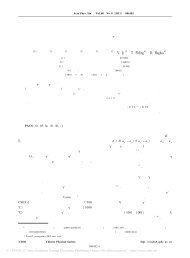
Fig. 1. Crystal structures <strong>of</strong>: (a) Zr 2 Al 3 C 4 <strong>and</strong> (b) Zr 3 Al 3 C 5 . <strong>Atomic</strong><br />
arrangements <strong>of</strong> two 2 · 2 · 1 slices on the ð1 210Þ plane <strong>of</strong> (c) Zr 2 Al 3 C 4<br />
<strong>and</strong> (d) Zr 3 Al 3 C 5 . The main difference between these two carbides centers<br />
on the (ZrC) m units.
Z.J. Lin et al. / Acta Materialia 54 (2006) 3843–3851 3845<br />
growth structures consisting <strong>of</strong> two kinds <strong>of</strong> layers. One is<br />
the non-stoichiometric (ZrC) m (m = 2 or 3) slab in the<br />
NaCl-type structure <strong>and</strong> the other consists <strong>of</strong> Al 3 C 2 units<br />
in an arrangement similar to that <strong>of</strong> the binary aluminum<br />
carbide Al 4 C 3 . The structural difference is that m = 2 for<br />
Zr 2 Al 3 C 4 , while m = 3 for Zr 3 Al 3 C 5 .<br />
The combination <strong>of</strong> SAED <strong>and</strong> CBED has been successfully<br />
used in determining the symmetry <strong>of</strong> ternary carbides<br />
such as Ti 3 SiC 2 [17] <strong>and</strong> Ti 3 AlC 2 [18]. Therefore, these two<br />
methods were used to identify the symmetry <strong>of</strong> ternary Zr–<br />
Al–C carbides in this work. Fig. 2(a)–(c) show SAED patterns<br />
which were indexed as [0001], ½1 210Š, <strong>and</strong> ½1 100Š<br />
zone axes, respectively, <strong>of</strong> the hexagonal Zr 2 Al 3 C 4 . From<br />
these patterns <strong>of</strong> low-indices basic zone axes, the lattice<br />
parameters were derived as a = 0.33 nm <strong>and</strong> c = 2.24 nm,<br />
which were consistent with those determined from powder<br />
X-ray analysis [8,14,15]. These SAED patterns were also<br />
informative for learning extinction rules. It is noted that<br />
all reflections in the ½1 210Š pattern appeared, but the<br />
(000l) (l = odd) reflections in the ½1 100Š pattern were<br />
absent, implying the existence <strong>of</strong> a c glide plane. The<br />
appearance <strong>of</strong> the {0 00l} (l = odd) reflections in the<br />
½1 210Š pattern can be attributed to double diffraction<br />
[18–20]. Fig. 2(d) shows an SAED pattern whose orientation<br />
was positioned between ½1 210Š <strong>and</strong> ½1 100Š. As shown<br />
in Fig. 2(d), the (000l) reflections with l = odd were also<br />
absent which indicated that there was a 6 3 screw axis along<br />
the [0001] axis [18,19]. Fig. 2(e) shows a CBED pattern<br />
obtained from a Zr 2 Al 3 C 4 grain along the [0001] zone axis.<br />
A sixfold axis <strong>of</strong> rotational symmetry as well as two independent<br />
<strong>and</strong> mutually perpendicular mirror planes (each <strong>of</strong><br />
which is reproduced every 60° by the action <strong>of</strong> the sixfold<br />
axis) were observed. These two types <strong>of</strong> mirror planes are<br />
parallel to the sixfold axis. The symmetry was determined<br />
to be 6mm. In addition, the symmetry shown in the SAED<br />
½1 210Š pattern (Fig. 2(b)) was 2mm. A6mm symmetry <strong>and</strong><br />
a2mm symmetry indicate a unique 6/mmm point group for<br />
Zr 2 Al 3 C 4 [17–19]. Fig. 2(f) shows a CBED pattern showing<br />
the existence <strong>of</strong> a mirror plane on (0001). A 6mm symmetry<br />
<strong>and</strong> a mirror plane on (0001) further confirm the<br />
6/mmm point group for Zr 2 Al 3 C 4 . A combination <strong>of</strong> the<br />
information derived from these SAED <strong>and</strong> CBED patterns<br />
indicate that Zr 2 Al 3 C 4 has a space group P6 3 /mmc, which<br />
agrees well with the results <strong>of</strong> Parthé <strong>and</strong> Chabot [10].<br />
Fig. 2. (a–c) SAED patterns <strong>of</strong> hexagonal Zr 2 Al 3 C 4 with the electron beam parallel to the directions <strong>of</strong> [0001], ½1 210Š, <strong>and</strong> ½1 100Š, respectively. (d) An<br />
SAED pattern with the orientation being positioned between ½1 210Š <strong>and</strong> ½1 100Š. (e) A CBED pattern showing the symmetry <strong>of</strong> a sixfold rotation about<br />
the [0001] axis <strong>and</strong> also the symmetry <strong>of</strong> the mirror reflection across two independent planes. (f) A CBED pattern showing the existence <strong>of</strong> a mirror plane<br />
on (0001).
3846 Z.J. Lin et al. / Acta Materialia 54 (2006) 3843–3851<br />
The symmetry <strong>of</strong> Zr 3 Al 3 C 5 was also determined using<br />
SAED <strong>and</strong> CBED. The lattice parameters obtained were<br />
a = 0.33 nm <strong>and</strong> c = 2.76 nm, which are in good agreement<br />
with previously reported data [9,16]. Zr 3 Al 3 C 5 was also<br />
determined to have a point group 6/mmm <strong>and</strong> a space<br />
group P6 3 /mmc, which is consistent with that reported by<br />
Mikhalenko et al. [8,9]. The SAED <strong>and</strong> CBED patterns<br />
<strong>of</strong> Zr 3 Al 3 C 5 were similar to those <strong>of</strong> Zr 2 Al 3 C 4 <strong>and</strong> are<br />
therefore not shown for brevity.<br />
3.2. Microstructure <strong>of</strong> hexagonal Zr 2 Al 3 C 4 <strong>and</strong> Zr 3 Al 3 C 5<br />
Fig. 3(a) <strong>and</strong> (b) display the low-magnification brightfield<br />
TEM images <strong>of</strong> Zr 2 Al 3 C 4 <strong>and</strong> Zr 3 Al 3 C 5 , respectively.<br />
The overall characteristics <strong>of</strong> the <strong>microstructures</strong> <strong>of</strong> the assynthesized<br />
<strong>ceramics</strong> can be observed. Extensive TEM<br />
observations have shown that the Zr 2 Al 3 C 4 grains had salient<br />
features, i.e. the grains generally had elongated morphologies<br />
ranging from 2 to 20 lm in length <strong>and</strong> 30 to<br />
500 nm in width in the perpendicular direction. SAED<br />
analysis revealed that the crystallographic direction<br />
[0001] <strong>of</strong> Zr 2 Al 3 C 4 was perpendicular to the elongated<br />
direction <strong>of</strong> the Zr 2 Al 3 C 4 grains. Rotations between grains<br />
were found to be along the [0001] axis <strong>and</strong> along the direction<br />
perpendicular to [0001]. Most <strong>of</strong> the grain boundaries<br />
were large-angle grain boundaries; <strong>and</strong> grains with misorientation<br />
<strong>of</strong> only several degrees were also observed. In contrast,<br />
the Zr 3 Al 3 C 5 grains were less regular as displayed in<br />
Fig. 3(b). In addition, some grains were found to crystallize<br />
in the form <strong>of</strong> elongated slabs, which were similar to those<br />
in Zr 2 Al 3 C 4 .<br />
It is generally believed that elongated grains with large<br />
aspect ratio would benefit the toughness <strong>of</strong> <strong>ceramics</strong>. For<br />
example, elongated Si 3 N 4 grains were effective in toughening<br />
a ceramic by crack deflection <strong>and</strong> crack bridging<br />
[21,22].SoZr 2 Al 3 C 4 with elongated grains may display better<br />
toughness than Zr 3 Al 3 C 5 . The difference <strong>of</strong> grain morphologies<br />
between Zr 2 Al 3 C 4 <strong>and</strong> Zr 3 Al 3 C 5 may originate<br />
from the different liquid phase content during the synthesizing<br />
processes. It is possible that the relatively higher<br />
liquid phase during the synthesis <strong>of</strong> Zr 2 Al 3 C 4 favors the<br />
formation <strong>of</strong> elongated grains. During the synthesis <strong>of</strong><br />
Si 3 N 4 , Perera et al. [22] have shown that sintering additives<br />
strongly influence the grain morphologies <strong>of</strong> the <strong>ceramics</strong><br />
by controlling the liquid phase content. Their work may<br />
support our hypothesis.<br />
Fig. 4 shows a high-resolution TEM (HRTEM) image<br />
<strong>of</strong> Zr 2 Al 3 C 4 obtained with the incident beam parallel to<br />
the ½1 210Š direction. The image fringes with a periodicity<br />
<strong>of</strong> 2.24 nm along the [0001] direction can be clearly seen.<br />
The C atoms cannot be resolved in the microscopes<br />
because <strong>of</strong> its weak diffraction power. The bright spots<br />
can be described as a layered stacking with a sequence <strong>of</strong><br />
ABCBACBABC along the [0001] direction. This type <strong>of</strong><br />
stacking sequence corresponds to the Zr <strong>and</strong> Al atoms in<br />
the Zr 2 Al 3 C 4 structure <strong>and</strong> is consistent with the structure<br />
previously proposed by Parthé <strong>and</strong> Chabot [10].<br />
Unfortunately, the atomic positions <strong>of</strong> Zr <strong>and</strong> Al cannot<br />
be distinguished using conventional HRTEM because this<br />
technique uses phase-contrast imaging.<br />
Z-contrast STEM imaging, which was developed by<br />
Pennycook <strong>and</strong> co-workers [23,24], can efficiently<br />
distinguish different atoms because this technique uses<br />
high-angle inelastic electrons. This technique removes the<br />
coherent effects <strong>of</strong> diffraction <strong>and</strong> leads to strong atomic<br />
number, Z, contrast. The intensity <strong>of</strong> the obtained image<br />
is proportional to Z 2 , the square <strong>of</strong> atomic number.<br />
Therefore, Z-contrast STEM images are more directly<br />
Fig. 3. Typical TEM bright-field images <strong>of</strong>: (a) Zr 2 Al 3 C 4 <strong>and</strong> (b) Zr 3 Al 3 C 5 . The Zr 2 Al 3 C 4 grains generally have elongated morphologies while the<br />
Zr 3 Al 3 C 5 grains are irregular.
Z.J. Lin et al. / Acta Materialia 54 (2006) 3843–3851 3847<br />
Fig. 4. HRTEM image <strong>of</strong> Zr 2 Al 3 C 4 obtained with the incident beam<br />
parallel to the ½1 210Š direction.<br />
interpretable than conventional phase-contrast images <strong>and</strong><br />
this method was used to determine the positions <strong>of</strong> Al <strong>and</strong><br />
Zr in ternary Zr–Al–C carbides. Fig. 5(a) displays a raw<br />
high-resolution Z-contrast STEM image <strong>of</strong> Zr 2 Al 3 C 4<br />
viewed along the ½1 210Š direction. The main experimental<br />
parameters were a probe size <strong>of</strong> 0.17 nm <strong>and</strong> detector semiangles<br />
<strong>of</strong> 36–100 mrad. An inner detector semi-angle <strong>of</strong><br />
36 mrad was used for the following two reasons. Firstly,<br />
Pennycook <strong>and</strong> co-workers [25] proposed that the detector<br />
semi-angle depends on the electron wavelength <strong>and</strong> point<br />
resolution. A criterion <strong>of</strong> semi-angle to obtain incoherent<br />
images can be described by the following equation:<br />
b > 1:22k=DR<br />
ð1Þ<br />
where b is the semi-angle, k is the electron wavelength, <strong>and</strong><br />
DR is the point resolution <strong>of</strong> the TEM. In this work, a<br />
Tecnai G 2 F30 TEM instrument working at 300 kV was<br />
used for Z-contrast imaging. k <strong>and</strong> DR are 0.0197 <strong>and</strong><br />
1.7 Å, respectively. As a result, 1.22k/DR = 14.1 mrad.<br />
Consequently, incoherent images can be obtained with an<br />
inner angle larger than 14.1 mrad in the present system.<br />
Secondly, the atomic number <strong>of</strong> Zr (Z = 40) is relatively<br />
large; in order to reduce the coherent effect <strong>of</strong> Zr atomic<br />
columns, an inner detector semi-angle <strong>of</strong> 36 mrad was used.<br />
The atomic positions <strong>of</strong> Zr <strong>and</strong> Al were clearly characterized<br />
in the Z-contrast image since the intensity <strong>of</strong> a spot reflects<br />
the atomic number <strong>of</strong> the corresponding atom. As<br />
shown in Fig. 5(b), an important feature <strong>of</strong> Zr 3 Al 3 C 5 is that<br />
the three Zr layers separate the Al 3 C 2 units, as well as two<br />
Zr layers in Zr 2 Al 3 C 4 . This is consistent with the crystal<br />
structures shown in Fig. 1.<br />
Fig. 6(a) shows an intergrown structure between<br />
Zr 2 Al 3 C 4 <strong>and</strong> Zr 3 Al 3 C 5 . The corresponding FFT filtered<br />
image <strong>of</strong> Fig. 6(a) is displayed in Fig. 6(b) The intergrowth<br />
between these two carbides can be understood as follows.<br />
The lattice parameters a <strong>of</strong> Zr 2 Al 3 C 4 (0.3346 nm) [10]<br />
<strong>and</strong> Zr 3 Al 3 C 5 (0.3347 nm) [9] are essentially equal, which<br />
ensures an intergrowth with negligible lattice misfit; in<br />
addition, Zr 2 Al 3 C 4 shares a similar crystal structure with<br />
Zr 3 Al 3 C 5 with the only difference centering on the (ZrC) m<br />
units. Locally, enrichment <strong>of</strong> Zr in Zr 2 Al 3 C 4 may lead to<br />
the formation <strong>of</strong> Zr 3 Al 3 C 5 . Similar intergrown structures<br />
have been identified in the ternary Ti–Al–C [18,20] <strong>and</strong><br />
Ti–Si–C [26] systems.<br />
Fig. 5. High-resolution Z-contrast STEM images viewed along the ½1 210Š direction <strong>of</strong>: (a) Zr 2 Al 3 C 4 <strong>and</strong> (b) Zr 3 Al 3 C 5 .
3848 Z.J. Lin et al. / Acta Materialia 54 (2006) 3843–3851<br />
Fig. 6. Z-contrast STEM image <strong>of</strong> the intergrown structure <strong>of</strong> Zr 2 Al 3 C 4 <strong>and</strong> Zr 3 Al 3 C 5 : (a) raw image <strong>and</strong> (b) FFT filtered image. There can be either two<br />
or three Zr layers separating the Al 3 C 2 units.<br />
Besides the intergrown structure <strong>of</strong> Zr 2 Al 3 C 4 <strong>and</strong><br />
Zr 3 Al 3 C 5 , stacking faults were also identified in these two<br />
ternary carbides. Fig. 7(a) shows a low-magnification<br />
bright-field image <strong>of</strong> stacking faults in Zr 3 Al 3 C 5 . Bright<br />
<strong>and</strong> dark fringes were observed. In order to clarify the<br />
microstructure <strong>of</strong> the stacking faults, Z-contrast STEM<br />
images were obtained. As displayed in Fig. 7(b), the periodicity<br />
<strong>of</strong> the stacking sequence was not identical. The<br />
atomic-<strong>scale</strong> microstructure <strong>of</strong> the stacking faults is further<br />
illustrated in Fig. 7(c) <strong>and</strong> (d). The high-resolution Z-<br />
contrast image indicated that the stacking faults resulted<br />
from the insertion <strong>of</strong> an additional Zr–C layer. Yu et al.<br />
[27] also reported similar stacking faults with the insertion<br />
<strong>of</strong> additional Ti–C layers in the ternary Ti–Si–C system.<br />
The above observations demonstrate that the structural<br />
difference between Zr 2 Al 3 C 4 <strong>and</strong> Zr 3 Al 3 C 5 is the thickness<br />
<strong>of</strong> (ZrC) m units between the Al 3 C 2 units. In order to illustrate<br />
the influence <strong>of</strong> this difference on the properties <strong>of</strong> ternary<br />
Zr–Al–C carbides, theoretical mechanical properties<br />
for Zr 2 Al 3 C 4 <strong>and</strong> Zr 3 Al 3 C 5 are compared. The calculated<br />
bulk modulus B, shear modulus G, <strong>and</strong> anisotropic<br />
Young’s modulus E <strong>of</strong> ZrC, Zr 2 Al 3 C 4 , <strong>and</strong> Zr 3 Al 3 C 5 [28],<br />
together with experimental values for polycrystalline ZrC<br />
[29] are presented in Table 1. It is seen that the calculated<br />
data for ZrC agree well with the experimental values, suggesting<br />
the reliability <strong>of</strong> the theoretical results. The main<br />
difference in mechanical properties <strong>of</strong> Zr 2 Al 3 C 4 <strong>and</strong><br />
Zr 3 Al 3 C 5 lies in the magnitude <strong>of</strong> the shear modulus. The<br />
shear modulus <strong>of</strong> Zr 3 Al 3 C 5 (166 GPa) is 37% higher than<br />
that <strong>of</strong> Zr 2 Al 3 C 4 (121 GPa). Therefore, the shear modulus<br />
<strong>of</strong> ternary Zr–Al–C carbides strongly depends on the<br />
atomic-<strong>scale</strong> arrangements. It is also seen that Zr 3 Al 3 C 5<br />
properly conserves the excellent mechanical properties <strong>of</strong><br />
binary carbide ZrC. Consequently, Zr 3 Al 3 C 5 is predicted<br />
to be a promising carbide for ultrahigh-temperature applications.<br />
On the other h<strong>and</strong>, the low shear modulus may<br />
lead to Zr 2 Al 3 C 4 possessing similar properties to ternary<br />
carbides such as Ti 3 AlC 2 [3]. Therefore, it is very important<br />
to control the microstructure in the synthesized Zr–Al–C<br />
compounds.<br />
3.3. Determination <strong>of</strong> ZrC inclusions in Zr 3 Al 3 C 5 grains<br />
As shown in a Z-contrast image in Fig. 8(a), inclusions<br />
<strong>of</strong> rounded grains have been found. The contrasting white<br />
regions showed that the diameter <strong>of</strong> the circular grains ranged<br />
from 20 to 200 nm. Typical nanobeam diffraction<br />
(NBD) patterns taken from the inclusions are displayed<br />
in Fig. 8(b) <strong>and</strong> (c). These two NBD patterns were indexed<br />
to be [110] <strong>and</strong> [111] <strong>of</strong> cubic ZrC, which indicated that<br />
the inclusions were ZrC particles. Morgiel et al. [30] have<br />
also reported the inclusions <strong>of</strong> binary carbide TiC in the<br />
ternary Ti 3 SiC 2 ceramic.<br />
The present results for the microstructure are definitely<br />
useful in optimizing the processing <strong>and</strong> properties <strong>of</strong> these<br />
ternary carbides. Both carbides can be fabricated from elemental<br />
Zr, Al, <strong>and</strong> graphite powders at 1700 °C. Although<br />
X-ray diffraction analysis showed that the Zr 3 Al 3 C 5<br />
obtained is predominantly single phase, TEM analysis indicated<br />
that minor amounts <strong>of</strong> ZrC inclusions were present in<br />
the Zr 3 Al 3 C 5 grains (Fig. 8(a)–(c)). It has been demonstrated<br />
that Zr 3 Al 3 C 5 has higher oxidation resistance than<br />
ZrC [14]. To achieve good high-temperature oxidation<br />
resistance, further optimization is needed to improve the<br />
purity <strong>of</strong> Zr 3 Al 3 C 5 .<br />
High-resolution imaging <strong>of</strong> the inclusions was conducted.<br />
A typical FFT pattern <strong>of</strong> an HRTEM image <strong>of</strong><br />
ZrC is shown in Fig. 9(a). The FFT pattern was indexed<br />
to be twinned ZrC with the incident beam parallel to the<br />
[110] direction. Linear diffraction streaks besides the<br />
twinned reflections were observed, suggesting the presence<br />
<strong>of</strong> two-dimensional defects. Insight into the twinned ZrC
Z.J. Lin et al. / Acta Materialia 54 (2006) 3843–3851 3849<br />
Fig. 7. (a) Low-magnification bright-field image <strong>of</strong> stacking faults <strong>of</strong> Zr 3 Al 3 C 5 . (b) Medium-magnification Z-contrast image showing the periodicity <strong>of</strong> the<br />
stacking faults. (c) Raw high-magnification Z-contrast STEM image <strong>of</strong> a stacking fault resulting from the insertion <strong>of</strong> an additional ZrC layer. (d) FFT<br />
filtered image <strong>of</strong> (c). The arrows in (b) indicate the stacking faults.<br />
Table 1<br />
Calculated bulk modulus B, shear modulus G, <strong>and</strong> anisotropic Young’s<br />
modulus E <strong>of</strong> ZrC, Zr 2 Al 3 C 4 , <strong>and</strong> Zr 3 Al 3 C 5 , together with experimental<br />
values for polycrystalline ZrC for comparison<br />
Method B (GPa) G (GPa) E (GPa)<br />
ZrC Calc. [28] 229 170 408<br />
Expt. [29] 223 170 407<br />
Zr 2 Al 3 C 4 Calc. [28] 190 121 E x = 356<br />
E y = 302<br />
Zr 3 Al 3 C 5 Calc. [28] 202 166 E x = 388<br />
E y = 346<br />
microstructure showed that a very thin Al platelet with several<br />
atomic layers was present at the ZrC twin boundaries.<br />
A typical Z-contrast image with three Al atomic layers at a<br />
ZrC twin boundary is displayed in Fig. 9(b) <strong>and</strong> (c). The<br />
spots with higher intensity correspond to Zr <strong>and</strong> the rest<br />
denote Al. The structure <strong>of</strong> this thin Al platelet was identical<br />
to the Al 3 C 2 unit in ternary Zr–Al–C carbides, suggesting<br />
that ternary Zr–Al–C thin platelets could form at the<br />
ZrC twin boundaries.<br />
TEM investigations <strong>of</strong> bulk ZrC are very limited<br />
because <strong>of</strong> the difficulties in sintering ZrC ceramic [31].
3850 Z.J. Lin et al. / Acta Materialia 54 (2006) 3843–3851<br />
Fig. 8. (a) Z-contrast image <strong>of</strong> ZrC inclusions in an elongated Zr 3 Al 3 C 5 grain. (b, c) NBD patterns <strong>of</strong> cubic ZrC with the electron beam parallel to [110]<br />
<strong>and</strong> [111] directions.<br />
Fig. 9. (a) FFT image from a region containing ZrC twins. (b) Initial high-resolution Z-contrast STEM image <strong>of</strong> a twinned ZrC with three Al layers at the<br />
twin boundaries. (c) FFT filtered image <strong>of</strong> (b).<br />
The microstructural characteristics <strong>of</strong> TiC, another binary<br />
TMC with NaCl-type structure, have been extensively<br />
investigated [32,33]. Previous investigations showed that<br />
TiC has a high stacking fault energy. Interestingly, impurities<br />
such as Al <strong>and</strong> Si could stabilize the twinned TiC structure<br />
<strong>and</strong> induced the formation <strong>of</strong> ternary Ti–Si(Al)–C<br />
carbides [34,35]. Since ZrC <strong>and</strong> TiC have the same rocksalt<br />
structure, it is reasonable that Al can also efficiently<br />
reduce the twin boundary energy <strong>of</strong> ZrC <strong>and</strong> consequently<br />
lead to the formation <strong>of</strong> ternary Zr–Al–C carbides. It is<br />
also clear that ZrC serves as the intermediate phase during<br />
the synthesis <strong>of</strong> ternary Zr–Al–C carbides from Zr, Al, <strong>and</strong><br />
graphite elemental powders. This result leads to the interpretation<br />
that ternary Zr–Al–C carbides can be synthesized<br />
using elemental Zr, Al, <strong>and</strong> graphite powders as in this<br />
work, or ZrC <strong>and</strong> Al as in previous works [11–13].<br />
4. Conclusions<br />
The microstructural characteristics were investigated<br />
for Zr 2 Al 3 C 4 <strong>and</strong> Zr 3 Al 3 C 5 <strong>ceramics</strong>. The point group<br />
<strong>and</strong> space group <strong>of</strong> both carbides were determined to<br />
be 6/mmm <strong>and</strong> P6 3 /mmc, respectively, form SAED<br />
<strong>and</strong> CBED analyses. The lattice parameters <strong>of</strong> asprepared<br />
Zr 2 Al 3 C 4 (a = 0.33 nm <strong>and</strong> c = 2.24 nm) <strong>and</strong><br />
Zr 3 Al 3 C 5 (a = 0.33 nm <strong>and</strong> c = 2.76 nm) were<br />
obtained.<br />
The atomic-<strong>scale</strong> <strong>microstructures</strong> <strong>of</strong> these two carbides<br />
were determined through high-resolution imaging <strong>and</strong><br />
Z-contrast STEM imaging. Zr 3 Al 3 C 5 was identified to<br />
form an intergrown structure with Zr 3 Al 3 C 5 . Stacking<br />
faults in Zr 3 Al 3 C 5 resulted from the insertion <strong>of</strong> an additional<br />
Zr–C layer.
Z.J. Lin et al. / Acta Materialia 54 (2006) 3843–3851 3851<br />
Minor amounts <strong>of</strong> rounded ZrC inclusions were<br />
observed in the elongated Zr 3 Al 3 C 5 grains. Al was found<br />
to induce a twinned ZrC structure <strong>and</strong> lead to the formation<br />
<strong>of</strong> ternary Zr–Al–C carbides.<br />
Acknowledgements<br />
The authors thank Miss Y. Cui for revising this manuscript.<br />
This work was supported by the National Outst<strong>and</strong>ing<br />
Young Scientist Foundation for Y.C.Z. under Grant<br />
No. 59925208, Natural Sciences Foundation <strong>of</strong> China under<br />
Grant Nos. 50232040, 50302011, <strong>and</strong> 90403027.<br />
References<br />
[1] Nowotny H, Windisch S. Annu Rev Mater Sci 1973;3:171.<br />
[2] Pietzka MA, Schuster JC. J Phase Equilib 1994;15:392.<br />
[3] Wang XH, Zhou YC. Acta Mater 2002;50:3141.<br />
[4] Wang XH, Zhou YC. Oxid Met 2003;59:303.<br />
[5] Salama I, El-Raghy T, Barsoum MW. J Alloy Compd 2002;347:271.<br />
[6] Barsoum MW. Prog Solid State Chem 2000;28:201.<br />
[7] Schuster JC, Nowotny H, Vaccaro C. J Solid State Chem<br />
1980;32:213.<br />
[8] Schuster JC, Nowotny H. Z Metallkd 1980;71:341.<br />
[9] Mikhalenko SI, Kuz’ma YB, Popov VE, Gurin VN, Nechitailov AP.<br />
Izv Akad Nauk SSSR, Neorgan Mater 1979;15:1948.<br />
[10] Parthé E, Chabot B. Acta Crystallogr 1988;C44:774.<br />
[11] Hashimoto S, Yamaguchi A, Yasuda M. J Mater Sci 1998;33:4835.<br />
[12] Leela-adisorn U, Choi SM, Hashimoto S, Honda S, Awaji H. In:<br />
Proceedings <strong>of</strong> the 21st international Korea–Japan seminar on<br />
<strong>ceramics</strong>; 2004. p. 339.<br />
[13] Leela-adisorn U, Choi SM, Tera N, Takeuchi T, Hashimoto S,<br />
Honda S, Awaji H, Hayakawa K, Yamaguchi A. J Ceram Soc Jpn<br />
2005;113:188.<br />
[14] He LF, Zhou YC, Bao YW, Wang JY, Li MS [unpublished work].<br />
[15] Fukuda K, Mori S, Hashimoto S. J Am Ceram Soc 2005;88:3528.<br />
[16] Gesing TM, Jeitschko W. J Solid State Chem 1998;140:396.<br />
[17] Arunajatesan S, Carim AH. Mater Lett 1994;20:319.<br />
[18] Ma XL, Zhu YL, Wang XH, Zhou YC. Philos Mag 2004;84:2969.<br />
[19] Hahn T. International tables for crystallography, vol. A: space-group<br />
symmetry. Dordrecht: Kluwer; 1989.<br />
[20] Lin ZJ, Zhuo MJ, Zhou YC, Li MS, Wang JY. Acta Mater<br />
2006;54:1009.<br />
[21] Sun EY, Becher PF, Hsueh CH, Painter GS, Waters SB, Hwang SL,<br />
H<strong>of</strong>fmann MJ. Acta Mater 1999;47:2777.<br />
[22] Perera DS, Mitchell DRG, Leung S. J Eur Ceram Soc 2000;20:789.<br />
[23] Pennycook SJ, Boatner LA. Nature 1988;336:565.<br />
[24] Browning ND, Chisholm MF, Pennycook SJ. Nature 1993;366:143.<br />
[25] Pennycook SJ, Yan YF. In: Zhang Xiao-Feng, Zhang Ze, editors.<br />
Progress in transmission electron microscopy, vol. 1. Berlin:<br />
Springer; 2001. p. 86.<br />
[26] Palmquist JP, Li S, Persson POÅ, Emmerlich J, Wilhelmsson O,<br />
Högberg H, Katsnelson MI, Johansson B, Ahuja R, Eriksson O,<br />
Hultman L, Jansson U. Phys Rev B 2004;70:165401.<br />
[27] Yu R, Zhan Q, He LL, Zhou YC, Ye HQ. Philos Mag Lett<br />
2003;83:325.<br />
[28] Wang JY, Zhou YC, Lin ZJ, Liao T, He LF. Phys Rev B<br />
2006;73:134107.<br />
[29] Green DJ. An introduction to the mechanical properties <strong>of</strong> <strong>ceramics</strong>.<br />
Cambridge: Press Syndicate <strong>of</strong> the University <strong>of</strong> Cambridge; 1998.<br />
[30] Morgiel J, Lis J, Pampuch R. Mater Lett 1994;27:85.<br />
[31] Lanin AG, Marchev EV, Pritchin A. Ceram Int 1991;17:301.<br />
[32] Hollox GE, Smallman RE. J Appl Phys 1966;37:818.<br />
[33] Das G. J Less-Common Met 1982;83:17.<br />
[34] Yu R, Zhan Q, He LL, Zhou YC, Ye HQ. Acta Mater 2002;50:4127.<br />
[35] Yu R, He LL, Ye HQ. Acta Mater 2003;51:2477.