1 - NPL Publications Database - National Physical Laboratory
1 - NPL Publications Database - National Physical Laboratory
1 - NPL Publications Database - National Physical Laboratory

You also want an ePaper? Increase the reach of your titles
YUMPU automatically turns print PDFs into web optimized ePapers that Google loves.
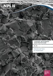
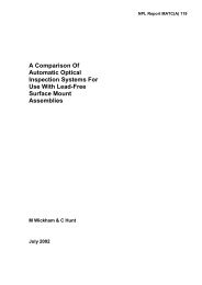
A NATIONAL MEASUREMENT<br />
GOOD PRACTICE GUIDE<br />
No. 110<br />
Reduce Copper Dissolution<br />
in Lead-Free Assembly
Measurement Good Practice Guide No. 110<br />
Good Practice Guide to Reduce Copper Dissolution<br />
in Lead-Free Assembly<br />
D. Di Maio, C. P. Hunt and B. Willis<br />
ABSTRACT<br />
During a successful soldering operation to a copper surface, a small amount of copper is<br />
dissolved to form a reliable interconnection and is perfectly normal. During the soldering<br />
operation, copper is dissolved by tin to form a tin/copper intermetallic and the amount<br />
dissolved is dependent on the soldering process, solder alloy, surfaces to be joined,<br />
temperature, time and solder flow rate. Using lead-free alloys requires higher soldering<br />
temperatures and potentially longer contact times, and hence the propensity for higher<br />
dissolution of copper.<br />
A typical intermetallic produced with a tin/lead solder can range between 1-3μm. In the case<br />
of lead-free soldering process this thickness can increase above 5μm. The intermetallics are<br />
themselves soluble in solder, and hence potentially the overall copper dissolution rate is<br />
greater. Dissolution during lead-free soldering does not just impact copper pads on printed<br />
boards, it can be a potential issue on thin copper wire, component terminations and hybrid<br />
metallisation. Examples of some typical problems previously experienced in industry are<br />
provided in this guide.<br />
1
© Crown copyright 2008<br />
Reproduced with the permission of the Controller of HMSO<br />
and the Queen's Printer for Scotland<br />
ISSN 1368-6550<br />
<strong>National</strong> <strong>Physical</strong> <strong>Laboratory</strong><br />
Hampton Road, Teddington, Middlesex, TW11 0LW<br />
Extracts from this report may be reproduced provided the source is acknowledged<br />
and the extract is not taken out of context.<br />
Approved on behalf of the Managing Director, <strong>NPL</strong><br />
by Dr M G Cain, Knowledge Leader,<br />
Industry and Innovation Division
Good Practice Guide 110<br />
Contents<br />
1 What is copper dissolution ? .............................................. 1<br />
1.1 What is copper dissolution ?......................................................................................2<br />
2 What is the impact to the user? ........................................... 4<br />
3 How can PCB specification help ? ........................................ 7<br />
4 Monitoring copper dissolution during fabrication and assembly ... 9<br />
4.1 Rework solder fountain............................................................................................11<br />
4.2 Selective soldering processes...................................................................................12<br />
4.3 Wave soldering ........................................................................................................12<br />
4.4 PCB solder levelling ................................................................................................13<br />
4.5 Manual soldering/de-soldering ................................................................................14<br />
4.6 Reflow soldering......................................................................................................14<br />
4.7 Copper dissolution, what do you look for?..............................................................15<br />
5 <strong>NPL</strong> on-Line Defect <strong>Database</strong> .............................................20<br />
6 Acknowledgements.........................................................23
Good Practice Guide 110<br />
1What is copper<br />
dissolution ?<br />
1<br />
IN THIS CHAPTER<br />
• Intermetallic formation in joints<br />
• Copper dissolution rate of lead-free alloy<br />
1
Good Practice Guide 110<br />
1.1 What is copper dissolution ?<br />
Copper dissolution is not a new phenomenon, it has always<br />
occurred when a soldering operation is conducted on a clean<br />
copper surface. If copper were not dissolved to some extent a<br />
reliable connection would not be produced. The dissolution<br />
process at the interface of the solder and copper forms an<br />
intermetallic, and this is the bond between the solder and copper.<br />
The intermetallic itself is soluble in solder, and hence the copper<br />
dissolution process is a two-stage process with the copper forming<br />
an intermetallic, and then the intermetallic dissolving in the solder.<br />
Factors that change the intermetallic composition and morphology,<br />
will be dependent on composition of the solder and copper, as well<br />
as copper microstructure, and probably the soldering process and<br />
the heat delivery and solder flow mechanisms. Hence copper<br />
dissolution is dependent on many factors. Figure 1 shows typical<br />
through hole solder joints with a component pin in the hole.<br />
(a)<br />
(b)<br />
20μm<br />
20μm<br />
Figure 1: Microsections of typical solder joints formed between a<br />
copper plated through hole and a through hole pin. (a)<br />
tin/lead joint after soldering, (b) lead-free<br />
Tin/Silver/Copper joint after soldering. The grey<br />
boundary layers on both solders are intermetallic alloys,<br />
and the particles in the lead-free solder are also<br />
intermetallics.<br />
Copper dissolution, when discussed in a lead-free context, refers to<br />
excessive copper loss; 10μm and above would be considered<br />
excessive hence the concern shown by industry. In Figure 2 the<br />
results of an experiment with copper wire show the different<br />
dissolution rates in three eutectic solders. This data clearly<br />
confirms the relative increase seen in dissolution with these simple<br />
lead-free alloys. Current commercial alloys are capable of<br />
achieving lower dissolution rates than seen in Figure 2, achieving<br />
rates as good as or better than SnPb, see <strong>NPL</strong> Report MAT26:<br />
2
<strong>NPL</strong> Good Practice Guide 110<br />
Measurements of Copper Dissolution in Lead-Free Solder Alloys.<br />
Improvements in resistance to copper dissolution have been<br />
achieved by alloying small fractions of key elements, the most<br />
notable of which is Ni, but Co has also been used and there are<br />
examples of others. The mechanism for this improvement is still<br />
the subject of research. Exposing a copper surface to such a<br />
modified alloy with these additions is hypothesised to stabilise the<br />
intermetallic. Hence a PCB finished in a HASL process with an<br />
alloy with a Ni addition can reduce copper erosion in subsequent<br />
processing irrespective of the solder alloy used subsequently.<br />
Figure 2: Dissolution rate of copper wires immersed in SnAg,<br />
SnCu and SnPb solder fountain at 275°C<br />
Copper dissolution into the solder will also depend on the<br />
solubility of copper in the solder, and this will change as more<br />
copper dissolves into the solder. Hence as the number of boards<br />
processed increases, so will the copper dissolving into the solder<br />
decrease as the solubility limit is reached.<br />
3<br />
3
Good Practice Guide 110<br />
2What is the impact<br />
to the user?<br />
2<br />
IN THIS CHAPTER<br />
• Copper loss during production<br />
• Dissolution of component terminations<br />
4
Good Practice Guide 110<br />
2 What is the impact to the user?<br />
Excessive copper dissolution can lead to intermittent or lack of electrical interconnection on<br />
copper tracks or through hole plating; in severe cases this will reduce reliability. To date most<br />
cases experienced in industry have been when excessive loss has occurred and is very<br />
obvious during inspection; however, other less obvious cases may have undoubtedly occurred<br />
and have not been noted.<br />
Figure 3: Examples of dissolution could be the failure of track connections to plated<br />
through holes or simply the loss of the copper pad. The printed board surface<br />
finish in this case was silver.<br />
Figure 4:<br />
Loss of through hole connections where the knee/pad of the plated hole has been<br />
dissolved during selective soldering with a lead-free alloy. The surface pad finish<br />
on this board was copper Organic Solderable Preservative OSP.<br />
5
Good Practice Guide 110<br />
Figure 5:<br />
Reduction of cross-sectional area of thin copper wires. After changing from<br />
tin/lead to lead-free soldering dip soldering there was a noticeable reduction in<br />
the wire thickness<br />
Figure 6: A related issue is the loss of chip component plating that could lead to<br />
intermittent joints. During soldering the chip capacitor metallisation has been<br />
leached from the surface of the ceramic. To avoid ensure the correct specification<br />
of the components.<br />
6
<strong>NPL</strong> Good Practice Guide 110<br />
3How can PCB<br />
specification help ?<br />
3<br />
IN THIS CHAPTER<br />
• Copper plating thickness control<br />
• Updating specifications<br />
7
Good Practice Guide 110<br />
3 How can PCB specification help?<br />
Printed board specifications exist in the industry to cover the plated copper and original<br />
copper foil thickness for plated through hole and single sided boards. Documents from the<br />
IEC and IPC are available and are often supplemented by customer specific documents.<br />
Generally copper dissolution with lead-free alloy has not been addressed.<br />
Currently minimum copper thickness in a plated through hole is 20μm, 18μm in a small via<br />
or blind via hole. Surface tracking or plated through holes would be most affected by the<br />
soldering process, via holes in standard assembly are less likely to be affected.<br />
It is good practice to independently check the copper thickness on the PCB, using<br />
microsectioning for example. Microstructure can be important and this can be checked with a<br />
suitable etched section.<br />
If the minimum copper thickness specified is to be increased then it needs to be discussed and<br />
agreed with the supplier. Industry experience suggests that copper thickness is not the only<br />
circuit board related issue, and engineers need to discuss the type of copper utilised if<br />
different suppliers are being used to supply printed circuit boards.<br />
Copper dissolution will vary with different solder finishes like lead-free solder levelling, tin,<br />
silver and copper Organic Solder Preservative (OSP). In the case of nickel gold boards,<br />
copper dissolution should not be experienced, since during soldering, the joint is formed<br />
between the solder and the nickel layer, and not the copper. Nickel has a much slower<br />
dissolution rate in solder when compared to copper.<br />
Copper can be found in at least three different forms on the PCB, electroplated, reverse plated<br />
and electrodeposited. These copper types have different dissolution rates. The work at <strong>NPL</strong><br />
shows that electroplated copper suffers the highest dissolution rate, followed by reverse<br />
treated copper. Electrodeposited copper has the lowest dissolution rate.<br />
Solder levelled boards using a lead-free alloy will have already experienced some copper loss<br />
during the levelling operation. The process, materials and any potential rework of panels<br />
during PCB manufacture should be discussed with the supplier.<br />
8
<strong>NPL</strong> Good Practice Guide 110<br />
4Monitoring copper<br />
dissolution during<br />
fabrication and<br />
assembly<br />
4<br />
IN THIS CHAPTER<br />
• Impact of assembly process<br />
• Alloy, temperature and process flow rate<br />
9
Good Practice Guide 110<br />
4 Monitoring copper dissolution during fabrication<br />
and assembly<br />
All soldering processes can potentially reduce the amount of copper on the surface of the board or<br />
in the plated through holes. In such areas of thin copper the effects of dissolution will be worse.<br />
Copper dissolution rates are affected by the following (see Figure 7):<br />
Solder alloy used<br />
Soldering temperature and time<br />
Solder flow rate across copper surfaces<br />
Copper type and surface coating<br />
Figure 7<br />
Main variables affecting the dissolution of copper in soldering processes.<br />
Based on standard assembly and fabrication processes conducted with lead-free alloys and the<br />
typical parameters used in industry, the processes discussed below are most likely to have the<br />
greatest impact on copper dissolution rates.<br />
As a general guide every attempt should be made to reduce the soldering temperature and soldering<br />
time. It is more difficult to reduce the soldering flow rate in processes like rework, selective<br />
soldering, levelling and wave soldering, as this is a fundamental part of the process to improve<br />
drainage and reduce short circuits. Every effort should be made to optimise pre-heating for each of<br />
these processes rather than use the solder energy as part of the pre-heating process, and hence<br />
reduce the solder contact time. Thermal profiling is recommended to optimise these soldering<br />
processes.<br />
The most common assembly process steps are listed in order of potential copper dissolution rate,<br />
each process requires close monitoring during production. The first four processes normally have a<br />
significant volume of solder that moves quickly across exposed copper surfaces:<br />
10
<strong>NPL</strong> Good Practice Guide 110<br />
• Rework Solder Fountains<br />
• Selective Soldering Processes<br />
• Wave soldering<br />
• PCB Solder levelling<br />
• Manual soldering/de-soldering<br />
• Reflow soldering<br />
4.1 Rework solder fountain<br />
Figure 8<br />
Typical solder fountain equipment. (Example image kindly provided by ZEVAC)<br />
Solder fountains are used for reworking large through hole multi-pin components like connectors<br />
and sockets. A solder fountain is used so that all through hole terminations can be reflowed<br />
simultaneously, when the printed board and connector terminations are held in contact with the<br />
molten solder. When all solder joints are in a liquid state, the component can be removed from the<br />
printed board. This process is used as an alternative to a vacuum de-soldering iron, which desolders<br />
each pin individually.<br />
When a solder fountain is used, the plated through holes will still be blocked after removing the<br />
component terminations. The solder must be blown out of the holes when still in a liquid state or the<br />
board must be subjected to a second de-soldering operation. Most solder fountains used for rework<br />
do not have pre-heat. This will extend the solder contact times on thermally challenging boards.<br />
Some waves are pumped with a near static flow, some have faster flowing waves to increase heat<br />
transfer and maintain better control of the solder bath temperature. Generally the faster the flow-rate<br />
the higher the copper dissolution. The design of the nozzle and distribution of pressure across the<br />
ducting will also impact copper removal rates.<br />
11
Good Practice Guide 110<br />
4.2 Selective soldering processes<br />
Figure 9<br />
A fixed nozzle selective soldering machine<br />
There are two types of selective soldering systems, a fixed nozzle where the board<br />
assembly/connections move through the flowing solder, or systems with a dedicated series of solder<br />
nozzles. The first type is the most popular for both small and medium volume users, and the second<br />
type are used in high volume dedicated equipment. The board assembly is lowered into contact with<br />
the solder, simultaneously soldering multiple connectors in one step. Prior to soldering, selected<br />
areas are fluxed and the board is pre-heated. On some systems, there is no pre-heat or the profiling<br />
of the board is not done correctly. This leads to the use of longer soldering times or engineers<br />
increasing solder temperature and contact time, both resulting in increased copper dissolution rates.<br />
4.3 Wave soldering<br />
Figure 10 Wave soldering machine<br />
Most wave soldering systems use a lambda shape wave, where the solder flows in the opposite<br />
direction to the board travel. When the board assembly contacts the wave, the solder also starts to<br />
12
<strong>NPL</strong> Good Practice Guide 110<br />
flow in both directions. Typically during wave soldering the board assembly is pre heated to 100-<br />
120°C measured on the topside of the board, the base of the board may be 20-30°C higher.<br />
With the introduction of lead-free soldering typical conveyor speeds have decreased, increasing the<br />
solder contact times with all copper surfaces. Some suppliers have modified the design of the wave<br />
ducting to increase the potential contact time, thus avoiding a reduction in conveyor speed. The<br />
dissolution rate in wave soldering will therefore be associated with the wave temperature, conveyor<br />
speed and contact time.<br />
4.4 PCB solder levelling<br />
Figure 11: Application of lead-free solderable finish with a vertical solder levelling system<br />
With the exception of electroless nickel immersion gold (ENIG), all board finishes like silver, tin,<br />
copper OSP and solder levelled board will experience some level of copper dissolution during<br />
assembly. The nickel in the ENIG finish has a much slower dissolution rate compared to copper and<br />
normally the 2-4um of nickel under the gold will not be removed. Typically any solder levelling<br />
process will remove copper during application of a fresh coating of either tin/lead or lead-free<br />
solder. There may be more evidence of copper removal on a vertical levelling process as the bottom<br />
of the process panel will be in contact with the solder for a longer period of time than the top. On a<br />
horizontal system contact times will be the same across a panel, similar to the wave solder process.<br />
Solder temperature, dwell time, solder alloy, copper previously absorbed and flow rate will affect<br />
the amount of copper removed in a single pass.<br />
In the early days of lead-free, it was common practice to double dip panels due to inadequate heat<br />
input or the performance of the flux. The use of this process was an attempt to improve the surface<br />
coverage and visual appearance, but can result in further copper removal. Today a double dip may<br />
be conducted for thermally demanding boards, however the total process time may be less than a<br />
single pass.<br />
During solder levelling it is good practice to monitor the copper dissolution rates, the alloy<br />
contamination levels, alloy being used; users should make sure that this is being conducted during<br />
PCB evaluation or supplier audit.<br />
13
Good Practice Guide 110<br />
4.5 Manual soldering/de-soldering<br />
Figure 12 Soldering with a tip can cause copper dissolution<br />
Manual soldering and de-soldering will dissolve copper from the exposed pad and through hole<br />
plating. The copper is dissolved as the solder flows across the surface of the copper during<br />
soldering, further copper can be removed when the solder is removed from the surface.<br />
During manual soldering it is not common industry practice to pre-heat boards for either soldering<br />
or de-soldering, hence the soldering temperatures are higher and soldering times are longer than<br />
with other processes. Often manual soldering/de-soldering is used in rework after mass soldering<br />
and adds to any dissolution that has already occurred.<br />
4.6 Reflow soldering<br />
Figure 13 Typical reflow solder joint<br />
Reflowing solder paste on pads for surface mount terminations or inside plated through holes for<br />
intrusive reflow of conventional leads, will dissolve copper as with any soldering process. The<br />
solder alloy, surface finish and temperature are the main factors affecting copper dissolution rates.<br />
14
<strong>NPL</strong> Good Practice Guide 110<br />
During reflow the flow rate of solder across the surface is minimal. Experience with lead-free<br />
solders already shows that wetting and flow are limited and less than with tin/lead solders. A typical<br />
surface mount joint experiencing one reflow cycle, may have a tin/copper intermetallic of 2-3μm,<br />
and intrusive reflow joint in a through hole termination, may have 3-5μm.<br />
There is little experience of significant copper dissolution on reflow soldering. Copper intermetallic<br />
formation will vary based on soldering temperatures, time in a liquid state and the cooling time<br />
above liquidus. Reflow and multiple rework operations of joints may have a cumulative effect.<br />
4.7 Copper dissolution, what do you look for?<br />
The photographic examples are provided for reference to aid engineers and production staff to<br />
identify evidence of copper dissolution. Copper dissolution to the degree shown on the examples<br />
would be considered extreme but are being experienced in manufacture. Evidence of printed board<br />
assemblies featuring similar examples should be investigated urgently and the production process or<br />
materials reviewed.<br />
Figure 14 Solder pad dissolution leading to pad loss after selective soldering (in area indicated)<br />
15
Good Practice Guide 110<br />
Figure 15 Solder dissolution of copper, has left limited copper pad and knee of the plated through<br />
hole after selective soldering on printed board with a silver finish<br />
Figure 16 Microsection views of copper pad and knee area of a plated through hole showing<br />
evidence of dissolution<br />
16
<strong>NPL</strong> Good Practice Guide 110<br />
Figure 17 Thin copper wire reduction by lead-free solder<br />
Figure 18 Copper dissolution on soldering iron tip. The copper core has been dissolved by leadfree<br />
solder after damage to tip outer plating<br />
17
Good Practice Guide 110<br />
Figure 19: Related defect of dissolution of chip capacitor terminations referred to as leaching. The<br />
contact has been dissolved during soldering due to lack of a nickel barrier layer on the<br />
terminations<br />
Figure 20: Copper dissolution of copper barrier layer on steel pin. Lack of a barrier layer on the<br />
base material has prevented a true bond forming on the surface of the steel surface.<br />
Copper or nickel barrier layers are often used to provide ease of soldering<br />
18
<strong>NPL</strong> Good Practice Guide 110<br />
Figure 21: Hybrid circuit pad dissolution due to extended soldering times, the chip resistor shows<br />
satisfactory wetting with all the solder wicking up the resistor termination<br />
Further information on copper dissolution is available from <strong>NPL</strong> in the form of a report on project<br />
work: <strong>NPL</strong> Report MAT26: Measurements of Copper Dissolution in Lead-Free Solder Alloys.<br />
19
Good Practice Guide 110<br />
5<strong>NPL</strong> on-Line Defect<br />
<strong>Database</strong><br />
5<br />
IN THIS CHAPTER<br />
• Solving production problems 24/7<br />
• Defect types and solutions available online<br />
20
Good Practice Guide 110<br />
5 <strong>NPL</strong> On-Line Defect <strong>Database</strong><br />
Excessive copper dissolution is just one of the new process issues experienced by industry and it is<br />
hoped that this best practice guide will go some way to assisting engineers reduce the possibility of<br />
excessive copper loss during manufacture. To further assist the continued introduction and<br />
improvement projects in lead-free, <strong>NPL</strong> have produced a free online resource.<br />
With support from our industry partners, an interactive assembly and soldering defect database has<br />
been created, allowing engineers to search through a range of defects covering components, printed<br />
circuit boards and assembly problems. The aim is to add more process, material and environmental<br />
defects through online submissions by industry worldwide at http://defectsdatabase.npl.co.uk/<br />
The interactive database will help engineers solve their problems and obtain practical advice day or<br />
night. A very practical benefit is its on-line global availability 24/7 to shop floor operators as a<br />
reference and training resource.<br />
Figure 22 Screen shot showing the front page of the <strong>NPL</strong> Defect <strong>Database</strong><br />
The screen shot shows the front page of the <strong>NPL</strong> Defect <strong>Database</strong> where engineers can query the<br />
database for soldering defects, assembly process, alloy type, production or field failure etc.<br />
Alternatively if the defect is not available then it’s easy to submit a photograph for inclusion in the<br />
online database with feedback on defect causes and possible solutions.<br />
21
Good Practice Guide 110<br />
Figure 23 Screen shots shows an example of one soldering defect<br />
The screen shots shows an example of one soldering defect found after a search of the database<br />
providing information on the defect, how it could have occurred and possible solutions. Selecting the<br />
defect image can provide a larger view of the defect, a second image, and the opportunity to print out<br />
the defect for shop floor staff reference or discussion with other departments or suppliers.<br />
The <strong>NPL</strong> Defects <strong>Database</strong> is available to allow engineers to search for solutions to common<br />
problems or submit defects online with full details or requesting advice and a possible solution to the<br />
process issues or failures at http://defectsdatabase.npl.co.uk/<br />
We would like to thank all our partners on the Copper Dissolution Studio project and the<br />
contributions to this best practice guide and the final report. Further details on the project and the<br />
final report can be obtained by contacting Ling Zou (email ling.zou@npl.co.UK, telephone 0208<br />
943 6065.<br />
22
Good Practice Guide 110<br />
6Acknowledgements<br />
We would like to thank the Department for Innovation, Universities and Skills (DIUS) for funding<br />
contributions to this research. We would also like to acknowledge Milos Dusek for his help in<br />
setting up some of the experiments.<br />
We would also like to acknowledge the support and funding of the following project partners<br />
(included in alphabetical order):<br />
Artetch Circuits<br />
Celestica<br />
Cookson Electronic Assembly<br />
DKL Metals<br />
Dolby Laboratories<br />
European Sapce Agency<br />
Falcon Metals<br />
Henkel Technologies<br />
Hewlett-Packard Co<br />
Indium Corporation of Europe<br />
MBDA (UK)<br />
Photomechanical Services (Essex) Ltd<br />
Rockwell Collins<br />
Seho<br />
Vitronics Soltec BV<br />
23