COOLFLOW™ IRRIGATION PUMP USER ... - Biosense Webster
COOLFLOW™ IRRIGATION PUMP USER ... - Biosense Webster
COOLFLOW™ IRRIGATION PUMP USER ... - Biosense Webster

You also want an ePaper? Increase the reach of your titles
YUMPU automatically turns print PDFs into web optimized ePapers that Google loves.
COOLFLOW <strong>IRRIGATION</strong> <strong>PUMP</strong><br />
<strong>USER</strong> MANUAL<br />
Manual P/N: M-5276-323A
© 2001 <strong>Biosense</strong> <strong>Webster</strong>, Inc.<br />
All rights reserved.<br />
<strong>Biosense</strong> <strong>Webster</strong>, Inc.<br />
3333 Diamond Canyon Road<br />
Diamond Bar, CA 91765, USA<br />
Tel: +1-909-839-8500<br />
Tel: +1-800-729-9010<br />
Fax: +1-909-468-2905<br />
www.biosensewebster.com<br />
<strong>Biosense</strong> <strong>Webster</strong><br />
Johnson & Johnson Medical NV/SA<br />
Dreve Richelle 161 Building H<br />
B-1410 Waterloo, Belgium<br />
Tel: +32-2-352-1411<br />
Fax: +32-2-352-1592<br />
<strong>Biosense</strong> <strong>Webster</strong> (Israel), Ltd.<br />
Einstein Building<br />
7 Etgar Street<br />
P.O. Box 2009<br />
Tirat-Ha Carmel 39120, Israel<br />
Tel: +972-4-857-6057<br />
Fax: +972-4-857-1071<br />
COOLFLOW is a trademark of <strong>Biosense</strong> <strong>Webster</strong>, Inc.<br />
Caution: Federal (U.S.A.) law restricts this device to sale by or on the order of a physician.<br />
Manual P/N: M-5276-323A
TABLE OF CONTENTS<br />
COOLFLOW Irrigation Pump<br />
User Manual – English<br />
User Manual – English 1-1<br />
1. Device Description ______________________________________ 1-3<br />
Unpacking the Pump.........................................................................1-3<br />
Electrical Connections ......................................................................1-4<br />
2. Safety Information _______________________________________ 1-4<br />
Intended Use / Indications ................................................................1-4<br />
Warnings...........................................................................................1-4<br />
Precautions.......................................................................................1-5<br />
3. Setting Up the COOLFLOW Pump ___________________________ 1-6<br />
IV Pole Mount ...................................................................................1-6<br />
Turning the Pump On........................................................................1-7<br />
Loading the Tubing Set in the Pump.................................................1-7<br />
Preparing for Irrigation ......................................................................1-9<br />
4. Working with the Control Panel ____________________________ 1-9<br />
5. Using the Foot Pedal (optional) ___________________________ 1-11<br />
6. Alarms and Error Codes _________________________________ 1-11<br />
7. Preventive Maintenance / Service _________________________ 1-13<br />
Cleaning..........................................................................................1-13<br />
Preventive Maintenance .................................................................1-13<br />
Calibration/Adjustments ..................................................................1-13<br />
Storage ...........................................................................................1-13<br />
8. Specifications _________________________________________ 1-14<br />
EMC Information.............................................................................1-15<br />
9. Accessories ___________________________________________ 1-19<br />
10. Limited Warranty & Limitation of Liability___________________ 1-20<br />
COOLFLOW Irrigation Pump
1-2 User Manual – English<br />
LIST OF FIGURES & TABLES<br />
COOLFLOW Irrigation Pump<br />
Figure 1: The COOLFLOW Irrigation Pump. .............................................1-3<br />
Figure 2: Front view of the COOLFLOW Pump. .......................................1-6<br />
Figure 3: Rear view of the COOLFLOW Pump..........................................1-7<br />
Figure 4: Loading the tubing set in the pump. ......................................1-8<br />
Figure 5: Close-up of the COOLFLOW pump control panel....................1-9<br />
Figure 6: The optional Foot Pedal used with the COOLFLOW<br />
Pump. ......................................................................................1-11<br />
Table 1: Alarms and Error Codes, and the appropriate action.........1-12<br />
Table 2: Electromagnetic emissions ..................................................1-15<br />
Table 3: Electromagnetic immunity ....................................................1-16<br />
Table 4: Electromagnetic immunity ....................................................1-17<br />
Table 5: Recommended separation distances between portable<br />
and mobile RF communications equipment and the<br />
COOLFLOW Irrigation Pump ...................................................1-18
1. DEVICE DESCRIPTION<br />
User Manual – English 1-3<br />
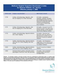
The COOLFLOW Irrigation Pump is a peristaltic pump designed for the delivery of<br />
irrigation solutions when used in conjunction with the COOLFLOW Tubing Set and a<br />
ThermoCool ® Catheter. The pump has a dual rate feature for one-touch irrigation<br />
rate change between a low flow rate (1-5 ml/min) and a high flow rate (5-30 ml/min).<br />
A large LED display indicates the flow rate selected. An optional foot pedal can be<br />
used to initiate high flow irrigation.<br />
Figure 1:<br />
The COOLFLOW<br />
Irrigation Pump.<br />
A transparent door protects the rotating head, while allowing visibility of the entire<br />
tubing set during pump operation.<br />
Dual air-in-line detectors are employed for added safety in preventing air infusion.<br />
Audible alarms warn of air in the tubing, an open door, or operational errors.<br />
A removable side-mounted pole clamp is included for mounting the pump to an IV<br />
pole or a horizontal mounting rail.<br />
Unpacking the Pump<br />
Remove the pump and power cord from the shipping container. Inspect the pump.<br />
If the pump has been damaged during shipping, please contact your nearest <strong>Biosense</strong><br />
<strong>Webster</strong> Sales or Customer Service representative.<br />
COOLFLOW Irrigation Pump
1-4 User Manual – English<br />
Electrical Connections<br />
COOLFLOW Irrigation Pump<br />
The pump operates using line power of 100 to 240V~, 50 to 60Hz. Connect only to a<br />
properly grounded 3-wire hospital grade power receptacle. The pump is not battery<br />
powered and cannot be used as portable equipment.<br />
2. SAFETY INFORMATION<br />
Intended Use / Indications<br />
Warnings<br />
The COOLFLOW Irrigation Pump and Tubing Set is a peristaltic irrigation pump<br />
designed for the delivery of saline solution when used in conjunction with the<br />
Stockert 70 RF Generator and the ThermoCool Irrigation Catheter.<br />
• The COOLFLOW Pump is designed for use with only the <strong>Biosense</strong> <strong>Webster</strong><br />
COOLFLOW Tubing Set only. Use of inappropriate tubing may cause improper<br />
operation of the pump and can result in improper irrigation.<br />
• The COOLFLOW Pump is designed to stop the flow of irrigation solution when an<br />
alarm is activated. All alarms must be attended to immediately to ensure<br />
continued irrigation.<br />
• The COOLFLOW Pump is designed for use with the ThermoCool catheter and the<br />
Stockert 70 Generator, which can detect hazard conditions caused by insufficient<br />
irrigation flow to the catheter tip. Flow can be verified visually by noting the drip<br />
rate in the drip chamber. Hospital personnel are responsible for verifying and<br />
monitoring the flow rate delivered to prevent under-infusion of irrigation fluid.<br />
• Hospital personnel are responsible for monitoring the total saline load delivered<br />
to the patient to prevent over-infusion of irrigation fluid.<br />
• Hospital personnel are responsible for verifying the proper performance of the<br />
pump and the compatibility of the solutions and irrigation devices used as part of<br />
the overall irrigation management. The COOLFLOW Pump and Tubing Set are designed<br />
for use with standard irrigation solutions such as normal saline. Specified<br />
flow rate accuracy may not be maintained when used with incompatible fluids or<br />
delivery devices.<br />
• The COOLFLOW Irrigation Pump should not be used adjacent to or stacked with<br />
other equipment. If adjacent or stacked use is necessary, observe the COOLFLOW<br />
Irrigation Pump to verify normal operation in the configuration in which it will<br />
be used.
Precautions<br />
User Manual – English 1-5<br />
• To avoid the possibility of biological contamination, and to ensure proper<br />
performance, do not reuse or resterilize the COOLFLOW Tubing Set. The tubing<br />
set is intended for single use only.<br />
• Positive displacement irrigation pumps such as the COOLFLOW Pump should not<br />
be ported together with other infusion systems, including gravity fed IV infusion<br />
systems.<br />
• To avoid the risk of explosion, do not use the pump in the presence of flammable<br />
anesthetics.<br />
• To avoid the risk of electrical shock and fire, do not expose the pump to<br />
excessive moisture.<br />
• External high-energy radio frequency interference (RFI) and electromagnetic<br />
radiation (EMR) can cause false alarms or compromised performance in<br />
electrical equipment such as the COOLFLOW Pump. In addition, electrical<br />
equipment such as the pump can occasionally induce artifacts on ECG monitoring<br />
systems that are not operating under optimal conditions. Although the pump<br />
has been designed to prevent such interference, safe operation should be verified<br />
prior to patient use when used in conjunction with RF electro-surgical equipment,<br />
electromagnetic navigation systems and ECG monitoring equipment. If<br />
interference occurs, reposition the pump.<br />
• The pump has no user-serviceable components.<br />
• The pump is calibrated by the manufacturer. Alteration of pump settings will<br />
cause improper operation and result in cancellation of the warranty.<br />
• Moving parts such as the transparent door, pole clamp and rotating pump head,<br />
while designed for safe operation, should be operated with care.<br />
COOLFLOW Irrigation Pump
1-6 User Manual – English<br />
3. SETTING UP THE COOLFLOW <strong>PUMP</strong><br />
IV Pole Mount<br />
COOLFLOW Irrigation Pump<br />
Figures 2 and 3 provide front and rear view details of the COOLFLOW Pump,<br />
respectively.<br />
The pump can be mounted on a standard IV pole or a horizontal mounting rail using<br />
the removable pole clamp (#1 in Figure 2).<br />
To install the pole mount:<br />
1. Securely clamp the pole clamp onto the IV pole or mounting rail near the<br />
patient.<br />
2. Slide the mounting post into the pole clamp. Make sure that the pole is stable<br />
prior to use.<br />
� NOTES • It is recommended that a 5-legged hospital grade IV pole be used.<br />
• To ensure stability, the pump should not be mounted higher than<br />
135 cm above the base of the pole.<br />
Figure 2:<br />
Front view of the<br />
COOLFLOW Pump.<br />
1) Pole clamp<br />
2) Door latch<br />
3) Pump Head<br />
4) Control Panel<br />
5) LED display
Turning the Pump On<br />
User Manual – English 1-7<br />
The power switch (# 7 in Figure 3) is located on the back panel near the power cord<br />
inlet.<br />
Once turned on, the pump performs a self-test and you will hear a short beeping tone.<br />
Once the self-test has passed, you will hear the tone again and the display will<br />
indicate a flow rate of 0 ml/min.<br />
Figure 3:<br />
Rear view of the<br />
COOLFLOW Pump.<br />
6) AC power inlet<br />
7) Power switch<br />
8) Foot pedal<br />
connector<br />
9) Alternate foot pedal<br />
connector<br />
10) Ground Stud<br />
Loading the Tubing Set in the Pump<br />
� NOTE<br />
Use only the <strong>Biosense</strong> <strong>Webster</strong> COOLFLOW Tubing Set.<br />
To load the COOLFLOW Tubing Set in the pump (refer to Figure 4):<br />
1. Connect the COOLFLOW Tubing Set to the IV solution container using standard<br />
safe hospital practices.<br />
• A new tubing set must be used for every procedure.<br />
Do not reuse the tubing set.<br />
2. Connect a stopcock to the patient end of the tubing set.<br />
COOLFLOW Irrigation Pump
1-8 User Manual – English<br />
COOLFLOW Irrigation Pump<br />
3. Open the stopcock and fill the tubing set with irrigation fluid. Remove any<br />
trapped air and then close the stopcock.<br />
Figure 4:<br />
Loading the tubing set<br />
in the pump.<br />
See text for details.<br />
4. Hang the IV solution container near the pump, and fill the drip chamber about<br />
2/3 full.<br />
5. Open the door of the pump and release the spring arm (11) from the pressure<br />
plate (12).<br />
6. Install the Large Tubing Stop (13) of the tubing set into the Lower Tubing<br />
Retainer (14). Note: the pump rotates in a clockwise direction.<br />
7. Lay the tubing over the rollers on the left side of the pump head (15).<br />
8. Gently stretch the tubing and place the Small Tubing Stop (16) of the tubing set<br />
into the Upper Tubing Retainer (17). Do not twist the tubing.<br />
9. Place the smaller diameter tubing sections (18) fully into each Air-In-Line<br />
Detector (19).<br />
• To ensure proper operation of the Air-In-Line Detectors, the outer surface of<br />
the tubing must be dry.<br />
10. Close the pressure plate and latch the spring arm.<br />
• Closing the pressure plate prevents free flow of fluids though the tubing set.<br />
11. Close the transparent door of the pump.
Preparing for Irrigation<br />
To prepare for irrigation:<br />
User Manual – English 1-9<br />
1. Open the stopcock on the end of the tubing set.<br />
2. Press and hold the Flush button ( ) to verify tubing integrity.<br />
• If you see any air in the tubing, hold down on the Flush button until the air<br />
is expelled through the open end of the tubing.<br />
3. Securely connect the tubing to the ThermoCool Catheter.<br />
The COOLFLOW Irrigation Pump is now ready for use.<br />
4. WORKING WITH THE CONTROL PANEL<br />
The control panel, located on the front of the pump, is used to set and display the<br />
flow rate, and to control pump operation. A close-up of the control panel is shown in<br />
Figure 5.<br />
Figure 5:<br />
Close-up of the<br />
COOLFLOW pump<br />
control panel.<br />
Use of the controls is detailed below.<br />
Stop button: Press to Stop rotation of the pump head. The pump will<br />
beep once to indicate that flow has stopped.<br />
Press the Low Flow or High Flow button to restart the flow.<br />
Flush button: Press to flush the tubing set. A flow of 60 ml/min is<br />
initiated and continues until the button is released. Detection of air in<br />
the tubing is disabled during this process.<br />
Low Flow button: Press to initiate flow at the preset low flow rate.<br />
The pump beeps once when the low flow rate begins. The default low<br />
flow rate is 2 ml/min.<br />
COOLFLOW Irrigation Pump
1-10 User Manual – English<br />
COOLFLOW Irrigation Pump<br />
High Flow button: Press to initiate flow at the preset high flow rate.<br />
The pump beeps twice when the high flow rate begins. The default<br />
high flow rate is 30 ml/min.<br />
Increase (+)/Decrease (-) buttons: There are two sets of<br />
Increase/Decrease buttons, one set under the Low Flow button, the<br />
other under the High Flow button. Press the “+” or “-” button to<br />
increase or decrease the respective flow rate by 1 ml/min.<br />
When adjusting the high or low flow rate, the LED display<br />
temporarily indicates the new setting for the associated flow rate,<br />
regardless of the current flow rate of the pump.<br />
The new setting remains in effect until it is changed, or the pump is<br />
turned off.<br />
Alarm Silence button: When an error is detected by the pump, the<br />
error code appears on the LED display and an audible alarm is heard.<br />
Press this button to silence the audible alarm for 2 minutes. The error<br />
code remains displayed until the Clear Error button is pressed (see<br />
below).<br />
Clear Error button: Once an error has been corrected, press and<br />
hold the CLR button for 1 second to clear the error from the display.<br />
The pump returns to normal operating mode.<br />
LED Display: The two-digit seven-segment LED display indicates<br />
the flow rate of the pump in ml/min. The actual flow rate is dependent<br />
on the tubing set integrity and fluid back pressure. When the pump is<br />
stopped, 0 ml/min is indicated.<br />
When an error is detected the error code is displayed until that error<br />
has been cleared. Once the error is corrected (see Section 6: Alarms<br />
and Error Codes), use the Clear Error button (see above) to return to<br />
normal operation.<br />
When adjusting the flow rate, the new setting for the associated flow<br />
rate is briefly displayed, regardless of the current flow rate of the<br />
pump.<br />
For example: If the pump is currently running at a low flow rate of<br />
2 ml/min and the high flow rate setting is changed, the new high flow<br />
rate setting is momentarily displayed.
5. USING THE FOOT PEDAL (OPTIONAL)<br />
The foot pedal may be used to momentarily initiate a high flow rate.<br />
To connect the foot pedal to the pump:<br />
User Manual – English 1-11<br />
1. Place the Redel connector of the COOLFLOW Pedal (Figure 6) in the socket at<br />
the back of the pump (#8 in Figure 3).<br />
• The foot pedal is ready for use immediately upon connection.<br />
2. An additional foot pedal connector (#9 - ‘D’ shaped 9-pin) is also provided on<br />
the back panel. For further details about this feature, contact your <strong>Biosense</strong><br />
<strong>Webster</strong> representative, or refer to the COOLFLOW Irrigation Pump Service<br />
Manual, available from <strong>Biosense</strong> <strong>Webster</strong>.<br />
To initiate the high flow rate with the pedal set:<br />
1. Check that the pump is stopped, or running at a low flow rate.<br />
2. Press and hold on the foot pedal.<br />
• You will hear two beeps indicating initiation of the high flow rate.<br />
• High flow is maintained while the pedal is held down.<br />
3. To stop the high flow rate, release the foot pedal.<br />
• You will hear one beep indicating a return to the low flow rate.<br />
Figure 6:<br />
The optional Foot<br />
Pedal used with the<br />
COOLFLOW Pump.<br />
6. ALARMS AND ERROR CODES<br />
When an error occurs or an alarm is activated, an audible warning is heard. The<br />
associated error/alarm code is shown in the LED display and the pump is stopped<br />
(exception: see “Air Bubble Detected” below).<br />
The audible alarm can be temporarily silenced by pressing the “Alarm Silence”<br />
button. The code remains displayed and the audible alarm returns after 2 minutes.<br />
To clear an alarm or error, press and hold the “CLR” button for 1 second. The pump<br />
will remain stopped and return to the normal operating mode.<br />
A list of alarm and error codes, with the appropriate course of action is provided in<br />
Table 1.<br />
COOLFLOW Irrigation Pump
1-12 User Manual – English<br />
bF<br />
COOLFLOW Irrigation Pump<br />
Table 1: Alarms and Error Codes, and the appropriate action.<br />
Codes are listed in alphabetical order.<br />
Code Alarm/Error Type Action<br />
Blinking<br />
Flow Rate<br />
(in LED<br />
display)<br />
bu<br />
Ch<br />
do<br />
Fo<br />
Pr<br />
r1<br />
r2<br />
Bubble Detector Self Test Failure:<br />
Periodic self test of the air-in-line<br />
sensors has failed.<br />
High Flow Rate Time Reminder:<br />
The pump has been operating at a<br />
high flow rate for more than 6<br />
minutes.<br />
Air Bubble Detected: Air was<br />
detected in the tubing by one of the<br />
air-in-line sensors. The pump will<br />
continue to rotate for 3 seconds<br />
before stopping, to briefly ensure<br />
continued irrigation while any<br />
associated equipment is turned off or<br />
removed from the patient.<br />
Self Test: A hardware self-test is in<br />
progress.<br />
Door Open: The door is open during<br />
pump operation.<br />
Foot Pedal: Communication with the<br />
Foot Pedal has been lost during high<br />
flow operation.<br />
Internal Processor Error: An<br />
internal error has been detected in<br />
the micro controller or one of its<br />
supporting components.<br />
Rotation Velocity Error: The pump<br />
head rotation speed was not as<br />
expected.<br />
Reverse Rotation Error: Reverse<br />
pump head rotation was briefly<br />
detected.<br />
� Turn power off and on again.<br />
� If the failure occurs repeatedly,<br />
contact your local <strong>Biosense</strong> <strong>Webster</strong><br />
Sales or Customer Service<br />
representative.<br />
� Press the Silence Alarm button to stop<br />
the audible alarm for 2 minutes.<br />
Or<br />
� Switch to the low flow rate.<br />
� Examine the tubing for trapped air.<br />
� Remove the patient line from the<br />
patient and use the Flush button to<br />
purge air from the system.<br />
� Check that the tubing is properly<br />
seated in the Air-in-Line detectors.<br />
� Check for wet or dirty tubing in the Airin-Line<br />
detectors.<br />
� Check for damaged or blocked tubing.<br />
� If Ch remains displayed for more than<br />
one minute, the system failed one or<br />
more self-tests on power up.<br />
� If the test fails repeatedly, contact<br />
your local <strong>Biosense</strong> <strong>Webster</strong> Sales or<br />
Customer Service representative<br />
� Close the door and verify that the door<br />
latch is securely fastened.<br />
� Check that the Foot Pedal plug is<br />
securely connected to the pump.<br />
� Contact your local <strong>Biosense</strong> <strong>Webster</strong><br />
Sales or Customer Service<br />
representative.<br />
� Check for improper installation of the<br />
tubing set.<br />
� Check for improper installation of the<br />
tubing set.
7. PREVENTIVE MAINTENANCE / SERVICE<br />
Cleaning<br />
User Manual – English 1-13<br />
The pump can be wiped clean with a damp cloth using standard hospital practices.<br />
Prior to cleaning the pump, be sure to disconnect it from the AC power supply. In<br />
addition:<br />
• The pump head and pressure plate should be wiped clean after each use.<br />
• Do not immerse the pump in any liquid, or expose the pump to steam autoclave<br />
or ethylene oxide (EO) sterilization.<br />
• Do not expose the pump to excessive moisture, especially when AC power is<br />
connected.<br />
Preventive Maintenance<br />
It is recommended that periodic inspections be performed annually. Verification of<br />
the flow rate accuracy should be performed every six months.<br />
Detailed instructions for performing the inspection and testing can be found in the<br />
COOLFLOW Irrigation Pump Service Manual, available from <strong>Biosense</strong> <strong>Webster</strong>.<br />
Inspections should be performed by qualified personnel only.<br />
Calibration/Adjustments<br />
Storage<br />
There are no user serviceable components in the pump. The pump is calibrated by the<br />
manufacturer. Improper operation or damage to the pump can occur if altered by<br />
unauthorized personnel.<br />
Disconnect AC power prior to long-term storage. Check that the pump door is closed<br />
when the pump is not in use.<br />
Store the pump within the environmental conditions recommended for operation.<br />
COOLFLOW Irrigation Pump
1-14 User Manual – English<br />
8. SPECIFICATIONS<br />
COOLFLOW Irrigation Pump<br />
The COOLFLOW Irrigation Pump is classified as Class I type CF ordinary<br />
equipment for continuous use, as defined by International Standard EN60601-1.<br />
The Foot Switch is classified as IPX8 equipment for continuous immersion, as<br />
defined by International Standard IEC529.<br />
The COOLFLOW Irrigation Pump complies with the following standards:<br />
• EN60601-1/1988<br />
• EN60601-1-2/2001<br />
• UL2601-1<br />
• CAN/CSA 22.2 No. 601.1/M90<br />
• EN60601-2-24/1998 (applicable parts)<br />
AC power requirements 100 - 240V~, 50/60Hz, 45VA<br />
grounded 3-wire hospital grade outlet.<br />
Use 2A 250V fuses.<br />
Environmental conditions<br />
(operating)<br />
Temperature<br />
10°C to 40°C<br />
Relative Humidity<br />
20% to 90%, non-condensing<br />
Flow rate range (low range) 1 to 5 ml/min, 1 ml/min increments<br />
Flow rate range (high range) 5 to 30 ml/min, 1 ml/min increments<br />
Flush flow rate 60 ml/min<br />
Maximum operating back pressure 35 PSI (2,4 atm) @ 30 ml/min<br />
Maximum pressure generated
EMC Information<br />
User Manual – English 1-15<br />
The COOLFLOW Irrigation Pump complies to the requirements for electromagnetic<br />
compatibility (EMC) for medical devices as defined in IEC 60601-1-2:2001. To help<br />
the user ensure optimum operation, the following tables indicate the acceptable<br />
electromagnetic environment for operating the COOLFLOW Irrigation Pump.<br />
Use of accessories other than those specified may result in increased emissions or<br />
decreased immunity of the equipment. Use only <strong>Biosense</strong> <strong>Webster</strong> accessories<br />
approved for use with the COOLFLOW Irrigation Pump.<br />
Table 2: Electromagnetic emissions<br />
ELECTROMAGNETIC EMISSIONS<br />
The COOLFLOW Irrigation Pump is intended for use in the electromagnetic environment<br />
specified below. The customer or the user of the COOLFLOW Irrigation Pump should assure<br />
that it is used in such an environment.<br />
Emissions test Compliance Electromagnetic environment – guidance<br />
RF emissions CISPR 11 Group 1 The COOLFLOW Irrigation Pump uses RF<br />
energy only for its internal function. Therefore,<br />
its RF emissions are very low and are not likely<br />
to cause any interference in nearby electronic<br />
equipment.<br />
RF emissions CISPR 11<br />
Harmonic emissions<br />
IEC 61000-3-2<br />
Voltage fluctuations/flicker<br />
emissions IEC 61000-3-3<br />
Class A<br />
Class A<br />
Complies<br />
The COOLFLOW Irrigation Pump is suitable for<br />
use in all establishments other than domestic<br />
and those directly connected to the public lowvoltage<br />
power supply network that supplies<br />
buildings used for domestic purposes.<br />
COOLFLOW Irrigation Pump
1-16 User Manual – English<br />
COOLFLOW Irrigation Pump<br />
Table 3: Electromagnetic immunity<br />
ELECTROMAGNETIC IMMUNITY<br />
The COOLFLOW Irrigation Pump is intended for use in the electromagnetic environment<br />
specified below. The customer or the user of the COOLFLOW Irrigation Pump should assure<br />
that it is used in such an environment.<br />
Immunity test IEC 60601<br />
test level<br />
Electrostatic<br />
discharge (ESD)<br />
IEC 61000-4-2<br />
Electrical fast<br />
transient/ burst<br />
IEC 61000-4-4<br />
Surge<br />
IEC 61000-4-5<br />
Voltage dips,<br />
short<br />
interruptions and<br />
voltage<br />
variations on<br />
power supply<br />
input lines<br />
IEC 61000-4-11<br />
Power frequency<br />
(50/60 Hz)<br />
magnetic field<br />
IEC 61000-4-8<br />
±6 kV contact<br />
±8 kV air<br />
±2 kV for power<br />
supply lines<br />
±l kV differential<br />
mode<br />
±2 kV common<br />
mode<br />
95 % dip in UT)<br />
for 0.5 cycle<br />
40 % UT<br />
(60 % dip in UT)<br />
for 5 cycles<br />
70 % UT<br />
(30 % dip in UT)<br />
for 25 cycles<br />
95 % dip in UT)<br />
for 5 sec<br />
Compliance<br />
level<br />
±6 kV contact<br />
±8 kV air<br />
±2 kV for power<br />
supply lines<br />
±l kV differential<br />
mode<br />
±2 kV common<br />
mode<br />
95 % dip in UT)<br />
for 0.5 cycle<br />
40 % UT<br />
(60 % dip in UT)<br />
for 5 cycles<br />
70 % UT<br />
(30 % dip in UT)<br />
for 25 cycles<br />
95 % dip in UT)<br />
for 5 sec<br />
Electromagnetic environment -<br />
guidance<br />
Floors should be wood, concrete<br />
or ceramic tile. If floors are<br />
covered with synthetic material,<br />
the relative humidity should be at<br />
least 30 %.<br />
Mains power quality should be<br />
that of a typical commercial or<br />
hospital environment.<br />
Mains power quality should be<br />
that of a typical commercial or<br />
hospital environment.<br />
Mains power quality should be<br />
that of a typical commercial or<br />
hospital environment. If the user<br />
of the COOLFLOW Irrigation Pump<br />
requires continued operation<br />
during power mains<br />
interruptions, it is recommended<br />
that the COOLFLOW Irrigation<br />
Pump be powered from an<br />
uninterruptible power supply.<br />
Note that a 5 second removal of<br />
power, as tested, results in the<br />
device shutting down and<br />
requires user intervention to<br />
restart. There was no<br />
interruption of operation for other<br />
tests.<br />
3 A/m 3 A/m Power frequency magnetic fields<br />
should be at levels characteristic<br />
of a typical location in a typical<br />
commercial or hospital<br />
environment.<br />
NOTE: UT is the a.c. mains voltage prior to application of the test level. The COOLFLOW Irrigation<br />
Pump was tested at 100 and 230 VAC.
Table 4: Electromagnetic immunity<br />
ELECTROMAGNETIC IMMUNITY<br />
User Manual – English 1-17<br />
The COOLFLOW Irrigation Pump is intended for use in the electromagnetic environment<br />
specified below. The customer or the user of the COOLFLOW Irrigation Pump should assure<br />
that it is used in such an environment.<br />
Immunity<br />
test<br />
Conducted RF<br />
IEC 61000-4-6<br />
Radiated RF<br />
IEC 61000-4-3<br />
IEC 60601<br />
test level<br />
3 Vrms<br />
150 kHz<br />
to 80 MHz<br />
3 V/m<br />
80 MHz to<br />
2.5 GHz<br />
Compliance<br />
level<br />
3 V<br />
3 V/m<br />
Electromagnetic environment - guidance<br />
Portable and mobile RF communications<br />
equipment should be used no closer to any<br />
part of the COOLFLOW Irrigation Pump,<br />
including cables, than the recommended<br />
separation distance calculated from the<br />
equation applicable to the frequency of the<br />
transmitter.<br />
Recommended separation distance<br />
d = 1.17 P 150 kHz to 80 MHz<br />
d = 1.17 P 80 MHz to 800 MHz<br />
d = 2.33 P 800 MHz to 2.5 GHz<br />
where P is the maximum output power rating of<br />
the transmitter in watts (W) according to the<br />
transmitter manufacturer and d is the<br />
recommended separation distance in meters<br />
(m).<br />
Field strengths from fixed RF transmitters, as<br />
determined by an electromagnetic site survey, a<br />
should be less than the compliance level in<br />
each frequency range. b<br />
Interference may occur in the vicinity of<br />
equipment marked with the following symbol:<br />
NOTE 1: At 80 MHz and 800 MHz, the higher frequency range applies.<br />
NOTE 2: These guidelines may not apply in all situations. Electromagnetic propagation is affected by<br />
absorption and reflection from structures, objects and people.<br />
COOLFLOW Irrigation Pump
1-18 User Manual – English<br />
a Field strengths from fixed transmitters, such as base stations for radio (cellular/cordless) telephones<br />
and land mobile radios, amateur radio, AM and FM radio broadcast and TV broadcast cannot be<br />
predicted theoretically with accuracy. To assess the electromagnetic environment due to fixed RF<br />
transmitters, an electromagnetic site survey should be considered. If the measured field strength in<br />
the location in which the COOLFLOW Irrigation Pump is used exceeds the applicable RF compliance<br />
level above, the COOLFLOW Irrigation Pump should be observed to verify normal operation. If abnormal<br />
performance is observed, additional measures may be necessary, such as reorienting or relocating<br />
the COOLFLOW Irrigation Pump.<br />
b Over the frequency range 150 kHz to 80 MHz, field strengths should be less than 3 V/m.<br />
Table 5: Recommended separation distances between portable<br />
and mobile RF communications equipment<br />
and the COOLFLOW Irrigation Pump<br />
RECOMMENDED SEPARATION DISTANCES<br />
BETWEEN PORTABLE AND MOBILE RF COMMUNICATIONS EQUIPMENT<br />
AND THE COOLFLOW <strong>IRRIGATION</strong> <strong>PUMP</strong><br />
The COOLFLOW Irrigation Pump is intended for use in an electromagnetic environment in<br />
which radiated RF disturbances are controlled. The customer or the user of the COOLFLOW<br />
Irrigation Pump can help prevent electromagnetic interference by maintaining a minimum<br />
distance between portable and mobile RF communications equipment (transmitters) and the<br />
COOLFLOW Irrigation Pump as recommended below, according to the maximum output<br />
power of the communications equipment.<br />
Rated maximum<br />
output power of<br />
transmitter<br />
(W)<br />
COOLFLOW Irrigation Pump<br />
Separation distance according to frequency of transmitter<br />
(m)<br />
150 kHz to 80 MHz<br />
d = 1.17 P<br />
80 MHz to 800 MHz<br />
d = 1.17 P<br />
800 MHz to 2.5 GHz<br />
d = 2.33 P<br />
0.01 0.12 0.12 0.23<br />
0.1 0.37 0.37 0.74<br />
1 1.17 1.17 2.33<br />
10 3.69 3.69 7.38<br />
100 11.67 11.67 23.33<br />
For transmitters rated at a maximum output power not listed above, the recommended separation<br />
distance d in meters (m) can be estimated using the equation applicable to the frequency of the<br />
transmitter, where P is the maximum output power rating of the transmitter in watts (W) according to<br />
the transmitter manufacturer.<br />
NOTE 1: At 80 MHz and 800 MHz, the separation distance for the higher frequency range applies.<br />
NOTE 2: These guidelines may not apply in all situations. Electromagnetic propagation is affected by<br />
absorption and reflection from structures, objects and people.
Warning<br />
User Manual – English 1-19<br />
Please note the following when installing and operating the COOLFLOW Irrigation<br />
Pump.<br />
• There are special precautions regarding EMC when installing and servicing<br />
medical equipment. Be sure the COOLFLOW Irrigation Pump is installed and put<br />
into service according to the EMC information provided.<br />
• Portable and mobile RF communication equipment can adversely affect medical<br />
devices. Be sure to keep RF communication devices away from the COOLFLOW<br />
Irrigation Pump at least as recommended in table 5.<br />
The COOLFLOW Irrigation Pump should not be used adjacent to or stacked with other<br />
equipment. If adjacent or stacked use is necessary, observe the COOLFLOW Irrigation<br />
Pump to verify normal operation in the configuration in which it will be used.<br />
9. ACCESSORIES<br />
Foot Pedal (optional)<br />
<strong>Biosense</strong> <strong>Webster</strong> Catalog No. S7005 (U.S.)<br />
Catalog No. 39D03X<br />
(Europe)<br />
Administration Set<br />
<strong>Biosense</strong> <strong>Webster</strong><br />
COOLFLOW Tubing Set<br />
Catalog No. CFT001<br />
(U.S. & Europe)<br />
COOLFLOW Irrigation Pump
1-20 User Manual – English<br />
10. LIMITED WARRANTY & LIMITATION OF LIABILITY<br />
COOLFLOW Irrigation Pump<br />
BIOSENSE WEBSTER INC. PROVIDES A LIMITED ONE-YEAR<br />
WARRANTY ON THIS PRODUCT FOR REPAIR OF THE <strong>PUMP</strong> IN THE<br />
EVENT THAT A REPAIR IS NECESSARY AS A RESULT OF A DEFECT IN<br />
MATERIALS OR WORKMANSHIP. REPAIRS MUST ONLY BE<br />
PERFORMED BY THE MANUFACTURER OR AN AUTHORIZED<br />
REPRESENTATIVE OF THE MANUFACTURER. THIS LIMITED ONE-<br />
YEAR WARRANTY PERIOD BEGINS ON THE DATE OF DELIVERY.<br />
THERE ARE NO WARRANTIES WHICH EXTEND BEYOND THE<br />
DESCRIPTION ON THE FACE HEREOF.<br />
EXCEPT FOR THE LIMITED ONE-YEAR WARRANTY DESCRIBED<br />
ABOVE, THERE IS NO EXPRESS OR IMPLIED WARRANTY, INCLUDING<br />
WITHOUT LIMITATION ANY IMPLIED WARRANTY OF<br />
MERCHANTABILITY OR FITNESS FOR A PARTICULAR PURPOSE, ON<br />
THE PRODUCT(S) DESCRIBED HEREIN. UNDER NO CIRCUMSTANCES<br />
SHALL BIOSENSE WEBSTER, INC., OR ITS AFFILIATED COMPANIES,<br />
BE LIABLE FOR ANY SPECIAL, DIRECT, INCIDENTAL,<br />
CONSEQUENTIAL, OR OTHER DAMAGES OTHER THAN AS<br />
EXPRESSLY PROVIDED BY SPECIFIC LAW.<br />
WITHOUT LIMITING THE FOREGOING, BIOSENSE WEBSTER, INC.,<br />
OR ITS AFFILIATED COMPANIES, SHALL NOT BE LIABLE FOR ANY<br />
SPECIAL, DIRECT, INCIDENTAL, CONSEQUENTIAL, OR OTHER<br />
DAMAGES ARISING OUT OF THE REUSE OF ANY PRODUCT(S)<br />
LABELED FOR SINGLE USE OR WHERE REUSE IS PROHIBITED BY<br />
APPLICABLE LAW.<br />
Descriptions and specifications appearing in <strong>Biosense</strong> <strong>Webster</strong> printed matter,<br />
including this publication, are informational only and meant solely to generally<br />
describe the product at the time of manufacture and are not made or given as a<br />
warranty of the prescribed product in any way.