Operating Manual and Spare Parts Lists - Auras Pumpen
Operating Manual and Spare Parts Lists - Auras Pumpen
Operating Manual and Spare Parts Lists - Auras Pumpen

You also want an ePaper? Increase the reach of your titles
YUMPU automatically turns print PDFs into web optimized ePapers that Google loves.
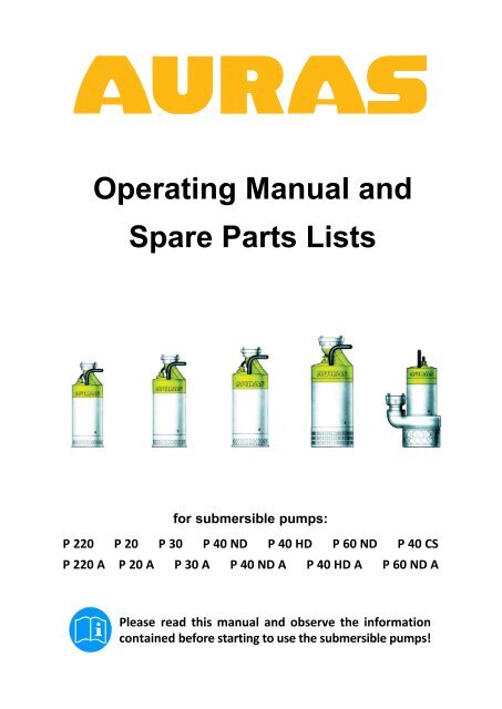
<strong>Operating</strong> <strong>Manual</strong> <strong>and</strong><br />
<strong>Spare</strong> <strong>Parts</strong> <strong>Lists</strong><br />
for submersible pumps:<br />
P 220 P 20 P 30 P 40 ND P 40 HD P 60 ND P 40 CS<br />
P 220 A P 20 A P 30 A P 40 ND A P 40 HD A P 60 ND A<br />
Please read this manual <strong>and</strong> observe the information<br />
contained before starting to use the submersible pumps!
Contents<br />
Page 2<br />
Page<br />
1 Use .................................................................... 4<br />
1.1 Intended Use ..................................................... 4<br />
1.2 Unintended Use ................................................... 4<br />
1.3 CE Mark ......................................................... 5<br />
1.4 Disposal ......................................................... 5<br />
2 Safety Information on the Submersible Pump ................................ 6<br />
2.1 Signs <strong>and</strong> Symbols ................................................ 6<br />
2.2 General Safety Information ......................................... 7<br />
3 Becoming Familiar with the Product ........................................ 8<br />
3.1 <strong>Operating</strong> Elements on the Submersible Pump ....................... 8<br />
3.2 <strong>Auras</strong> Automatic System ........................................... 9<br />
3.2.1 Switch positions ............................................ 9<br />
3.3 Transport <strong>and</strong> Storage ............................................. 10<br />
3.4 Power Supply ..................................................... 10<br />
3.5 Frost ............................................................ 11<br />
3.6 Overheating/Overloading ........................................... 11<br />
4 Preparatory Measures .................................................... 12<br />
4.1 Controlling the Direction of Rotation<br />
(only for models with a three-phase current supply) .................... 12<br />
4.2 Connecting <strong>and</strong> Securing the Discharge Hose ........................ 12<br />
5 Using the Submersible Pump .............................................. 14<br />
5.1 Correct Positioning ................................................ 14<br />
5.2 Switching On/Off .................................................. 15<br />
5.3 After Use/Cleaning ................................................ 15<br />
6 Useful Accessories ....................................................... 16<br />
6.1 Base Suckers ..................................................... 16<br />
6.1.1 Installing the base sucker .................................... 16<br />
6.1.2 Using the base sucker ....................................... 16<br />
6.2 External Float Switch .............................................. 16<br />
6.2.1 Connecting the float switch ................................... 16<br />
6.3 Non-return Valve .................................................. 17<br />
6.3.1 Installing a non-return valve .................................. 17<br />
6.4 Hose Diameter Enlargement/Reduction .............................. 17<br />
7 Maintenance <strong>and</strong> Service ................................................. 18<br />
7.1 Checks .......................................................... 18<br />
7.1.1 Inspection intervals .......................................... 18<br />
7.1.2 Checking seals <strong>and</strong> oil ....................................... 18<br />
7.2 Controlling <strong>and</strong> Minimising Wear .................................... 19<br />
8 First Aid for the Submersible Pump ......................................... 20<br />
8.1 Rating Plate ...................................................... 20<br />
9 Contact ................................................................. 21<br />
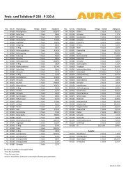
10 Performance Curves & Technical Data ..................................... 22
Contents<br />
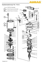
11 Drawings <strong>and</strong> <strong>Parts</strong> <strong>Lists</strong> ................................................. 24<br />
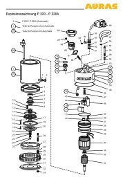
11.1 Exploded Diagram, P 220 - P 220A .................................. 24<br />
11.2 <strong>Parts</strong> List, P 220 - P 220A .......................................... 25<br />
11.3 Exploded Diagram, P 20 - P 20A .................................... 26<br />
11.4 <strong>Parts</strong> List, P 20 - P 20A ............................................ 27<br />
11.5 Exploded Diagram, P 30 - P 30A .................................... 28<br />
11.6 <strong>Parts</strong> List, P 30 - P 30A ............................................ 29<br />
11.7 Exploded Diagram, P 40 ND - P 40 NDA ............................. 30<br />
11.8 <strong>Parts</strong> List, P 40 ND - P 40 NDA ..................................... 31<br />
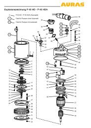
11.9 Exploded Diagram, P 40 HD - P 40 HDA ............................. 32<br />
11.10 <strong>Parts</strong> List, P 40 HD - P 40 HDA ..................................... 33<br />
11.11 Exploded Diagram, P 60 ND - P 60 NDA ............................. 34<br />
11.12 <strong>Parts</strong> List, P 60 ND - P 60 NDA ..................................... 35<br />
11.13 Exploded Diagram, P 40 CS ........................................ 36<br />
11.14 <strong>Parts</strong> List, P 40 CS ................................................ 37<br />
12 EC Declaration of Conformity .............................................. 38<br />
Page 3
Use<br />
Introduction<br />
We are very pleased that you have chosen a submersible pump from <strong>Auras</strong>, a high<br />
quality br<strong>and</strong>!<br />
Please observe the information in this operating manual to ensure your<br />
submersible pump enjoys a long, trouble-free service life!<br />
NOTE<br />
<strong>Auras</strong> <strong>Pumpen</strong> GmbH & Co. KG is not considered liable for personal injury or property<br />
damage resulting from improper use of the submersible pump!<br />
Only use the <strong>Auras</strong> submersible pump in accordance with the types of use described<br />
in this manual!<br />
The <strong>Auras</strong> pump is a portable submersible pump. Prior to a fixed installation, the<br />
installation conditions must be checked <strong>and</strong> evaluated by experts. <strong>Auras</strong> <strong>Pumpen</strong><br />
GmbH & Co. KG is not considered liable for any consequential damage (personal<br />
injury or property damage) resulting from improper installation.<br />
1 Use<br />
1.1 Intended Use<br />
1.2 Unintended Use<br />
<strong>Auras</strong> submersible pumps are conceived for the areas of use <strong>and</strong> working<br />
conditions described below:<br />
<br />
<br />
<br />
<br />
<br />
<br />
<br />
<strong>Auras</strong> submersible pumps may only be used in their condition on delivery.<br />
Modifications are not permitted.<br />
For pumping construction trenches, cellars, ponds, swimming pools, etc. dry.<br />
For preventing groundwater seeping into construction trenches for a reasonable<br />
time in accordance with local regulations (groundwater maintenance).<br />
For use as a groundwater pump, e.g. to water gardens <strong>and</strong> agricultural areas.<br />
<strong>Auras</strong> submersible pumps may only operated in water within a temperature<br />
range from 0 to 35 °C.<br />
The maximum immersion depth is 10 meters (below the water surface).<br />
Model P40 CS only: Use in sewage containing faeces.<br />
<strong>Auras</strong> submersible pumps have NOT been conceived for the following:<br />
<br />
<br />
<br />
Use in potentially explosive atmospheres.<br />
Use in combustible liquids.<br />
Use in liquids such as: oil, chemicals, foodstuffs, sewage containing faeces<br />
(except Model P40 CS), liquids containing long-str<strong>and</strong>ed components.<br />
Page 4
Use<br />
1.3 CE Mark<br />
1.4 Disposal<br />
This submersible pump from <strong>Auras</strong> fulfils all the necessary requirements stipulated<br />
in the applicable EU Directives:<br />
(DIRECTIVE 2006/42/EC OF THE EUROPEAN PARLIAMENT AND OF THE<br />
COUNCIL of 17 May 2006 on machinery, <strong>and</strong> amendment to Directive 95/16/EC<br />
(revised version) significant to the EEA).<br />
Conformity of the product to the above directives is confirmed by the CE Mark<br />
applied to the device. The Declaration of Conformity can be viewed in full at the<br />
following address:<br />
<strong>Auras</strong> <strong>Pumpen</strong> GmbH & Co. KG<br />
Ferdin<strong>and</strong>-Porsche-Str. 13<br />
D-60386 Frankfurt / Main<br />
When your <strong>Auras</strong> submersible pump has come to the end of its service life, bring<br />
the old unit to a collection point provided by your local waste disposal authorities<br />
(e.g. recycling centre, waste disposal plant).<br />
The adjacent symbol indicates that the old unit must be disposed of separated from<br />
household waste. According to the laws on electrical <strong>and</strong> electronic equipment, the<br />
owners of old units are legally obliged to dispose of old electronic <strong>and</strong> electrical<br />
devices in a separate waste container.<br />
Please help <strong>and</strong> make a contribution to environmental protection by not throwing<br />
old equipment in household waste.<br />
Page 5
Safety<br />
2 Safety Information on the Submersible Pump<br />
Dear Customer,<br />
Your safety is very important to us!<br />
Therefore, please read the safety information carefully <strong>and</strong> thoroughly. Always<br />
observe the general information regarding safety provided in this chapter as well as<br />
the specific safety information in the following chapters.<br />
NOTE<br />
<strong>Auras</strong> <strong>Pumpen</strong> GmbH & Co. KG is not considered liable for damage or injury<br />
caused by any of the following reasons:<br />
<br />
<br />
<br />
<br />
Disregard for the safety information<br />
Improper h<strong>and</strong>ling or use<br />
Use with non-approved accessories / spare parts<br />
Failure to observe the legal inspection requirements <strong>and</strong> maintenance<br />
recommendations<br />
2.1 Signs <strong>and</strong> Symbols<br />
This operating manual contains the following signs <strong>and</strong> symbols to indicate various<br />
risks <strong>and</strong> information:<br />
Level of Danger Associated Symbol Signal Word Definition<br />
Risk of fatal injury DANGER Failure to observe the safety<br />
information will result in fatal<br />
or serious personal injury.<br />
Serious injury WARNING Failure to observe the safety<br />
information could result in<br />
fatal or serious personal<br />
injury.<br />
Serious injury through electric<br />
shock<br />
Minor injury <strong>and</strong> property<br />
damage<br />
Information<br />
Tip<br />
<br />
CAUTION<br />
INFORMA<br />
TION<br />
TIP<br />
Extra indication of the basic<br />
risks from electricity.<br />
Failure to observe the safety<br />
information could result in<br />
minor personal injury <strong>and</strong>/or<br />
property damage.<br />
Information on preventing<br />
injuries to persons <strong>and</strong><br />
damage to the environment<br />
<strong>and</strong>/or equipment.<br />
Helpful information on using<br />
the submersible pump.<br />
Page 6
Safety<br />
2.2 General Safety Information<br />
NOTE<br />
DANGER<br />
DANGER<br />
WARNING<br />
CAUTION<br />
Not all the possible risks which could occur when using the equipment can be listed<br />
in this operating manual. Always work in a cautious manner <strong>and</strong> observe the local<br />
safety regulations.<br />
Risk of electric shock<br />
Incorrectly repaired submersible pumps could be the source of incalculable<br />
safety risks. Always have repairs completed by authorised, skilled personnel!<br />
Even low electrical currents can lead to serious or even fatal injuries!<br />
Never lift the submersible pump by the cable.<br />
Lay the cables so that they cannot be damaged.<br />
Never put a damaged submersible pump into operation.<br />
Non-functional safety equipment<br />
Safety equipment which has been put out of service represents a major safety<br />
risk! Never put the safety equipment on the submersible pump out of service!<br />
Risks for children<br />
This device may be used by children aged 13 or over <strong>and</strong> by persons with<br />
restricted physical, sensory or mental capability or lack of experience <strong>and</strong><br />
knowledge when they are under supervision or have received the necessary<br />
instruction regarding safe use of the device <strong>and</strong> underst<strong>and</strong> the risks involved.<br />
Children must not play with the device. Cleaning <strong>and</strong> user maintenance must<br />
not be completed by children without the appropriate supervision.<br />
Risk of explosion<br />
Pumps can be the cause of serious explosions! The submersible pumps are not<br />
designed for use in potentially explosive atmospheres! Never use the<br />
submersible pumps in such areas!<br />
Drowning<br />
Persons could be drawn under water <strong>and</strong> drown. Never operate the<br />
submersible pump in containers/bodies of water in which people are st<strong>and</strong>ing.<br />
Mutilation<br />
The submersible pump could start up accidentally <strong>and</strong> cause severe injuries!<br />
Disconnect the submersible pump from the mains power supply before opening<br />
it or beginning any work on it!<br />
Back injuries, crushing<br />
The submersible pump is heavy <strong>and</strong> could cause serious injuries, e.g. if it falls<br />
over. Always use suitable tools <strong>and</strong> aids to transport the submersible pump.<br />
Damage to the submersible pump<br />
Inappropriate electrical voltages could damage the submersible pump. Only<br />
operate the submersible pump within the specified voltage range (indicated on<br />
the respective rating plate).<br />
Page 7
Becoming Familiar with the Product<br />
3 Becoming Familiar with the Product<br />
This chapter will help you become familiar with the operating elements on the<br />
submersible pump <strong>and</strong> provides information on transporting it properly.<br />
3.1 <strong>Operating</strong> Elements on the Submersible Pump<br />
<strong>Auras</strong> submersible pump are equipped with the following elements:<br />
1<br />
2<br />
3 4<br />
5<br />
6<br />
1. Power connector with three-phase reversing switch (models P220 <strong>and</strong> P60 ND<br />
have no three-phase reversing switch)<br />
2. Discharge<br />
3. In the case of a submersible pump with <strong>Auras</strong> Automatic: Selector switch with<br />
setting "A" for Automatic operation <strong>and</strong> "C" for Continuous operation<br />
4. H<strong>and</strong>le<br />
5. Start label<br />
6. Rating plate<br />
NOTE<br />
The submersible pump starts when it is connected to the mains power supply via<br />
the power connector.<br />
Page 8
Becoming Familiar with the Product<br />
3.2 <strong>Auras</strong> Automatic System<br />
<br />
TIP<br />
The <strong>Auras</strong> Automatic system (indicated by the "A" in the model name) operates<br />
without any moving parts.<br />
The water level is monitored by two electrodes mounted in the pump housing. If the<br />
top <strong>and</strong> bottom electrodes are surrounded by water (Fig. 1), the submersible pump<br />
starts up. The water level sinks (Fig. 2). Pump operation is stopped when the water<br />
level has dropped below the bottom electrode (Fig. 3).<br />
The control voltage of the electrodes is only 18 V <strong>and</strong> completely harmless for human<br />
beings.<br />
Fig. 1 Fig. 2 Fig. 3<br />
3.2.1 Switch positions<br />
In order to activate <strong>Auras</strong> automatic mode, move the selector switch to the position<br />
illustrated in Fig. 1.<br />
In order to deactivate <strong>Auras</strong> automatic mode, move the selector switch to the<br />
position illustrated in Fig. 2.<br />
Fig. 1 Selector switch<br />
Fig. 2<br />
Page 9
Becoming Familiar with the Product<br />
3.3 Transport <strong>and</strong> Storage<br />
DANGER<br />
WARNING<br />
Electric shock<br />
Defective cables can lead to serious injuries <strong>and</strong> damage. Lever attempt to lift the<br />
submersible pump using the power cable or hose because the parts could be damaged<br />
as a result.<br />
Always use the h<strong>and</strong>le to transport, lift <strong>and</strong> set down the submersible pump.<br />
Back injuries, crushing<br />
The submersible pump is heavy <strong>and</strong> could cause serious injuries, e.g. if it falls<br />
over. Always use suitable tools <strong>and</strong> aids to transport the submersible pump.<br />
3.4 Power Supply<br />
Observe the following points in the case of transport <strong>and</strong> storage:<br />
Always use the h<strong>and</strong>le to transport the pump.<br />
Store the submersible pump at a location protected from frost.<br />
DANGER<br />
Fatal electric shock<br />
Incorrectly installed power sockets could be the cause of fatal electric shocks.<br />
Only operate the submersible pump via properly installed <strong>and</strong> approved power<br />
sockets.<br />
Only allow properly skilled electricians to complete work on electrical lines <strong>and</strong> systems.<br />
NOTE The fuse at the power source must comply with the specified values (refer to<br />
the Technical Data from Seite 22). When the pump motor is started up, it briefly<br />
requires a much higher current for a short time than for the operating current.<br />
The mains voltage to which the submersible pump is connected may deviate<br />
maximally +/- 5% from the voltage specified on the submersible pump's rating<br />
plate. In the case of greater deviations, the submersible pump will be damaged.<br />
If you operate the submersible pump via a portable power generator, pay<br />
attention that is capable of producing the higher starting current which is<br />
required briefly when the submersible pump is switched on.<br />
Only switch the submersible pump on when the correct mains voltage <strong>and</strong><br />
frequency are provided (particularly when using a portable generator).<br />
Otherwise, the pump electronics could be damaged. Contact an electrician in<br />
case of doubt!<br />
If a portable generator is used for the power supply, always disconnect the<br />
submersible pump from the generator before switching the generator off. This<br />
prevents any possible damage to the submersible pump.<br />
If the electrical power is drawn from a distributor (multicontact plug), pay<br />
attention that it will not be overloaded as a result of all the other devices<br />
connected.<br />
Page 10
Becoming Familiar with the Product<br />
3.5 Frost<br />
CAUTION<br />
NOTE<br />
Clogging of the hose<br />
The pump could be overloaded <strong>and</strong> damaged as a result of clogging. If the hose<br />
has frozen <strong>and</strong>/or there is ice in the hose, thaw it or change it before starting the<br />
pump.<br />
The submersible pump is conceived for use at water temperatures from 0 - 35 °C. If<br />
the submersible pump is frozen, do not thaw the submersible pump by exposing it<br />
to extreme temperatures (e.g. naked flames or hot air guns). The material from<br />
which the pump is made may not be able to withst<strong>and</strong> such extreme temperature<br />
fluctuations <strong>and</strong> be damaged.<br />
Let the pump thaw slowly at moderate temperatures.<br />
Use of the submersible pump at temperatures under 0 °C is only permitted when<br />
the submersible pump is fully immersed in water or under the frozen surface.<br />
3.6 Overheating/Overloading<br />
The thermal sensors in the submersible pumps are switched to the motor contactor<br />
in such a way that the submersible pump is automatically switched off in the event<br />
of overheating or overloading.<br />
Page 11
Preparatory Measures<br />
4 Preparatory Measures<br />
This section provides information on preparing the submersible pump for use.<br />
4.1 Controlling the Direction of Rotation (only for models with a<br />
three-phase current supply)<br />
DANGER<br />
WARNING<br />
NOTE<br />
Fatal electric shocks<br />
Electric shocks possible if the phases are swapped.<br />
The AC phases may only be altered by correspondingly skilled personnel. Disconnect<br />
the submersible pump from the mains power supply beforeh<strong>and</strong> <strong>and</strong> lock it<br />
against being connected/switched on again without authorisation.<br />
Fire <strong>and</strong> short circuit<br />
Cable fires <strong>and</strong> short circuits possible due to incorrect extension cables.<br />
Only use extension cables with appropriate dimensioning. Pay attention that the<br />
plug connections are splashproof.<br />
Always wind the cable up fully to prevent a so called coil effect which could lead to<br />
a cable fire.<br />
In the event of incorrect direction of rotation, the submersible pump motor could<br />
overload <strong>and</strong> be damaged as a result.<br />
Submersible pumps are switched to rotate clockwise at the factory in accordance<br />
with VDE directives.<br />
Despite this, incorrect rotation is possible as a result of three-phase AC. Therefore,<br />
check the direction of rotation each time before the pump is put into operation.<br />
Proceed as follows to check the direction of rotation:<br />
1. Only in the case of automatic pumps: Set the selector switch to Position "C" for<br />
continuous operation.<br />
2. Tip the pump to a slight angle.<br />
3. Switch on the mains power supply briefly (approx. 1 second) (refer to Switching<br />
On/Off on Page 15).<br />
4. If the pump motor rotates in the right direction, the submersible pump jolts<br />
visibly <strong>and</strong> perceptibly in the direction of the mark (arrow on the start label).<br />
5. If the submersible pump jolts in the opposite direction to the mark (arrow on the<br />
start label), actuate the three-phase reversing switch on the power connector, if<br />
available, or call a properly qualified electrician to swap the corresponding<br />
phases.<br />
4.2 Connecting <strong>and</strong> Securing the Discharge Hose<br />
WARNING<br />
CAUTION<br />
Flailing of the discharge hose<br />
The discharge hose can flail around when under extreme pressure causing serious<br />
injuries <strong>and</strong>/or property damage. Hold the hose firmly or fix it adequately.<br />
Risk of flooding<br />
The hose could loosen from the discharge if it is not tightened properly.<br />
Ensure that the discharge hose is tightened correctly <strong>and</strong> sufficiently <strong>and</strong> that the<br />
area in which the pumped water will be drained can take the water without any risk.<br />
Page 12
Preparatory Measures<br />
<br />
NOTE The pumped water could contain pollutants which represent a risk to the environment.<br />
Ensure that water containing pollutants is collected <strong>and</strong> disposed of<br />
properly, according to the applicable regulations.<br />
When laying the hose, pay attention there are no kinks in it.<br />
Lay the hose so that there is no risk of tripping over it.<br />
Protect the hose from being driven over.<br />
Do not lay the hose over sharp edges or on surfaces which could damage it.<br />
TIP<br />
If the submersible pump is to be used in confined shafts in which the hose will run<br />
vertically upwards, we recommend use of a non-return valve (particularly for Automatic<br />
operation). This prevents an unwanted return flow of the water if the submersible<br />
pump is switched off.<br />
Proceed as follows to connect the corresponding discharge hose to the discharge<br />
of the submersible pump:<br />
1. Fit the hose connection on the discharge of the submersible pump.<br />
When doing so, pay attention that the surfaces are clean <strong>and</strong> the seals are in<br />
good condition. The hose connection must make full contact.<br />
2. Turn the hose connection clockwise to tighten it. Use a coupling wrench, if<br />
necessary.<br />
3. The discharge hose must be laid to a location which can take the quantity <strong>and</strong><br />
type of water pumped without any risks. Secure the end of the hose from<br />
flailing, unauthorised access <strong>and</strong> slipping.<br />
Page 13
Using the Submersible Pump<br />
5 Using the Submersible Pump<br />
This section explains how to operate the submersible pump safely, considerately<br />
<strong>and</strong> efficiently.<br />
5.1 Correct Positioning<br />
DANGER<br />
NOTE<br />
Fatal electric shocks<br />
Never attempt to lift the submersible pump by the power cable or hose.<br />
Always use the h<strong>and</strong>le to transport, lift <strong>and</strong> set down the submersible pump.<br />
Information on positioning:<br />
The diffuser <strong>and</strong> impeller could be subject to extreme wear if the pump is<br />
positioned incorrectly. Do not place the submersible pump on clay or s<strong>and</strong>y<br />
ground. Hang the submersible pump in such pump sumps by the h<strong>and</strong>le so its<br />
base is 2 - 3 cm above the ground.<br />
The impeller could become blocked in bodies of water in which a great deal of<br />
foliage etc. has collected. Place the submersible pump inside an additional<br />
cage in such circumstances. This also helps to filter out foliage <strong>and</strong> such.<br />
If you use the <strong>Auras</strong> automatic system, set the pump up as vertically as<br />
possible. If placed in a lying position, automatic mode cannot operate correctly<br />
<strong>and</strong> the submersible pump could run dry.<br />
Proceed as follows to position the submersible pump:<br />
<br />
TIP<br />
1. If the pump is to be lowered into a shaft, attach a sufficiently strong rope or<br />
such to the h<strong>and</strong>le <strong>and</strong> lower the submersible pump carefully. Do not lower the<br />
submersible pump by the cable or hose.<br />
If you want to use the <strong>Auras</strong> pump in automatic mode, do not forget to set the selector<br />
switch to the necessary position.<br />
2. Pay attention that the submersible pump st<strong>and</strong>s firmly in the water. Secure it<br />
from tipping over, if necessary.<br />
3. Set the submersible pump down in the water on a firm piece of ground or<br />
suspend it in the water from a sufficiently strong rope, 2 - 3 cm from the ground.<br />
Rope, chain or such<br />
Distance to ground,<br />
at least 2-3 cm<br />
Positioning on firm ground<br />
Positioning on loose ground<br />
Page 14
Using the Submersible Pump<br />
5.2 Switching On/Off<br />
CAUTION<br />
Never leave the submersible pump unattended when in operation. Remain on site<br />
to prevent any accidents etc.<br />
When you have positioned <strong>and</strong> set up the submersible pump as described,<br />
connect the power connector to the power socket.<br />
The submersible pump starts operation automatically or begins operation when the<br />
<strong>Auras</strong> automatic system is activated.<br />
To switch the submersible pump off, simply disconnect the power connector from<br />
the power socket.<br />
5.3 After Use/Cleaning<br />
Elements pumped up with the water, e.g. cement, plaster or mud, could dry <strong>and</strong><br />
block moving parts of the submersible pump. Flush the submersible pump<br />
thoroughly with clean water after use.<br />
Page 15
Useful Accessories<br />
6 Useful Accessories<br />
6.1 Base Suckers<br />
Our homepage at www.tauchpumpen.de provides a wide range of useful<br />
accessories. This chapter describes the installation of the most frequently used<br />
accessories:<br />
If you want to pump your cellar practically dry, for example, a base sucker from<br />
<strong>Auras</strong> can be used. The <strong>Auras</strong> base suckers pump the water practically to floor<br />
level.<br />
6.1.1 Installing the base sucker<br />
1. Disconnect the submersible pump from the power supply.<br />
2. Lay the submersible pump on its side.<br />
3. Loosen the three nuts in the base plate on the underside of the submersible<br />
pump.<br />
4. Remove the base plate.<br />
5. Mount the base sucker on the underside of the submersible pump. The collar<br />
must point to the air intake of the submersible pump.<br />
6. Tighten the three nuts in the base plate on the underside of the submersible<br />
pump.<br />
6.1.2 Using the base sucker<br />
Position the submersible pump with <strong>Auras</strong> base sucker installed at the lowest<br />
possible point of the area to be pumped.<br />
If you use a submersible pump with the <strong>Auras</strong> automatic system, switch to<br />
Continuous operation.<br />
Plug the power connector of the submersible pump in a power socket. The<br />
submersible pump starts its pumping operation.<br />
6.2 External Float Switch<br />
If your pump is not equipped with the <strong>Auras</strong> automatic system but you need an<br />
automatic operation option despite this, we recommend the float switch from <strong>Auras</strong>.<br />
6.2.1 Connecting the float switch<br />
NOTE<br />
Running dry could damage the submersible pump. Ensure the float switch switches<br />
the submersible pump off in good time. Fix the cable of the float switch so that the<br />
float hangs vertically down when the water level is low <strong>and</strong>, as a result, switches<br />
the pump off.<br />
Page 16
Useful Accessories<br />
1. Plug the power connector of the submersible pump in the connection on the<br />
float switch (see below).<br />
Float switch connection with 230 V<br />
submersible pump<br />
Float switch connection with 400 V<br />
submersible pump<br />
2. Set-up the submersible pump as described.<br />
3. Position the float in the area/container to be pumped dry so that it can move<br />
freely (Position A). Fix the cable of the float switch so that when the water level<br />
is low, the float hangs above the ground/base (Position B) <strong>and</strong> does not make<br />
contact with it.<br />
Position A<br />
Position B<br />
4. Plug the float switch power connector in the power socket to switch the<br />
submersible pump on.<br />
6.3 Non-return Valve<br />
If the submersible pump is to be used in narrow shafts in which the discharge hose<br />
is fed vertically upwards, we recommend the installation of a non-return valve. This<br />
ensures that the water still in the hose after the pump has stopped does not flow<br />
back into the sump. It is of particular advantage when using a submersible pump<br />
with automatic system or a float switch because the submersible pump is not<br />
reactivated due to water flowing back.<br />
6.3.1 Installing a non-return valve<br />
1. Assemble the non-return valve directly on the discharge of the submersible<br />
pump.<br />
2. Connect the discharge hose to the non-return valve <strong>and</strong> lay it as described.<br />
6.4 Hose Diameter Enlargement/Reduction<br />
<br />
TIP<br />
<strong>Auras</strong> has a wide range of solutions in cases where hose diameters must be<br />
enlarged or reduced.<br />
Please note that the pressure increases when the diameter is reduced <strong>and</strong> decreases<br />
when the diameter is enlarged.<br />
If the hose diameter is reduced, the end of the hose must be particularly well fixed.<br />
Page 17
Maintenance <strong>and</strong> Service<br />
7 Maintenance <strong>and</strong> Service<br />
DANGER<br />
Fatal electric shocks<br />
Incorrectly serviced submersible pumps represent a risk of fatal injury!<br />
Always have maintenance <strong>and</strong> service work completed by skilled personnel trained<br />
for the tasks.<br />
Follow the information in this chapter to ensure your submersible pump enjoys a<br />
long, trouble-free service life.<br />
7.1 Checks<br />
WARNING<br />
CAUTION<br />
NOTE<br />
Mutilation<br />
The submersible pump could start up accidentally <strong>and</strong> cause severe injuries! Disconnect<br />
the submersible pump from the mains power supply <strong>and</strong> lock it against being<br />
switched on without authorisation before opening or working on it!<br />
Risk of slipping<br />
Escaping oil represents a risk of slipping <strong>and</strong>, thus, to bad falls. Clear it up immediately<br />
<strong>and</strong> properly.<br />
Information on maintenance<br />
When completing checks, pay attention that escaping oil is always cleaned up<br />
properly, according to the appropriate regulations. Otherwise, it could lead to<br />
environmental damage. Clear up escaping oil immediately <strong>and</strong> properly!<br />
Observe local inspection requirements (e.g. for Germany: the BGV A3).<br />
7.1.1 Inspection intervals<br />
Period<br />
After two weeks<br />
Monthly<br />
Every two months<br />
Condition<br />
Submersible pump is new<br />
New seals have been installed<br />
Operation in very dirty water<br />
Operation in clean water<br />
7.1.2 Checking seals <strong>and</strong> oil<br />
The seals should be checked in a protected room with sealed floor.<br />
Page 18<br />
Proceed as follows to check the seals:<br />
1. Disconnect the submersible pump from the mains power supply <strong>and</strong> lock it<br />
against being switched on again without authorisation.<br />
2. Lay the submersible pump on its side so that an oil sump can be placed under<br />
the oil drain plug. Secure the pump from moving its position inadvertently.<br />
3. Place a sufficiently large oil sump under the oil drain plug (for oil quantity, refer<br />
to Technical Data Seite 22).<br />
4. Remove the oil drain plug, including the sealing ring, from the submersible<br />
pump housing. The oil flows into the oil sump provided.<br />
5. Check the sealing ring <strong>and</strong> replace with a new one, if necessary.
Maintenance <strong>and</strong> Service<br />
6. Check the seals <strong>and</strong> oil:<br />
Seals <strong>and</strong> oil are correct when ONLY oil flows out of the submersible pump.<br />
Seals <strong>and</strong> oil must be renewed when:<br />
- the oil quantity has dropped appreciably,<br />
- the oil has a light, yellow-brown colouration,<br />
- the oil is viscous,<br />
- there is a distinct water separation in the oil.<br />
7. Complete the necessary repairs:<br />
- replace the seals,<br />
- refill/change the oil (for details, refer to the Technical Data Seite 22).<br />
8. Insert <strong>and</strong> tighten the oil drain plug including the sealing ring again.<br />
7.2 Controlling <strong>and</strong> Minimising Wear<br />
WARNING<br />
Mutilation<br />
The submersible pump could start up accidentally <strong>and</strong> cause severe injuries! Disconnect<br />
the submersible pump from the mains power supply <strong>and</strong> lock it against being<br />
switched on without authorisation before opening or working on it!<br />
Check the level of wear to the impeller, diffuser, wearing lining <strong>and</strong> impeller cover<br />
at regular intervals.<br />
Too much slack between the impeller <strong>and</strong> diffuser results in a considerable<br />
increase in wear.<br />
Regular fine adjustment of the diffuser <strong>and</strong> impeller by skilled personnel can<br />
lengthen the service life of these parts considerably.<br />
Page 19
First Aid for the Submersible Pump<br />
8 First Aid for the Submersible Pump<br />
This chapter explains how to recognise <strong>and</strong> clear faults.<br />
DANGER<br />
Fatal electric shocks<br />
Always disconnect the power connector before starting to locate faults!<br />
Always have electrical faults checked <strong>and</strong> cleared by an appropriately skilled electrician.<br />
Fault / Problem Possible Cause Solution<br />
Too little power<br />
Diffuser <strong>and</strong>/or impeller worn<br />
Incorrect direction of rotation of<br />
motor<br />
Discharge hose kinked<br />
Discharge hose too long<br />
Motor cable longer than st<strong>and</strong>ard<br />
length<br />
Current fluctuations too extreme<br />
Change the components<br />
concerned<br />
Actuate the three-phase reversing<br />
switch<br />
Re-lay the discharge hose <strong>and</strong><br />
secure<br />
Use shorter discharge hose<br />
Use shorter motor cable<br />
Current fluctuations, see Page 10<br />
Pump motor does not<br />
start<br />
Automatic mode is not<br />
activated<br />
Pump does not start<br />
<strong>and</strong> there is water in<br />
the cover<br />
Pump does not start<br />
<strong>and</strong> there is water or<br />
oil in the motor<br />
housing<br />
8.1 Rating Plate<br />
Power cable is defective<br />
Cable inside the submersible pump<br />
is defective<br />
Loose connections of cables/<br />
connectors<br />
Electrode slot in the motor housing<br />
is blocked<br />
Electrode is damaged<br />
Electrode is stuck<br />
Cable is damage<br />
Cable inlet is defective<br />
O-ring between the motor housing<br />
<strong>and</strong> cover is defective<br />
Seal(s) defective<br />
Sealing ring between the oil<br />
housing <strong>and</strong> motor compartment<br />
Always have these faults cleared<br />
by an appropriately skilled<br />
electrician!<br />
Clean the electrode slot<br />
Have the electrode changed by<br />
skilled personnel<br />
Clean the electrode<br />
Have the cable replaced by a<br />
skilled electrician<br />
Have the cable inlet replaced by a<br />
skilled electrician<br />
Change the O-ring<br />
Change the seal(s)<br />
Change the sealing ring<br />
There is water in the oil Seal(s) defective Change the seal(s)<br />
The rating plate serves for the unique identification of the submersible pump. It is<br />
located at the top of the submersible pump. If you contact us by telephone in<br />
respect of queries, please have the information on the rating plate close to h<strong>and</strong>.<br />
TAUCHPUMPE<br />
TYP<br />
U V1~<br />
Nr.<br />
I A f Hz IP68<br />
P 1<br />
H max<br />
Isokl:<br />
kW<br />
m<br />
n<br />
m<br />
-1<br />
Isokl: min<br />
Q max<br />
Year of manufacture:<br />
<strong>Auras</strong> <strong>Pumpen</strong> GmbH & Co. KG<br />
kg<br />
l/min<br />
Ferdin<strong>and</strong>-Porsche-Str. 13<br />
D-60386 Frankfurt am Main<br />
Sample rating plate (also applicable for three-phase pumps; 400V V3~)<br />
Page 20
Contact<br />
9 Contact<br />
If you have any queries with regard to your submersible pump, please do not<br />
hesitate to contact us. Our service team can provide all the help you need.<br />
<strong>Auras</strong> <strong>Pumpen</strong> GmbH & Co. KG<br />
Ferdin<strong>and</strong>-Porsche-Str. 13<br />
D-60386 Frankfurt / Main<br />
Tel. 069 678 307-190<br />
Fax 069 678 307-199<br />
E-mail: info@auras-pumpen.de<br />
Internet: www.tauchpumpen.de<br />
Office hours:<br />
Monday - Thursday<br />
Friday<br />
7:00 a.m. to 4:00 p.m. continuously<br />
7:00 a.m. to 3:00 p.m. continuously<br />
Page 21
Performance Curves & Technical Data<br />
10 Performance Curves & Technical Data<br />
P 220/P 220 A + P 20/P 20 A<br />
Contaminated water submersible pump<br />
Technical Data, P 220/P 220 A<br />
Weight ....................................... 22 kg<br />
Diameter ................................... 210 mm<br />
Height ..................................... 510 mm<br />
Hose connection .............................. 2 inch<br />
Impeller ........................ Chromium-nickel steel<br />
Wearing parts ........................ Synthetic rubber<br />
Nominal voltage ............................. 230 Volt<br />
Frequency .................................... 50 Hz<br />
Fuses, required inert ............................ 16 A<br />
Nominal current ................................ 6.4 A<br />
Power input P1 .............................. 1.45 kW<br />
Cable 15 m .............................. 3 x 1.5 mm 2<br />
Oil quantity ................................. 0.25 litre<br />
Oil quality .................................. 10W 40<br />
Emission sound pressure level ............. < 70 dB (A)<br />
Technical Data, P 20/P 20 A<br />
Weight ....................................... 23 kg<br />
Diameter ................................... 210 mm<br />
Height ..................................... 510 mm<br />
Hose connection .............................. 2 inch<br />
Impeller ........................ Chromium-nickel steel<br />
Wearing parts ........................ Synthetic rubber<br />
Nominal voltage ............................. 400 Volt<br />
Frequency .................................... 50 Hz<br />
Fuses, required inert ............................ 10 A<br />
Nominal current ................................ 2.6 A<br />
Power input P1 ............................... 1.3 kW<br />
Cable 15 m .............................. 4 x 1.5 mm 2<br />
Oil quantity ................................. 0.25 litre<br />
Oil quality .................................. 10W 40<br />
Emission sound pressure level ............. < 70 dB (A)<br />
P 30/P 30 A<br />
Contaminated water submersible pump<br />
Technical Data, P 30/P 30 A<br />
Weight ...................................... 37 kg<br />
Diameter ................................. 246 mm<br />
Height ................................... 540 mm<br />
Hose connection ............................ 3 inch<br />
Impeller ...................... Chromium-nickel steel<br />
Wearing parts ...................... Synthetic rubber<br />
Nominal voltage ........................... 400 Volt<br />
Frequency .................................. 50 Hz<br />
Fuses, required inert .......................... 16 A<br />
Nominal current .............................. 5.7 A<br />
Power input P1 ............................. 3.5 kW<br />
Cable 15 m ............................ 4 x 1.5 mm 2<br />
Oil quantity ............................... 0.30 litre<br />
Oil quality ................................. 10W 40<br />
Emission sound pressure level ........... < 70 dB (A)<br />
The values stipulated in the curves are maximum values. Numerous factors can contribute to a reduction of the output specified when<br />
in operation (e.g. loss of friction due to the properties of the interior of the hose, etc.).<br />
Page 22 Edition 03/13
Performance Curves & Technical Data<br />
P 40 ND/P 40 ND A + P 40 HD/P 40 HD A<br />
Contaminated water submersible pump<br />
P 60 ND/P 60 ND A<br />
Contaminated water submersible pump<br />
Technical Data, P 40 ND/P 40 ND A +<br />
P 40 HD/P 40 HD A<br />
Weight ....................................... 44 kg<br />
Diameter ................................... 246 mm<br />
Height ..................................... 620 mm<br />
Hose connection ND ........................... 4 inch<br />
Hose connection HD ........................... 3 inch<br />
Impeller ........................ Chromium-nickel steel<br />
Wearing parts ........................ Synthetic rubber<br />
Nominal voltage ............................. 400 Volt<br />
Frequency .................................... 50 Hz<br />
Fuses, required inert ............................ 25 A<br />
Nominal current ................................ 7.7 A<br />
Power input P1 ............................... 4.7 kW<br />
Cable 15 m .............................. 4 x 2.5 mm 2<br />
Oil quantity ................................. 0.30 litre<br />
Oil quality .................................. 10W 40<br />
Emission sound pressure level ............. < 70 dB (A)<br />
Technical Data, P 60 ND/P 60 ND A<br />
Weight ...................................... 120 kg<br />
Diameter ................................... 350 mm<br />
Height ..................................... 910 mm<br />
Hose connection .............................. 6 inch<br />
Impeller ........................ Chromium-nickel steel<br />
Wearing parts ........................ Synthetic rubber<br />
Nominal voltage ............................. 400 Volt<br />
Frequency .................................... 50 Hz<br />
Fuses, required inert ............................ 63 A<br />
Nominal current .............................. 20.9 A<br />
Power input P1 .............................. 13.5 kW<br />
Cable 15 m ............................... 4 x 6 mm 2<br />
Oil quantity ................................. 2.50 litre<br />
Oil quality .................................. 10W 40<br />
Emission sound pressure level ............. < 70 dB (A)<br />
P 40 CS<br />
Submersible waste water pump<br />
Technical Data, P 40 CS<br />
Weight ..................................... 61.5 kg<br />
Diameter .................................. 420 mm<br />
Height .................................... 670 mm<br />
Hose connection ............................. 4 inch<br />
Impeller ....................... Chromium-nickel steel<br />
Wearing parts ....................... Synthetic rubber<br />
Nominal voltage ............................ 400 Volt<br />
Frequency ................................... 50 Hz<br />
Fuses, required inert ............................ 25 A<br />
Nominal current ............................... 5.2 A<br />
Power input P1 .............................. 2.8 kW<br />
Cable 15 m ............................. 4 x 2.5 mm 2<br />
Oil quantity ................................ 0.50 litre<br />
Oil quality .................................. 10W 40<br />
Emission sound pressure level ............. < 70 dB (A)<br />
The values stipulated in the curves are maximum values. Numerous factors can contribute to a reduction of the output specified when<br />
in operation (e.g. loss of friction due to the properties of the interior of the hose, etc.).<br />
Edition 03/13<br />
Page 23
11.1 Exploded Diagram, P 220 - P 220 A<br />
Drawings <strong>and</strong> <strong>Parts</strong> <strong>Lists</strong><br />
2<br />
1<br />
70<br />
P 220/P 220 A (Automatic)<br />
<strong>Parts</strong> for pumps without Automatic<br />
operation<br />
<strong>Parts</strong> for pumps with Automatic<br />
operation<br />
65<br />
29<br />
48<br />
63<br />
64<br />
59<br />
60<br />
61<br />
62<br />
58<br />
57<br />
54<br />
56<br />
69<br />
66<br />
61<br />
55<br />
1<br />
70<br />
2<br />
3<br />
75<br />
76<br />
77<br />
78<br />
67<br />
68<br />
28<br />
54<br />
53<br />
74<br />
52<br />
73<br />
51<br />
10<br />
11<br />
12<br />
13<br />
14<br />
15<br />
16<br />
19<br />
21<br />
22<br />
23<br />
24<br />
4<br />
5<br />
6<br />
7<br />
8<br />
9<br />
17<br />
18<br />
20<br />
26<br />
27<br />
72<br />
45<br />
44<br />
19<br />
71<br />
13<br />
40<br />
48<br />
47<br />
46<br />
43<br />
42<br />
41<br />
39<br />
38<br />
38<br />
37<br />
50<br />
49<br />
25<br />
28<br />
29<br />
36<br />
29<br />
35<br />
30<br />
31<br />
34<br />
32<br />
33<br />
Page 24 Edition 03/13
Drawings <strong>and</strong> <strong>Parts</strong> <strong>Lists</strong><br />
11.2 <strong>Parts</strong> List, P 220 - P 220 A<br />
Pos. Art. No. Designation Quantity Unit<br />
1 601003 Motor housing 1 Piece<br />
2 601069 Dubo ring 1 Piece<br />
3 601077 Screw 1 Piece<br />
4 601007 Wearing lining 1 Piece<br />
5 601042 Ball bearing 1 Piece<br />
6 601049 Seeger ring 1 Piece<br />
7 601021 O-ring 1 Piece<br />
8 601020 Seal casing 1 Piece<br />
9 601043 Sealing ring 1 Piece<br />
10 601023 Lock washer 3 Piece<br />
11 601022 Screw 3 Piece<br />
12 601044 Sealing unit 1 Piece<br />
13 601064 O-ring 2 Piece<br />
14 601008 Oil housing cover 1 Piece<br />
15 601067 Dubo ring 3 Piece<br />
16 601085 Screw 3 Piece<br />
17 601063 O-ring 1 Piece<br />
18 601009 Impeller cover 1 Piece<br />
19 601078 Screw 5 Piece<br />
20 601011 Impeller 1 Piece<br />
21 601050 Clamping sleeve 1 Piece<br />
22 601058 O-ring 1 Piece<br />
23 601071 Washer 1 Piece<br />
24 601081 Screw 1 Piece<br />
25 601098 Rubber plugs 1 Piece<br />
26 601074 Setscrew 3 Piece<br />
27 601010 Diffuser 1 Piece<br />
28 601073 Washer 6 Piece<br />
29 601086 Nut 8 Piece<br />
30 601012 Sieve 1 Piece<br />
31 601054 Rubber sleeve 3 Piece<br />
32 601013 Base plate 1 Piece<br />
33 601084 Nut 3 Piece<br />
34 601006 Motor shaft unit 1 Piece<br />
35 601041 Ball bearing 1 Piece<br />
36 601059 O-ring 1 Piece<br />
37 601005 Stator 1 Piece<br />
38 601065 O-ring 2 Piece<br />
39 601004 Bearing housing 1 Piece<br />
40 601055 Rubber sleeve 1 Piece<br />
41 601105 Grounding washer 1 Piece<br />
42 601101 Grounding washer 1 Piece<br />
43 601087 Screw 1 Piece<br />
Pos. Art. No. Designation Quantity Unit<br />
44 601142 Contactor 1 Piece<br />
45 601143 Screw 2 Piece<br />
46 601032 Capacitor 1 Piece<br />
47 601080 Screw 2 Piece<br />
48 601072 Lock washer 4 Piece<br />
49 601066 O-ring 1 Piece<br />
50 601088 Rivet 4 Piece<br />
51 601091 Data label 1 Piece<br />
52 601002 Cover 1 Piece<br />
53 601093 Start label) 1 Piece<br />
54 601068 Dubo ring 5 Piece<br />
55 601082 Screw 3 Piece<br />
56 601056 Rubber plugs 3 Piece<br />
57 601028 Mounting bracket 1 Piece<br />
58 601001 Motor circuit breaker 1 Piece<br />
59 601017 Motor cable 15 Metre<br />
60 601016 Cable inlet 1 Piece<br />
61 601019 Washer 2 Piece<br />
62 601018 Rubber sleeve 1 Piece<br />
63 601104 Screw 2 Piece<br />
64 601103 Cable clamp 1 Piece<br />
65 92Z3I02C LM adapter 1 Piece<br />
66 601014 Pressure outlet 1 Piece<br />
67 601015 Gasket 1 Piece<br />
68 601075 Setscrew 2 Piece<br />
69 601132 Electrode 1 Piece<br />
70 601130 Motor housing 1 Piece<br />
71 601133 Switch unit 1 Piece<br />
72 601137 Magnetic switch 1 Piece<br />
73 601144 Data label 1 Piece<br />
74 601131 Cover 1 Piece<br />
75 601136 Screw 2 Piece<br />
76 601138 Rubber cap 1 Piece<br />
77 601135 Rotary knob holder 1 Piece<br />
78 601134 Rotary knob 1 Piece<br />
601100 Oil 0.25 Litre<br />
Accessories<br />
601113 Binding tape 2 Piece<br />
601119 Mounting sleeve 1 Piece<br />
601120 Base sucker 1 Piece<br />
601121 O ring set 1 Piece<br />
Edition 03/13<br />
Page 25
Drawings <strong>and</strong> <strong>Parts</strong> <strong>Lists</strong><br />
11.3 Exploded Diagram, P 20 - P 20 A<br />
2<br />
1<br />
70<br />
P 20/P 20 A (Automatic)<br />
<strong>Parts</strong> for pumps without Automatic<br />
operation<br />
<strong>Parts</strong> for pumps with Automatic<br />
operation<br />
66<br />
29<br />
49<br />
64<br />
65<br />
60<br />
61<br />
62<br />
63<br />
59<br />
58<br />
55<br />
57<br />
70<br />
67<br />
62<br />
56<br />
1<br />
71<br />
2<br />
3<br />
76<br />
77<br />
78<br />
79<br />
68<br />
69<br />
28<br />
55<br />
54<br />
75<br />
53<br />
74<br />
52<br />
4<br />
51<br />
5<br />
73<br />
50<br />
49<br />
6<br />
47<br />
48<br />
10<br />
7<br />
46<br />
8<br />
11<br />
9<br />
19<br />
12<br />
72<br />
13<br />
13<br />
14<br />
42<br />
45<br />
15<br />
17<br />
41<br />
44<br />
16<br />
18<br />
40<br />
43<br />
19<br />
20<br />
39<br />
21<br />
38<br />
22<br />
26<br />
38<br />
23<br />
24<br />
27<br />
37<br />
25<br />
28<br />
29<br />
36<br />
29<br />
35<br />
30<br />
31<br />
34<br />
32<br />
33<br />
Page 26 Edition 03/13
Drawings <strong>and</strong> <strong>Parts</strong> <strong>Lists</strong><br />
11.4 <strong>Parts</strong> List, P 20 - P 20 A<br />
Pos. Art. No. Designation Quantity Unit<br />
1 601003 Motor housing 1 Piece<br />
2 601069 Dubo ring 1 Piece<br />
3 601077 Screw 1 Piece<br />
4 601007 Wearing lining 1 Piece<br />
5 601042 Ball bearing 1 Piece<br />
6 601049 Seeger ring 1 Piece<br />
7 601021 O-ring 1 Piece<br />
8 601020 Seal casing 1 Piece<br />
9 601043 Sealing ring 1 Piece<br />
10 601023 Lock washer 3 Piece<br />
11 601022 Screw 3 Piece<br />
12 601044 Sealing unit 1 Piece<br />
13 601064 O-ring 2 Piece<br />
14 601008 Oil housing cover 1 Piece<br />
15 601067 Dubo ring 3 Piece<br />
16 601085 Screw 3 Piece<br />
17 601063 O-ring 1 Piece<br />
18 601009 Impeller cover 1 Piece<br />
19 601078 Screw 5 Piece<br />
20 601011 Impeller 1 Piece<br />
21 601050 Clamping sleeve 1 Piece<br />
22 601058 O-ring 1 Piece<br />
23 601071 Washer 1 Piece<br />
24 601081 Screw 1 Piece<br />
25 601098 Rubber plugs 1 Piece<br />
26 601074 Setscrew 3 Piece<br />
27 601010 Diffuser 1 Piece<br />
28 601073 Washer 6 Piece<br />
29 601086 Nut 8 Piece<br />
30 601012 Sieve 1 Piece<br />
31 601054 Rubber sleeve 3 Piece<br />
32 601013 Base plate 1 Piece<br />
33 601084 Nut 3 Piece<br />
34 602006 Motor shaft unit 1 Piece<br />
35 601041 Ball bearing 1 Piece<br />
36 601059 O-ring 1 Piece<br />
37 602005 Stator 1 Piece<br />
38 601065 O-ring 2 Piece<br />
39 601004 Bearing housing 1 Piece<br />
40 602034 Switchboard 1 Piece<br />
41 601076 Screw 1 Piece<br />
42 601055 Rubber sleeve 1 Piece<br />
43 601105 Grounding washer 1 Piece<br />
44 601101 Grounding washer 1 Piece<br />
Pos. Art. No. Designation Quantity Unit<br />
45 601087 Screw 1 Piece<br />
46 602033 Air-break contactor 1 Piece<br />
47 601143 Screw 2 Piece<br />
48 601080 Screw 2 Piece<br />
49 601072 Lock washer 4 Piece<br />
50 601066 O-ring 1 Piece<br />
51 601088 Rivet 4 Piece<br />
52 602091 Data label 1 Piece<br />
53 601002 Cover 1 Piece<br />
54 601093 Start label 1 Piece<br />
55 601068 Dubo ring 5 Piece<br />
56 601082 Screw 3 Piece<br />
57 601056 Rubber plugs 3 Piece<br />
58 601028 Mounting bracket 1 Piece<br />
59 602001 Reversing switch 1 Piece<br />
60 602017 Motor cable 15 Metre<br />
61 601016 Cable inlet 1 Piece<br />
62 601019 Washer 2 Piece<br />
63 601018 Rubber sleeve 1 Piece<br />
64 601104 Screw 2 Piece<br />
65 601103 Cable clamp 1 Piece<br />
66 92Z3I02C LM adapter 1 Piece<br />
67 601014 Pressure outlet 1 Piece<br />
68 601015 Gasket 1 Piece<br />
69 601075 Setscrew 2 Piece<br />
70 601132 Electrode 1 Piece<br />
71 601130 Motor housing 1 Piece<br />
72 602133 Switch unit 1 Piece<br />
73 601137 Magnetic switch 1 Piece<br />
74 602144 Data label 1 Piece<br />
75 601131 Cover 1 Piece<br />
76 601136 Screw 2 Piece<br />
77 601138 Rubber cap 1 Piece<br />
78 601135 Rotary knob holder 1 Piece<br />
79 601134 Rotary knob 1 Piece<br />
601100 Oil 0.25 Litre<br />
Accessories<br />
601113 Binding tape 2 Piece<br />
601119 Mounting sleeve 1 Piece<br />
601120 Base sucker 1 Piece<br />
601121 O ring set 1 Piece<br />
Edition 03/13<br />
Page 27
Drawings <strong>and</strong> <strong>Parts</strong> <strong>Lists</strong><br />
11.5 Exploded Diagram, P 30 - P 30 A<br />
2<br />
1<br />
71<br />
71<br />
P 30/P 30 A (Automatic)<br />
<strong>Parts</strong> for pumps without Automatic<br />
operation<br />
<strong>Parts</strong> for pumps with Automatic<br />
operation<br />
64 65<br />
66<br />
63<br />
29<br />
49<br />
62<br />
67<br />
61<br />
77<br />
78<br />
79<br />
80<br />
59<br />
58<br />
55<br />
25<br />
57<br />
56<br />
68<br />
69<br />
60<br />
55<br />
54<br />
1<br />
72<br />
2<br />
3<br />
70<br />
76<br />
53<br />
75<br />
52<br />
51<br />
4<br />
5<br />
74<br />
50<br />
49<br />
6<br />
42<br />
48<br />
10<br />
7<br />
47<br />
8<br />
11<br />
19<br />
9<br />
12<br />
39<br />
73<br />
13<br />
13<br />
14<br />
43<br />
46<br />
17<br />
15<br />
42<br />
45<br />
18<br />
16<br />
44<br />
41<br />
20<br />
19<br />
40<br />
21<br />
13<br />
22<br />
26<br />
39<br />
23<br />
38<br />
27<br />
24<br />
25<br />
28<br />
37<br />
29<br />
29<br />
36<br />
30<br />
35<br />
31<br />
34<br />
32<br />
33<br />
Page 28 Edition 03/13
Drawings <strong>and</strong> <strong>Parts</strong> <strong>Lists</strong><br />
11.6 <strong>Parts</strong> List, P 30 - P 30 A<br />
Pos. Art. No. Designation Quantity Unit<br />
1 603003 Motor housing 1 Piece<br />
2 601069 Dubo ring 1 Piece<br />
3 601077 Screw 1 Piece<br />
4 603020 Wearing lining 1 Piece<br />
5 601042 Ball bearing 1 Piece<br />
6 601049 Seeger ring 1 Piece<br />
7 601021 O-ring 1 Piece<br />
8 601020 Seal casing 1 Piece<br />
9 601043 Sealing ring 1 Piece<br />
10 601023 Lock washer 3 Piece<br />
11 601022 Screw 3 Piece<br />
12 601044 Sealing unit 1 Piece<br />
13 603030 O-ring 3 Piece<br />
14 603016 Oil housing cover 1 Piece<br />
15 601068 Dubo ring 3 Piece<br />
16 601080 Screw 3 Piece<br />
17 601063 O-ring 1 Piece<br />
18 603012 Impeller cover 1 Piece<br />
19 601078 Screw 5 Piece<br />
20 603015 Impeller 1 Piece<br />
21 603059 Clamping sleeve 1 Piece<br />
22 601058 O-ring 1 Piece<br />
23 601071 Washer 1 Piece<br />
24 601081 Screw 1 Piece<br />
25 601098 Rubber plugs 4 Piece<br />
26 603041 Setscrew 3 Piece<br />
27 603019 Diffuser 1 Piece<br />
28 603054 Washer 3 Piece<br />
29 603053 Nut 8 Piece<br />
30 603014 Sieve 1 Piece<br />
31 603023 Rubber sleeve 9 Piece<br />
32 603013 Base plate 1 Piece<br />
33 603078 Nut 3 Piece<br />
34 603017 Motor shaft unit 1 Piece<br />
35 601041 Ball bearing 1 Piece<br />
36 601059 O-ring 1 Piece<br />
37 603018 Stator 1 Piece<br />
38 603099 Protective hose 2 Piece<br />
39 603089 O-ring 2 Piece<br />
40 603010 Bearing housing 1 Piece<br />
41 602034 Switchboard 1 Piece<br />
42 601076 Screw 3 Piece<br />
43 601055 Rubber sleeve 1 Piece<br />
44 601105 Grounding washer 1 Piece<br />
Pos. Art. No. Designation Quantity Unit<br />
45 601101 Grounding washer 1 Piece<br />
46 601087 Screw 1 Piece<br />
47 603063 Air-break contactor 1 Piece<br />
48 603080 Screw 2 Piece<br />
49 603072 Lock washer 4 Piece<br />
50 603029 O-ring 1 Piece<br />
51 601088 Rivet 4 Piece<br />
52 603084 Data label 1 Piece<br />
53 603004 Cover 1 Piece<br />
54 601093 Start label 1 Piece<br />
55 603055 Dubo ring 5 Piece<br />
56 603049 Washer 3 Piece<br />
57 603043 Screw 3 Piece<br />
58 603002 Mounting bracket 1 Piece<br />
59 602001 Reversing switch 1 Piece<br />
60 603042 Setscrew 2 Piece<br />
61 603040 Gasket 1 Piece<br />
62 603005 Pressure outlet 1 Piece<br />
63 92Z3I02B LM adapter 1 Piece<br />
64 603052 Screw 2 Piece<br />
65 603007 Cable clamp 1 Piece<br />
66 603045 Screw 2 Piece<br />
67 602017 Motor cable 15 Metre<br />
68 603006 Cable inlet 1 Piece<br />
69 603101 Washer 1 Piece<br />
70 603024 Rubber sleeve 1 Piece<br />
71 603132 Electrode 1 Piece<br />
72 603130 Motor housing 1 Piece<br />
73 603133 Switch unit 1 Piece<br />
74 601137 Magnetic switch 1 Piece<br />
75 603144 Data label 1 Piece<br />
76 603131 Cover 1 Piece<br />
77 601136 Screw 2 Piece<br />
78 601138 Rubber cap 1 Piece<br />
79 601135 Rotary knob holder 1 Piece<br />
80 601134 Rotary knob 1 Piece<br />
601100 Oil 0.3 Litre<br />
Accessories<br />
601113 Binding tape 2 Piece<br />
601119 Mounting sleeve 1 Piece<br />
603121 O ring set 1 Piece<br />
Edition 03/13<br />
Page 29
11.7 Exploded Diagram, P 40 ND - P 40 ND A<br />
Drawings <strong>and</strong> <strong>Parts</strong> <strong>Lists</strong><br />
2<br />
1<br />
71<br />
71<br />
P 40 ND/P 40 ND A (Automatic)<br />
<strong>Parts</strong> for pumps without Automatic<br />
operation<br />
<strong>Parts</strong> for pumps with Automatic<br />
operation<br />
64 65<br />
66<br />
63<br />
29<br />
49<br />
62<br />
67<br />
68<br />
61<br />
60<br />
77<br />
78<br />
79<br />
80<br />
59<br />
58<br />
55<br />
25<br />
57<br />
56<br />
55<br />
69<br />
54<br />
1<br />
72<br />
2<br />
3<br />
70<br />
76<br />
53<br />
75<br />
52<br />
10<br />
11<br />
12<br />
13<br />
4<br />
5<br />
6<br />
7<br />
8<br />
9<br />
74<br />
42<br />
47<br />
19<br />
73<br />
49<br />
48<br />
39<br />
13<br />
51<br />
50<br />
14<br />
15<br />
16<br />
19<br />
17<br />
18<br />
20<br />
43<br />
42<br />
41<br />
46<br />
45<br />
44<br />
40<br />
21<br />
22<br />
23<br />
24<br />
25<br />
26<br />
27<br />
28<br />
38<br />
13<br />
39<br />
37<br />
29<br />
29<br />
30<br />
36<br />
35<br />
31<br />
34<br />
32<br />
33<br />
Page 30 Edition 03/13
Drawings <strong>and</strong> <strong>Parts</strong> <strong>Lists</strong><br />
11.8 <strong>Parts</strong> List, P 40 ND - P 40 ND A<br />
Pos. Art. No. Designation Quantity Unit<br />
1 604003 Motor housing 1 Piece<br />
2 601069 Dubo ring 1 Piece<br />
3 601077 Screw 1 Piece<br />
4 603020 Wearing lining 1 Piece<br />
5 601042 Ball bearing 1 Piece<br />
6 601049 Seeger ring 1 Piece<br />
7 601021 O-ring 1 Piece<br />
8 601020 Seal casing 1 Piece<br />
9 601043 Sealing ring 1 Piece<br />
10 601023 Lock washer 3 Piece<br />
11 601022 Screw 3 Piece<br />
12 601044 Sealing unit 1 Piece<br />
13 603030 O-ring 3 Piece<br />
14 603016 Oil housing cover 1 Piece<br />
15 601068 Dubo ring 3 Piece<br />
16 601080 Screw 3 Piece<br />
17 601063 O-ring 1 Piece<br />
18 603012 Impeller cover 1 Piece<br />
19 601078 Screw 5 Piece<br />
20 604015 Impeller 1 Piece<br />
21 603059 Clamping sleeve 1 Piece<br />
22 601058 O-ring 1 Piece<br />
23 601071 Washer 1 Piece<br />
24 601081 Screw 1 Piece<br />
25 601098 Rubber plugs 4 Piece<br />
26 603041 Setscrew 3 Piece<br />
27 604019 Diffuser 1 Piece<br />
28 603054 Washer 3 Piece<br />
29 603053 Nut 8 Piece<br />
30 603014 Sieve 1 Piece<br />
31 603023 Rubber sleeve 6 Piece<br />
32 603013 Base plate 1 Piece<br />
33 603078 Nut 3 Piece<br />
34 604017 Motor shaft unit 1 Piece<br />
35 601041 Ball bearing 1 Piece<br />
36 601059 O-ring 1 Piece<br />
37 604018 Stator 1 Piece<br />
38 603099 Protective hose 2 Piece<br />
39 603089 O-ring 2 Piece<br />
40 604010 Bearing housing 1 Piece<br />
41 602034 Switchboard 1 Piece<br />
42 601076 Screw 3 Piece<br />
43 601055 Rubber sleeve 1 Piece<br />
44 601105 Grounding washer 1 Piece<br />
Pos. Art. No. Designation Quantity Unit<br />
45 601101 Grounding washer 1 Piece<br />
46 601087 Screw 1 Piece<br />
47 603063 Air-break contactor 1 Piece<br />
48 603080 Screw 2 Piece<br />
49 603072 Lock washer 4 Piece<br />
50 603029 O-ring 1 Piece<br />
51 601088 Rivet 4 Piece<br />
52 604084 Data label 1 Piece<br />
53 603004 Cover 1 Piece<br />
54 601093 Start label) 1 Piece<br />
55 603055 Dubo ring 5 Piece<br />
56 603049 Washer 3 Piece<br />
57 603043 Screw 3 Piece<br />
58 603002 Mounting bracket 1 Piece<br />
59 604001 Reversing switch 1 Piece<br />
60 603042 Setscrew 2 Piece<br />
61 603040 Gasket 1 Piece<br />
62 604005 Pressure outlet 1 Piece<br />
63 92Z3I04A LM adapter 1 Piece<br />
64 603052 Screw 2 Piece<br />
65 603007 Cable clamp 1 Piece<br />
66 603045 Screw 2 Piece<br />
67 604066 Motor cable 15 Metre<br />
68 603006 Cable inlet 1 Piece<br />
69 603101 Washer 1 Piece<br />
70 604024 Rubber sleeve 1 Piece<br />
71 603132 Electrode 1 Piece<br />
72 604130 Motor housing 1 Piece<br />
73 603133 Switch unit 1 Piece<br />
74 601137 Magnetic switch 1 Piece<br />
75 604144 Data label 1 Piece<br />
76 603131 Cover 1 Piece<br />
77 601136 Screw 2 Piece<br />
78 601138 Rubber cap 1 Piece<br />
79 601135 Rotary knob holder 1 Piece<br />
80 601134 Rotary knob 1 Piece<br />
601100 Oil 0.3 Litre<br />
Accessories<br />
601113 Binding tape 2 Piece<br />
601119 Mounting sleeve 1 Piece<br />
603121 O ring set 1 Piece<br />
Edition 03/13<br />
Page 31
11.9 Exploded Diagram, P 40 HD - P 40 HD A<br />
Drawings <strong>and</strong> <strong>Parts</strong> <strong>Lists</strong><br />
2<br />
1<br />
71<br />
71<br />
P 40 HD/P 40 HD A (Automatic)<br />
<strong>Parts</strong> for pumps without Automatic<br />
operation<br />
<strong>Parts</strong> for pumps with Automatic<br />
operation<br />
64 65<br />
66<br />
63<br />
29<br />
49<br />
62<br />
67<br />
68<br />
61<br />
60<br />
77<br />
78<br />
79<br />
80<br />
59<br />
58<br />
55<br />
25<br />
57<br />
56<br />
55<br />
69<br />
54<br />
1<br />
72<br />
2<br />
3<br />
70<br />
76<br />
53<br />
75<br />
52<br />
10<br />
11<br />
12<br />
13<br />
4<br />
5<br />
6<br />
7<br />
8<br />
9<br />
74<br />
42<br />
47<br />
19<br />
73<br />
49<br />
48<br />
39<br />
13<br />
51<br />
50<br />
14<br />
15<br />
16<br />
19<br />
17<br />
18<br />
20<br />
43<br />
42<br />
41<br />
46<br />
45<br />
44<br />
40<br />
21<br />
22<br />
23<br />
24<br />
25<br />
26<br />
27<br />
28<br />
38<br />
13<br />
39<br />
37<br />
29<br />
29<br />
30<br />
36<br />
35<br />
31<br />
34<br />
32<br />
33<br />
Page 32 Edition 03/13
Drawings <strong>and</strong> <strong>Parts</strong> <strong>Lists</strong><br />
11.10 <strong>Parts</strong> List, P 40 HD - P 40 HD A<br />
Pos. Art. No. Designation Quantity Unit<br />
1 604003 Motor housing 1 Piece<br />
2 601069 Dubo ring 1 Piece<br />
3 601077 Screw 1 Piece<br />
4 603020 Wearing lining 1 Piece<br />
5 601042 Ball bearing 1 Piece<br />
6 601049 Seeger ring 1 Piece<br />
7 601021 O-ring 1 Piece<br />
8 601020 Seal casing 1 Piece<br />
9 601043 Sealing ring 1 Piece<br />
10 601023 Lock washer 3 Piece<br />
11 601022 Screw 3 Piece<br />
12 601044 Sealing unit 1 Piece<br />
13 603030 O-ring 3 Piece<br />
14 603016 Oil housing cover 1 Piece<br />
15 601068 Dubo ring 3 Piece<br />
16 601080 Screw 3 Piece<br />
17 601063 O-ring 1 Piece<br />
18 603012 Impeller cover 1 Piece<br />
19 601078 Screw 5 Piece<br />
20 604114 Impeller 1 Piece<br />
21 603059 Clamping sleeve 1 Piece<br />
22 601058 O-ring 1 Piece<br />
23 601071 Washer 1 Piece<br />
24 601081 Screw 1 Piece<br />
25 601098 Rubber plugs 4 Piece<br />
26 603041 Setscrew 3 Piece<br />
27 604019 Diffuser 1 Piece<br />
28 603054 Washer 3 Piece<br />
29 603053 Nut 8 Piece<br />
30 603014 Sieve 1 Piece<br />
31 603023 Rubber sleeve 6 Piece<br />
32 603013 Base plate 1 Piece<br />
33 603078 Nut 3 Piece<br />
34 604017 Motor shaft unit 1 Piece<br />
35 601041 Ball bearing 1 Piece<br />
36 601059 O-ring 1 Piece<br />
37 604018 Stator 1 Piece<br />
38 603099 Protective hose 2 Piece<br />
39 603089 O-ring 2 Piece<br />
40 604010 Bearing housing 1 Piece<br />
41 602034 Switchboard 1 Piece<br />
42 601076 Screw 3 Piece<br />
43 601055 Rubber sleeve 1 Piece<br />
44 601105 Grounding washer 1 Piece<br />
Pos. Art. No. Designation Quantity Unit<br />
45 601101 Grounding washer 1 Piece<br />
46 601087 Screw 1 Piece<br />
47 603063 Air-break contactor 1 Piece<br />
48 603080 Screw 2 Piece<br />
49 603072 Lock washer 4 Piece<br />
50 603029 O-ring 1 Piece<br />
51 601088 Rivet 4 Piece<br />
52 614084 Data label 1 Piece<br />
53 603004 Cover 1 Piece<br />
54 601093 Start label 1 Piece<br />
55 603055 Dubo ring 5 Piece<br />
56 603049 Washer 3 Piece<br />
57 603043 Screw 3 Piece<br />
58 603002 Mounting bracket 1 Piece<br />
59 604001 Reversing switch 1 Piece<br />
60 603042 Setscrew 2 Piece<br />
61 603040 Gasket 1 Piece<br />
62 603005 Pressure outlet 1 Piece<br />
63 92Z3I02B LM adapter 1 Piece<br />
64 603052 Screw 2 Piece<br />
65 603007 Cable clamp 1 Piece<br />
66 603045 Screw 2 Piece<br />
67 604066 Motor cable 15 Metre<br />
68 603006 Cable inlet 1 Piece<br />
69 603101 Washer 1 Piece<br />
70 604024 Rubber sleeve 1 Piece<br />
71 603132 Electrode 1 Piece<br />
72 604130 Motor housing 1 Piece<br />
73 603133 Switch unit 1 Piece<br />
74 601137 Magnetic switch 1 Piece<br />
75 614144 Data label 1 Piece<br />
76 603131 Cover 1 Piece<br />
77 601136 Screw 2 Piece<br />
78 601138 Rubber cap 1 Piece<br />
79 601135 Rotary knob holder 1 Piece<br />
80 601134 Rotary knob 1 Piece<br />
601100 Oil 0.3 Litre<br />
Accessories<br />
601113 Binding tape 2 Piece<br />
601119 Mounting sleeve 1 Piece<br />
603121 O ring set 1 Piece<br />
Edition 03/13<br />
Page 33
11.11 Exploded Diagram, P 60 ND - P 60 ND A<br />
Drawings <strong>and</strong> <strong>Parts</strong> <strong>Lists</strong><br />
2<br />
1<br />
76<br />
P 60 ND/P 60 ND A (Automatic)<br />
<strong>Parts</strong> for pumps without Automatic<br />
operation<br />
<strong>Parts</strong> for pumps with Automatic<br />
operation<br />
74 75<br />
73<br />
72<br />
71<br />
70<br />
68<br />
67<br />
63<br />
76<br />
1<br />
77<br />
2 3<br />
4<br />
5<br />
69<br />
68<br />
68<br />
85<br />
84<br />
83<br />
33<br />
55<br />
66<br />
65<br />
64<br />
62<br />
29<br />
61<br />
60<br />
2<br />
59<br />
81<br />
8<br />
9<br />
11<br />
11<br />
6<br />
7<br />
10<br />
12 13<br />
14<br />
82<br />
80<br />
56<br />
55<br />
54<br />
58<br />
57<br />
44<br />
43<br />
13<br />
17<br />
18<br />
19<br />
20<br />
21<br />
28<br />
29<br />
30<br />
31<br />
32<br />
33<br />
15<br />
16<br />
22<br />
23<br />
24<br />
25<br />
24<br />
26<br />
27<br />
79<br />
53<br />
46<br />
16<br />
45<br />
44<br />
43<br />
13<br />
51<br />
78<br />
52<br />
51<br />
50<br />
49<br />
48<br />
47<br />
42<br />
41<br />
33<br />
40<br />
34<br />
35<br />
34<br />
39<br />
36<br />
37<br />
38<br />
Page 34 Edition 03/13
Drawings <strong>and</strong> <strong>Parts</strong> <strong>Lists</strong><br />
11.12 <strong>Parts</strong> List, P 60 ND - P 60 ND A<br />
Pos. Art. No. Designation Quantity Unit<br />
1 605003 Motor housing 1 Piece<br />
2 601069 Dubo ring 5 Piece<br />
3 601077 Screw 2 Piece<br />
4 605038 Ball bearing 1 Piece<br />
5 605074 Washer 1 Piece<br />
6 605060 Seeger ring 1 Piece<br />
7 605112 Sealing ring 1 Piece<br />
8 605031 O-ring 1 Piece<br />
9 605011 Bearing housing 1 Piece<br />
10 601080 Screw 3 Piece<br />
11 605067 Sealing unit 2 Piece<br />
12 605113 Seeger ring 1 Piece<br />
13 605030 O-ring 3 Piece<br />
14 605016 Oil housing cover 1 Piece<br />
15 601068 Dubo ring 3 Piece<br />
16 605044 Screw 6 Piece<br />
17 605028 O-ring 1 Piece<br />
18 605020 Wearing lining 1 Piece<br />
19 605012 Impeller cover 1 Piece<br />
20 605080 Washer 6 Piece<br />
21 601076 Screw 6 Piece<br />
22 605015 Impeller 1 Piece<br />
23 605059 Clamping sleeve 1 Piece<br />
24 601059 O-ring 5 Piece<br />
25 605072 Clamping sleeve 1 Piece<br />
26 605083 Sleeve 1 Piece<br />
27 605071 Washer 1 Piece<br />
28 605077 Screw 1 Piece<br />
29 605075 Rubber plugs 4 Piece<br />
30 605019 Diffuser 1 Piece<br />
31 605041 Setscrew 6 Piece<br />
32 605054 Washer 6 Piece<br />
33 605053 Nut 14 Piece<br />
34 605108 Washer 12 Piece<br />
35 605107 Spacer sleeve 6 Piece<br />
36 605014 Sieve 1 Piece<br />
37 605023 Nut 6 Piece<br />
38 605018 Stator 1 Piece<br />
39 603099 Protective hose 2 Piece<br />
40 605017 Motor shaft unit 1 Piece<br />
41 605039 Ball bearing 1 Piece<br />
42 605032 O-ring 1 Piece<br />
43 605029 O-ring 2 Piece<br />
44 603029 O-ring 2 Piece<br />
45 605010 Spacer 1 Piece<br />
46 605088 Rubber sleeve 1 Piece<br />
Pos. Art. No. Designation Quantity Unit<br />
47 601105 Grounding washer 1 Piece<br />
48 601101 Grounding washer 1 Piece<br />
49 601087 Screw 1 Piece<br />
50 605064 Fastening rail 1 Piece<br />
51 601078 Screw 2 Piece<br />
52 605063 Star-delta switching 1 Piece<br />
53 605092 Overload relay 1 Piece<br />
54 /FAPBT6 Screw<br />
2 Piece<br />
05002-1<br />
55 605070 Lock washer 4 Piece<br />
56 605004 Cover 1 Piece<br />
57 601088 Rivet 4 Piece<br />
58 605084 Data label 1 Piece<br />
59 601093 Start label 1 Piece<br />
60 605050 Washer 2 Piece<br />
61 605043 Screw 3 Piece<br />
62 601019 Washer 2 Piece<br />
63 605002 Mounting bracket 1 Piece<br />
64 605042 Setscrew 2 Piece<br />
65 605040 Gasket 1 Piece<br />
66 605005 Pressure outlet 1 Piece<br />
67 92Z3I06F LM adapter 1 Piece<br />
68 605101 Washer 3 Piece<br />
69 605024 Rubber sleeve 1 Piece<br />
70 605006 Cable inlet 1 Piece<br />
71 605007 Cable clamp 1 Piece<br />
72 603052 Screw 2 Piece<br />
73 601080 Screw 2 Piece<br />
74 605066 Motor cable 15 Metre<br />
75 605001 Connector 1 Piece<br />
76 605132 Electrode 1 Piece<br />
77 605130 Motor housing 1 Piece<br />
78 603133 Switch unit 1 Piece<br />
79 601137 Magnetic switch 1 Piece<br />
80 605131 Cover 1 Piece<br />
81 605144 Data label 1 Piece<br />
82 601134 Rotary knob 1 Piece<br />
83 605135 Rotary knob holder 1 Piece<br />
84 601138 Rubber cap 1 Piece<br />
85 601136 Screw 2 Piece<br />
601100 Oil 2.5 Litre<br />
Accessories<br />
601113 Binding tape 2 Piece<br />
605119 Mounting sleeve 1 Piece<br />
605121 O ring set 1 Piece<br />
Edition 03/13<br />
Page 35
Drawings <strong>and</strong> <strong>Parts</strong> <strong>Lists</strong><br />
11.13 Exploded Diagram, P 40 CS<br />
64<br />
1<br />
56<br />
2<br />
3<br />
4<br />
9 10<br />
69<br />
72<br />
70<br />
71<br />
63<br />
20<br />
62<br />
5<br />
6<br />
7<br />
11<br />
12<br />
68<br />
67<br />
66<br />
60 61<br />
60<br />
8<br />
19<br />
20<br />
21<br />
22<br />
23<br />
13<br />
14<br />
15<br />
16<br />
17<br />
18<br />
65<br />
56<br />
55<br />
5<br />
19<br />
59<br />
58<br />
57<br />
52<br />
54<br />
24<br />
25<br />
26<br />
31<br />
32<br />
33<br />
34<br />
27<br />
28<br />
29<br />
30<br />
7<br />
35<br />
36<br />
53<br />
52<br />
51<br />
46<br />
23<br />
50<br />
49<br />
48<br />
47<br />
23<br />
20 35<br />
4<br />
37<br />
38<br />
45<br />
44<br />
13<br />
43<br />
39<br />
42<br />
40<br />
41<br />
20<br />
Page 36 Edition 03/13
Drawings <strong>and</strong> <strong>Parts</strong> <strong>Lists</strong><br />
11.14 <strong>Parts</strong> List, P 40 CS<br />
Pos. Art. No. Designation Quantity Unit<br />
1 604003 Motor housing 1 Piece<br />
2 92Z3I04A LM adapter 1 Piece<br />
3 606005 Pressure outlet 1 Piece<br />
4 603053 Nut 10 Piece<br />
5 603072 Lock washer 6 Piece<br />
6 606040 Gasket 1 Piece<br />
7 603042 Setscrew 10 Piece<br />
8 606096 Pump housing 1 Piece<br />
9 601069 Dubo ring 1 Piece<br />
10 601077 Screw 1 Piece<br />
11 606108 O-ring 1 Piece<br />
12 606109 O-ring 1 Piece<br />
13 601042 Ball bearing 2 Piece<br />
14 601049 Seeger ring 1 Piece<br />
15 601021 O-ring 1 Piece<br />
16 601020 Seal casing 1 Piece<br />
17 601043 Sealing ring 1 Piece<br />
18 601044 Sealing unit 1 Piece<br />
19 603080 Screw 5 Piece<br />
20 601098 Rubber plugs 10 Piece<br />
21 601023 Lock washer 3 Piece<br />
22 601022 Screw 3 Piece<br />
23 603030 O-ring 3 Piece<br />
24 603016 Oil housing cover 1 Piece<br />
25 601068 Dubo ring 3 Piece<br />
26 601080 Screw 3 Piece<br />
27 601063 O-ring 1 Piece<br />
28 603012 Impeller cover 1 Piece<br />
29 601078 Screw 3 Piece<br />
30 606015 Impeller 1 Piece<br />
31 603059 Clamping sleeve 1 Piece<br />
32 601058 O-ring 1 Piece<br />
33 601071 Washer 1 Piece<br />
34 601081 Screw 1 Piece<br />
35 603054 Washer 12 Piece<br />
36 606020 Wearing lining 1 Piece<br />
37 606019 Wearing plate 1 Piece<br />
38 606118 Screw 3 Piece<br />
39 606014 Sieve 1 Piece<br />
40 606013 Foot 1 Piece<br />
Pos. Art. No. Designation Quantity Unit<br />
41 606050 Screw 3 Piece<br />
42 604017 Motor shaft unit 1 Piece<br />
43 606106 Bearing bush 1 Piece<br />
44 606032 O-ring 1 Piece<br />
45 604018 Stator 1 Piece<br />
46 603099 Protective hose 2 Piece<br />
47 606010 Bearing housing 1 Piece<br />
48 601105 Grounding washer 1 Piece<br />
49 601101 Grounding washer 1 Piece<br />
50 601087 Screw 1 Piece<br />
51 602034 Switchboard 1 Piece<br />
52 601076 Screw 3 Piece<br />
53 601055 Rubber sleeve 1 Piece<br />
54 603063 Air-break contactor 1 Piece<br />
55 603029 O-ring 1 Piece<br />
56 603089 O-ring 2 Piece<br />
57 601088 Rivet 4 Piece<br />
58 606084 Data label 1 Piece<br />
59 606004 Cover 1 Piece<br />
60 603055 Dubo ring 5 Piece<br />
61 603049 Washer 3 Piece<br />
62 603043 Screw 3 Piece<br />
63 606002 Mounting bracket 1 Piece<br />
64 604001 Reversing switch 1 Piece<br />
65 601093 Start label 1 Piece<br />
66 604024 Rubber sleeve 1 Piece<br />
67 603101 Washer 1 Piece<br />
68 603006 Cable inlet 1 Piece<br />
69 603052 Screw 2 Piece<br />
70 603007 Cable clamp 1 Piece<br />
71 604066 Motor cable 15 Metre<br />
72 603045 Screw 2 Piece<br />
601100 Oil 0.5 Litre<br />
Accessories<br />
601113 Binding tape 2 Piece<br />
601119 Mounting sleeve 1 Piece<br />
606121 O ring set 1 Piece<br />
Edition 03/13<br />
Page 37
EC Declaration of Conformity<br />
EGKonformitätserklärung (Original)<br />
EC Declaration of Conformity<br />
Der Hersteller<br />
<strong>Auras</strong> <strong>Pumpen</strong> GmbH & Co. KG<br />
The manufacturer Ferdin<strong>and</strong>PorscheStr. 13<br />
D60386 Frankfurt am Main<br />
erklärt hiermit,<br />
herewith declares<br />
dass die nachstehend bezeichnete Maschine<br />
that the machinery described below<br />
AURAS Tauchpumpen<br />
AURAS submersible pumps<br />
Type / type P 220, P 220 A<br />
Type / type P 20, P 20 A<br />
Type / type P 30, P 30 A<br />
Type / type P 40 ND, P 40 ND A<br />
Type / type P 40 HD, P 40 HD A<br />
Type / type P 60 ND, P 60 ND A<br />
Type / type P 40 CS<br />
hergestellt im Werk <strong>Auras</strong> <strong>Pumpen</strong> GmbH & Co. KG<br />
manufactured in the plant Ferdin<strong>and</strong>PorscheStr. 13<br />
D60386 Frankfurt am Main<br />
Einschlägigen EGRichtlinien<br />
Correspond to Relevant EC directives<br />
2006/95/EG<br />
2006/42/EG (+2009/127/EG)<br />
2004/108/EG<br />
entsprechen.<br />
Angew<strong>and</strong>te harmonisierte Normen<br />
Applied harmonized st<strong>and</strong>ards<br />
EN 550141/ A1:2009<br />
EN 550142/A2:2008<br />
EN 6100032/A2:2009<br />
EN 6100033:2008<br />
EN 603351:2012<br />
EN 60335241/A2:2010<br />
EN 62233:2008<br />
Das CEKennzeichnen befindet sich auf dem Datenschild an der Pumpe.<br />
Bei einer mit dem Hersteller nicht abgestimmten Änderung der Maschine verliert diese Erklärung ihre Gültigkeit.<br />
CEmarking is on the identification plate at the pump. The declaration is no more valid, if the product is<br />
modified without agreement.<br />
Frankfurt am Main Christina Zemke<br />
Geschäftsführerin / managing director<br />
Page 38
<strong>Auras</strong> <strong>Pumpen</strong> GmbH & Co. KG<br />
Ferdin<strong>and</strong>-Porsche-Str. 13<br />
D-60386 Frankfurt / Main<br />
Tel. 069 678 307-190<br />
Fax 069 678 307-199<br />
E-mail: info@auras-pumpen.de<br />
Internet: www.tauchpumpen.de<br />
Copyright by <strong>Auras</strong> <strong>Pumpen</strong> GmbH & Co. KG, 03/2013, 60386 Frankfurt / Main. No part of the operating<br />
manual <strong>and</strong> spare parts lists may be reproduced or processed, copied or transferred using electronic<br />
systems in any form (print, photocopy, microfilm or any other process) without written approval<br />
from <strong>Auras</strong> <strong>Pumpen</strong> GmbH & Co. KG. No liability is assumed for errors, misprints <strong>and</strong> technical errors.<br />
Edition 03/13