- Page 1 and 2:
Centrifugal blowers and fans Axial
- Page 3 and 4:
Information 4 - Company profile: eb
- Page 5 and 6:
Information For years, ebm, PAPST u
- Page 7 and 8:
Information Without any problems, t
- Page 9 and 10:
Information Bearings As a standard,
- Page 11 and 12:
Information Choosing the right fan
- Page 13 and 14:
Information Electrical design Stand
- Page 15 and 16:
Information Electrical connections
- Page 17 and 18:
Information General information Ele
- Page 19 and 20:
Information Table of characteristic
- Page 21:
Information Electrical connection /
- Page 24 and 25:
AC centrifugal fans backward curved
- Page 26 and 27:
AC centrifugal fans backward curved
- Page 28 and 29:
AC centrifugal fans backward curved
- Page 30 and 31:
AC centrifugal fans backward curved
- Page 32 and 33:
AC centrifugal fans backward curved
- Page 34 and 35:
AC centrifugal fans backward curved
- Page 36 and 37:
AC centrifugal fans backward curved
- Page 38 and 39:
AC centrifugal fans backward curved
- Page 40 and 41:
AC centrifugal fans backward curved
- Page 42 and 43:
AC centrifugal fans backward curved
- Page 44 and 45:
AC centrifugal fans backward curved
- Page 46 and 47:
AC centrifugal fans backward curved
- Page 48 and 49:
AC centrifugal fans backward curved
- Page 50 and 51:
AC centrifugal fans backward curved
- Page 53 and 54:
AC centrifugal blowers and fans for
- Page 55 and 56:
AC centrifugal Information Impeller
- Page 57 and 58:
M4 68 58 Ø65 5,5 -1 76 66 56 42 71
- Page 59 and 60:
AC axial AC centrifugal Information
- Page 61 and 62:
AC centrifugal Information Dimensio
- Page 63 and 64:
Dimensions AC axial A B C D F G H I
- Page 65 and 66:
Dimensions d AC axial e 63 15 73 25
- Page 67 and 68:
113 111 237 100 Ø101 95 22 ±0,3 2
- Page 69 and 70:
AC centrifugal Information Dimensio
- Page 71 and 72:
AC axial AC centrifugal Information
- Page 73 and 74:
AC centrifugal Information Dimensio
- Page 75 and 76:
AC centrifugal Information Dimensio
- Page 77 and 78:
Dimensions 196,5 142,5 90 176,5 C D
- Page 79 and 80:
AC centrifugal Information Dimensio
- Page 81 and 82:
- Insulation class: "F" - Approvals
- Page 83 and 84:
- Insulation class: "F" - Approvals
- Page 85 and 86:
- Insulation class: "F" - Approvals
- Page 87 and 88:
AC axial EC centrifugal AC centrifu
- Page 89 and 90:
EC centrifugal EC axial 100 AC axia
- Page 91 and 92:
- Position of plug: Pos.1 is standa
- Page 93 and 94:
Dimensions AC axial A B C D E H I K
- Page 95 and 96:
AC centrifugal Information Dimensio
- Page 97 and 98:
Dimensions AC axial Type D4E 133-AH
- Page 99 and 100:
EC centrifugal AC axial AC centrifu
- Page 101 and 102:
225 102 175 100,5 Ø125 241 87 107
- Page 103 and 104:
EC centrifugal AC axial AC centrifu
- Page 105 and 106:
Dimensions Type I J D2E 160-AB01 -0
- Page 107 and 108:
Dimensions Type C D E S D4D 180-CB0
- Page 109 and 110:
146 327 341 287 180 7 5˚ 6x60˚ 30
- Page 111 and 112:
Dimensions AC centrifugal Informati
- Page 113 and 114:
Dimensions C D E S 200 180 146 90 3
- Page 115 and 116:
Dimensions C D E S U 218 190 167 90
- Page 117 and 118:
AC axial fans Axial fans Ø 130 -
- Page 119 and 120:
Direction of rotation and air flow
- Page 121 and 122:
• Wall ring unit N.B.: With full
- Page 123 and 124:
Nominal data Characteristic Voltage
- Page 125 and 126:
Nominal data Characteristic Voltage
- Page 127 and 128:
225 Nominal data Characteristic Vol
- Page 129 and 130:
280 Nominal data Characteristic Vol
- Page 131 and 132:
Selection Cable exit Direction of a
- Page 133 and 134:
Selection Cable exit Direction of a
- Page 135 and 136:
Selection Cable exit Direction of a
- Page 137 and 138:
Selection Cable exit Direction of a
- Page 139 and 140:
2Ø27 Selection Cable exit Directio
- Page 141 and 142:
Selection Cable exit Direction of a
- Page 143 and 144:
Selection Cable exit Direction of a
- Page 145 and 146:
Selection Cable exit Direction of a
- Page 147 and 148:
9 Selection Cable exit Direction of
- Page 149 and 150:
Cable exit 5Ø75 Selection Directio
- Page 151 and 152:
Selection Terminal box version Dire
- Page 153 and 154:
Selection Cable exit Direction of a
- Page 155 and 156:
Selection Cable exit Direction of a
- Page 157 and 158:
Selection Cable exit Direction of a
- Page 159 and 160:
Selection Cable exit Direction of a
- Page 161 and 162:
Selection Cable exit Direction of a
- Page 163 and 164:
Selection Cable exit Direction of a
- Page 165 and 166:
Selection Cable exit Direction of a
- Page 167 and 168:
Selection Cable exit Direction of a
- Page 169 and 170:
Selection Cable exit Direction of a
- Page 171 and 172:
Selection Cable exit Direction of a
- Page 173 and 174:
Selection Cable exit Direction of a
- Page 175 and 176:
Selection Cable exit Direction of a
- Page 177 and 178:
EC centrifugal fans backward curved
- Page 179 and 180:
EC motors / fans 1-core or 3-core,
- Page 181 and 182:
Type R1G 120-AD13 -02 R1G 120-AD11
- Page 183 and 184:
Type R1G 133-AA17 -02 R1G 133-AA65
- Page 185 and 186:
Type R1G 175-AB63 -02 R1G 175-AB41
- Page 187 and 188:
Type R1G 190-AB27 -02 R1G 190-AB25
- Page 189 and 190:
Type R1G 190-AC37 -52 R1G 190-AC11
- Page 191 and 192:
Type R1G 220-AB35 -52 R1G 220-AB73
- Page 193 and 194:
Type R1G 225-AF07 -52 R1G 225-AF11
- Page 195 and 196:
Type R1G 250-AQ21 -52 R1G 250-AQ37
- Page 197 and 198:
Type R3G 250-AD62 -30 Inlet ring 96
- Page 199 and 200:
Type R1G 280-AE45 -52 R1G 280-AE47
- Page 201 and 202:
Type R3G 280-AC66 -30 Inlet ring 96
- Page 203 and 204:
Type R1G 310-AD19 -52 R1G 310-AD33
- Page 205 and 206:
Type R3G 310-AN12 -30 R3G 310-AL09
- Page 207 and 208:
Type R3G 355-AM08 -30 R3G 355-AN18
- Page 209 and 210:
Type R3G 400-AD20 -30 R3G 400-AC13
- Page 211 and 212:
Type R3G 250-AK20 -01 Inlet ring 96
- Page 213 and 214:
Type R3G 280-AF19 -01 Inlet ring 96
- Page 215 and 216:
Type R3G 310-AM50 -01 R3G 310-AK54
- Page 217 and 218:
Type R3G 355-AK36 -01 Inlet ring 35
- Page 219 and 220: Type R3G 400-AD03 -01 R3G 400-AC03
- Page 221 and 222: - Electrical connection: KL4.2 KL4.
- Page 223 and 224: - Electrical connection: KL4.2 KL4.
- Page 225 and 226: - Electrical connection: KL4.2 KL4.
- Page 227 and 228: EC centrifugal blowers and fans for
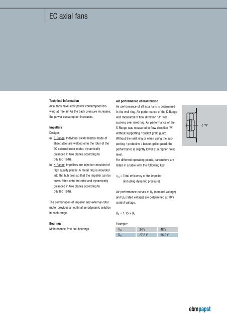
- Page 229 and 230: Air performance characteristic Air
- Page 231 and 232: 5,5 76 66 56 117,5 60,2 3 58 EC cen
- Page 233 and 234: 143 75 EC centrifugal AC axial AC c
- Page 235 and 236: 115 97 EC centrifugal AC axial AC c
- Page 237 and 238: 115 178 100 82 EC centrifugal AC ax
- Page 239 and 240: 59 171 87 EC centrifugal AC axial A
- Page 241 and 242: 120 105 130 115 94 92 6,6 226 103 E
- Page 243 and 244: - EMC: RFI immunity acc. to EN 6100
- Page 245 and 246: 130 115 227 101 EC centrifugal AC a
- Page 247 and 248: 130 115 227 103 EC centrifugal AC a
- Page 249 and 250: 129 285 123 EC centrifugal AC axial
- Page 251 and 252: 142,5 318 136 EC centrifugal AC axi
- Page 253 and 254: 142,5 317 148 EC centrifugal AC axi
- Page 255 and 256: 215 87 170,5 65,5 71 EC axial EC ce
- Page 257 and 258: EC centrifugal AC axial AC centrifu
- Page 259 and 260: EC centrifugal AC axial AC centrifu
- Page 261 and 262: 176 225 102 105 EC axial EC centrif
- Page 263 and 264: 123 285 5˚ 6x60˚ 1 Ø192 3,2 136
- Page 265 and 266: EC centrifugal AC axial AC centrifu
- Page 267 and 268: 148 317 5˚ 6x60˚ 1 Ø242 3,2 151
- Page 269: EC axial fans Axial fans Ø 200 -
- Page 273 and 274: • Wall ring unit N.B.: With full
- Page 275 and 276: Nominal data Type W1G250-HH37 -52 W
- Page 277 and 278: Selection Type *1G 200 Cable exit S
- Page 279 and 280: Selection Type *1G 250 Cable exit S
- Page 281 and 282: Selection Type *1G 300 c ±5 Brass
- Page 283 and 284: Selection Type *3G 400 600+20 85 8
- Page 285 and 286: Selection Type *3G 450 600+20 85 8
- Page 287 and 288: - Direction of rotation: dir. of ai
- Page 289 and 290: - Direction of rotation: dir. of ai
- Page 291 and 292: - Direction of rotation: dir. of ai
- Page 293 and 294: - Direction of rotation: dir. of ai
- Page 295 and 296: Selection Type *1G 250 6 85 450 +20
- Page 297 and 298: Selection Type *1G 300 Cable exit S
- Page 299 and 300: Selection Type *1G 350 Brass lead t
- Page 301 and 302: Selection Type *1G 360 85 Brass 6 l
- Page 303 and 304: Selection Type *1G 360 14 ±5 85 Br
- Page 305 and 306: EC-SYSTEMS Switch power supplies 31
- Page 307 and 308: External electronics CHW 050-AA01-7
- Page 309 and 310: PC with interface converter (RS485)
- Page 311 and 312: - Electrical connection: Line side:
- Page 313 and 314: - Electrical connection: Line side:
- Page 315 and 316: - Electrical connection: Line side:
- Page 317 and 318: - Electrical connection: Line side:
- Page 319 and 320: - Electrical connection: PE1 PE1 +
- Page 321 and 322:
- Electrical connection: Connector
- Page 323 and 324:
- Electrical connection: Connector
- Page 325 and 326:
- Electrical connection: PE1 PE2 RJ
- Page 327 and 328:
H- H- - Electrical connection: PE1
- Page 329 and 330:
- Electrical connection: 5 8 5 8 5
- Page 331 and 332:
Nominal data Type CBC 000-AB01 -01
- Page 333 and 334:
Nominal data Part no. 21487-1-0174
- Page 335 and 336:
Part no. 25711-2-0199 subject to al
- Page 337 and 338:
L1 H1 H2 N N N Alarm 1 Alarm 3 Alar
- Page 339 and 340:
Accessories Inlet rings 340 Guard g
- Page 341 and 342:
Accessories Øb f Øa r 106 c c 87
- Page 343 and 344:
Accessories 4,5 a c 2 d Part no. Si
- Page 345 and 346:
Accessories 133 13 31 Guard grilles
- Page 347 and 348:
Accessories h b g c Øe Øf Ød a G
- Page 349 and 350:
Accessories Ø87 max. 8 Ø58 2,8 g
- Page 351 and 352:
Accessories Ø162 Ø139 Ø154±1 4.
- Page 353 and 354:
Accessories d Part no. b 1,5 18918-
- Page 355 and 356:
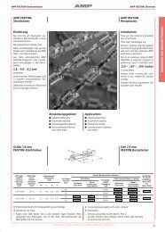
Accessories AMP-Universal-Mate-N-Lo
- Page 357 and 358:
Accessories d 10 b Ø a M8 Ø c 7±
- Page 359 and 360:
Accessories Ø50 M10 30 34 Anti-vib
- Page 361 and 362:
Europe Belgium Leuven VIBO Benelux
- Page 363:
Asia China Shanghai ebm Motor & Ven