
You also want an ePaper? Increase the reach of your titles
YUMPU automatically turns print PDFs into web optimized ePapers that Google loves.
CONNECTORS<br />
These include the sub-miniature DB-9/15,<br />
Micro D, Multiplex– 6 Pin, Molex KK Series<br />
0.156" Type, and the Dean Ultra Connector<br />
DB-9<br />
The DB-9 is the most popular connector.<br />
- Use a very small soldering iron tip, about<br />
1/16" = 0.063"<br />
- Tin servo wire<br />
- Cut tinned wires to a length that fits just to<br />
the bottom of the DB connector solder cup<br />
plus a fraction<br />
- Slip heat shrink over each tinned wire<br />
about 0.5" long, slip back as far from tinned<br />
end as possible to avoid shrinking during<br />
soldering<br />
- Mount DB connector in vise with cups<br />
pointed to the ceiling<br />
- Heat and fill each solder cup with solder, be<br />
sure to get good flow and fill the cup to just<br />
below the surface<br />
- Start on one end of connector and<br />
alternate between the two contact rows, for<br />
thee right-handed, start on left side<br />
- Clean solder iron tip, tin with a small<br />
amount of solder then while holding the<br />
tinned wire in one hand heat the solder<br />
in the cup to receive the wire. When the<br />
solder flows in the cup insert the tinned wire<br />
and hold until cool<br />
- After installation of all wires slip heat<br />
shrink down over each connection. Heat<br />
shrink is critical since even with this<br />
procedure some of the wire insulation will<br />
no doubt have melted back exposing bare<br />
lead which can be a source of a short.<br />
Some notes on using the DB-9 connector in<br />
sailplanes:<br />
In electronics, the DB connector will have<br />
a strain relief backshell to prevent wire<br />
breakage. In sailplanes this is not possible.<br />
After testing all electrical connections of the<br />
connector use some epoxy and thickener<br />
on the back of the connector for a strain<br />
relief. Be sure to use the thickener so that<br />
the epoxy does not run out to the sides - the<br />
opening for the DB connector is very tight.<br />
For the DB-9 connector you have 12 servo<br />
wires and only nine contacts. Standard<br />
convention is to use the female connector<br />
for the side of the circuit delivering power.<br />
Use the female connector for the fuselage<br />
and the male for the wing.<br />
This lack of a contact for each servo wire<br />
makes the DB-9 not the ideal connector<br />
for a full house wing but is very prevalent in<br />
sailplane models and easily acquired.<br />
I like to assign contacts 1,2,6,7 to one<br />
side of the wing, and 4,5,8,9 to the other<br />
(contact 3 is unused). Never try and install<br />
two wires into a single DB solder cup.<br />
Instead, solder a single wire to the cup<br />
about 1” long then solder the two power<br />
or ground leads to this wire and cover with<br />
heat shrink.<br />
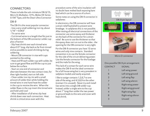
DB-9 pin layout<br />
Micro D connector<br />
One possible DB-9 pin arrangement:<br />
CONTACT SIGNAL<br />
1 Left wing power<br />
6 Left wing ground<br />
<br />
Left wing flap<br />
7 Left wing aileron<br />
5 Right wing power<br />
9 Right wing ground<br />
4 Right wing flap<br />
8 Right wing aileron<br />
3 Unused<br />
February <strong>2007</strong>