Development of a Component Head Injury Criteria (HIC ... - FAA
Development of a Component Head Injury Criteria (HIC ... - FAA
Development of a Component Head Injury Criteria (HIC ... - FAA

You also want an ePaper? Increase the reach of your titles
YUMPU automatically turns print PDFs into web optimized ePapers that Google loves.
Analyze ATD kinematics through<br />
biodynamic simulations<br />
(B)<br />
Analyze FSST data<br />
(A)<br />
Test and Evaluate<br />
Test and Evaluate the<br />
the NHCT<br />
<strong>Component</strong> Tester<br />
(G)<br />
Create biodynamic model<br />
and refine the design<br />
(C)<br />
Design the component<br />
<strong>HIC</strong> tester<br />
(D)<br />
Analytical Modeling<br />
(E)<br />
Fabricate <strong>Component</strong> <strong>HIC</strong><br />
Tester<br />
(F)<br />
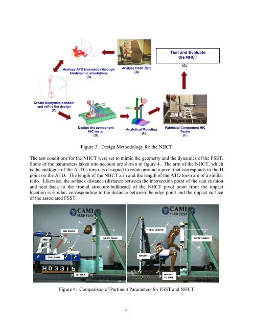
Figure 3. Design Methodology for the NHCT<br />
The test conditions for the NHCT were set to mimic the geometry and the dynamics <strong>of</strong> the FSST.<br />
Some <strong>of</strong> the parameters taken into account are shown in figure 4. The arm <strong>of</strong> the NHCT, which<br />
is the analogue <strong>of</strong> the ATD’s torso, is designed to rotate around a pivot that corresponds to the H<br />
point on the ATD. The length <strong>of</strong> the NHCT arm and the length <strong>of</strong> the ATD torso are <strong>of</strong> a similar<br />
ratio. Likewise, the setback distance (distance between the intersection point <strong>of</strong> the seat cushion<br />
and seat back to the frontal structure/bulkhead) <strong>of</strong> the NHCT pivot point from the impact<br />
location is similar, corresponding to the distance between the edge point and the impact surface<br />
<strong>of</strong> the associated FSST.<br />
Figure 4. Comparison <strong>of</strong> Pertinent Parameters for FSST and NHCT<br />
4