Development of a Component Head Injury Criteria (HIC ... - FAA
Development of a Component Head Injury Criteria (HIC ... - FAA
Development of a Component Head Injury Criteria (HIC ... - FAA

Create successful ePaper yourself
Turn your PDF publications into a flip-book with our unique Google optimized e-Paper software.
<strong>Head</strong> C.G Resultant Acceleration (g)<br />
140<br />
120<br />
100<br />
80<br />
60<br />
40<br />
20<br />
0<br />
<strong>Component</strong> <strong>HIC</strong><br />
test#01057-82<br />
Comp.<strong>HIC</strong>-Madymo<br />
5.4 Simulation<br />
1.78 1.8 1.82 1.84 1.86 1.88 1.9<br />
Time (sec)<br />
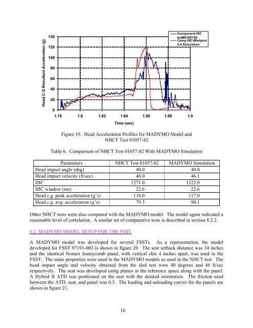
Figure 19. <strong>Head</strong> Acceleration Pr<strong>of</strong>iles for MADYMO Model and<br />
NHCT Test 01057-82<br />
Table 6. Comparison <strong>of</strong> NHCT Test 01057-82 With MADYMO Simulation<br />
Parameters NHCT Test 01057-82 MADYMO Simulation<br />
<strong>Head</strong> impact angle (deg) 40.0 40.0<br />
<strong>Head</strong> impact velocity (ft/sec) 46.0 46.1<br />
<strong>HIC</strong> 1271.0 1222.0<br />
<strong>HIC</strong> window (ms) 22.6 22.6<br />
<strong>Head</strong> c.g. peak acceleration (g’s) 110.0 117.0<br />
<strong>Head</strong> c.g. avg. acceleration (g’s) 79.3 90.1<br />
Other NHCT tests were also compared with the MADYMO model. The model again indicated a<br />
reasonable level <strong>of</strong> correlation. A similar set <strong>of</strong> comparative tests is described in section 8.2.2.<br />
6.2 MADYMO MODEL SETUP FOR THE FSST.<br />
A MADYMO model was developed for several FSSTs. As a representation, the model<br />
developed for FSST 97191-003 is shown in figure 20. The seat setback distance was 34 inches<br />
and the identical Nomex honeycomb panel, with vertical slits 4 inches apart, was used in the<br />
FSST. The same properties were used in the MADYMO models as used in the NHCT test. The<br />
head impact angle and velocity obtained from the sled test were 40 degrees and 46 ft/sec<br />
respectively. The seat was developed using planes in the reference space along with the panel.<br />
A Hybrid II ATD was positioned on the seat with the desired orientation. The friction used<br />
between the ATD, seat, and panel was 0.3. The loading and unloading curves for the panels are<br />
shown in figure 21.<br />
16