HP/Agilent 53131A 10 Digits/s Universal Counter
HP/Agilent 53131A 10 Digits/s Universal Counter
HP/Agilent 53131A 10 Digits/s Universal Counter

You also want an ePaper? Increase the reach of your titles
YUMPU automatically turns print PDFs into web optimized ePapers that Google loves.
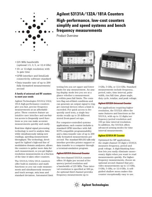
<strong>Agilent</strong> <strong>53131A</strong>/132A/181A <strong>Counter</strong>s<br />
High-performance, low-cost counters<br />
simplify and speed systems and bench<br />
frequency measurements<br />
Product Overview<br />
•225 MHz bandwidth<br />
(optional 1.5, 3, 5, or 12.4 GHz)<br />
•<strong>10</strong>- or 12-digit resolution with<br />
1sgate time<br />
•GPIB interface and IntuiLink<br />
connectivity software standard<br />
•Data transfer rate of up to 200<br />
fully formatted measurements/<br />
second<br />
A family of universal and RF counters<br />
to meet your needs<br />
<strong>Agilent</strong> Technologies <strong>53131A</strong>/132A/<br />
181A high-performance counters<br />
give you fast, precise frequency<br />
measurements at an affordable<br />
price. These counters feature an<br />
intuitive user interface and one-button<br />
access to frequently used functions<br />
so you can make accurate<br />
measurements quickly and easily.<br />
Real-time digital signal processing<br />
technology is used to analyze data<br />
while simultaneously taking new<br />
readings, speeding measurement<br />
throughput. The technology, developed<br />
for <strong>Agilent</strong>’s high-end line of<br />
modulation domain analyzers, allows<br />
the counters to gather more data for<br />
each measurement, so you get higherresolution<br />
measurements in a fraction<br />
of the time it takes other counters.<br />
The <strong>53131A</strong>/132A/181A counters<br />
offer built-in statistics and math<br />
functions so you can scale measurements<br />
and simultaneously measure<br />
and track average, min/max and<br />
standard deviation. Automated limit<br />
testing lets you set upper and lower<br />
limits for any measurement. An analog<br />
display mode lets you see at a<br />
glance whether a measurement<br />
is within pass/fail limits. The counters<br />
flag out-of-limit conditions and<br />
can generate an output signal to trigger<br />
external devices when a limit is<br />
exceeded. For quick access to frequently<br />
used tests, a single keystroke<br />
recalls up to 20 different<br />
stored front-panel set-ups.<br />
For computer-controlled systems<br />
applications, each counter includes a<br />
standard GPIB interface with full<br />
SCPI-compatible programmability<br />
and a data transfer rate of up to 200<br />
fully formatted measurements per<br />
second. The standard RS-232 talk-only<br />
interface provides printer support or<br />
data transfer to a computer through<br />
a terminal-emulation program.<br />
<strong>Agilent</strong> <strong>53131A</strong> <strong>Universal</strong> <strong>Counter</strong><br />
The two-channel <strong>53131A</strong> counter<br />
offers <strong>10</strong> digits per second of frequency/period<br />
resolution and<br />
a bandwidth of 225 MHz. Time interval<br />
resolution is specified at 500 ps.<br />
An optional third channel provides<br />
frequency measurements up to<br />
3 GHz, 5 GHz, or 12.4 GHz. Standard<br />
measurements include frequency,<br />
period, ratio, time interval, pulse<br />
width, rise/fall time, phase angle,<br />
duty cycle, totalize, and peak voltage.<br />
<strong>Agilent</strong> 53132A <strong>Universal</strong> <strong>Counter</strong><br />
For applications requiring higher<br />
resolution, the 53132A offers the<br />
same features and functions as the<br />
<strong>53131A</strong>, with up to 12 digits/sec<br />
frquency/period resolution and<br />
150 ps time interval resolution.<br />
In addition, the 53132A offers<br />
advanced arming modes for time<br />
interval measurements.<br />
<strong>Agilent</strong> 53181A RF <strong>Counter</strong><br />
Optimized for RF applications,<br />
the single-channel <strong>10</strong> digit/s 53181A<br />
measures frequency, period and<br />
peak voltage. A digit-blanking function<br />
lets you easily eliminate unnecessary<br />
digits when you want to read<br />
measurements quickly. For higherfrequency<br />
measurements, choose an<br />
optional second channel that provides<br />
measurements up to 1.5 GHz,<br />
3 GHz, 5 GHz, or 12.4 GHz. A selfguided<br />
shallow menu makes this<br />
counter exceptionally easy to use.<br />
<strong>Agilent</strong> Technologies
<strong>Agilent</strong> IntuiLink provides easy access<br />
to the counter’s data from your PC<br />
The <strong>Agilent</strong> <strong>53131A</strong>/132A/181A<br />
counters capture precise frequency<br />
and time measurements. IntuiLink<br />
software allows that data to be put<br />
to work easily. You work in a familiar<br />
environment at all times, using<br />
PC applications such as Microsoft<br />
Excel® or Word® to analyze, interpret,<br />
display, print, and document<br />
the data you get from the counter.<br />
Also available is BenchLink Meter<br />
software, a standalone application.<br />
It gives you the flexibility to configure<br />
and run tests from your PC,<br />
making data gathering more convenient.<br />
BenchLink Meter lets you:<br />
•configure tests, including measurement<br />
type, number of readings,<br />
measurement speed, and more.<br />
•choose display modes from<br />
real-time strip chart, histogram,<br />
readout, and table mode.<br />
•scale measurements data.<br />
•copy captured data to other programs.<br />
Optional timebases offer<br />
increased stability<br />
Optional timebases are available<br />
for <strong>53131A</strong>/132A/181A counters<br />
to increase measurement accuracy.<br />
Option 0<strong>10</strong> provides a high stability<br />
oven timebase with aging of less<br />
than 5 x <strong>10</strong> -<strong>10</strong> per day.<br />
Microsft Excel and Word are US registered trademarks<br />
of Microsoft Corporation.<br />
Time Base<br />
Internal Time Base Stability (see graph 3 for timebase contribution of measurement error)<br />
Standard Medium Oven High Oven Ultra High Oven<br />
(0° to 50° C) (Option 001) (Option 0<strong>10</strong>) (Option 012 for 53132A only)<br />
Temperature Stability (referenced to 25°C) < 5 x <strong>10</strong> -6 < 2 x <strong>10</strong> -7 < 2.5 x <strong>10</strong> -9 < 2.5 x <strong>10</strong> -9<br />
Aging Rate Per Day: < 4 x <strong>10</strong> -8 < 5 x <strong>10</strong> -<strong>10</strong> < 1 x <strong>10</strong> -<strong>10</strong><br />
(after 30 days) Per Month: < 3 x <strong>10</strong> -7 < 2 x <strong>10</strong> -7 < 1.5 x <strong>10</strong> -8 < 3 x <strong>10</strong> -9<br />
Per Year: < 2 x <strong>10</strong> -8<br />
Turn-on stability vs. time<br />
(in 30 minutes) < 2 x <strong>10</strong> -7 < 5 x <strong>10</strong> -9 < 5 x <strong>10</strong> -9<br />
referenced to 2 Hr referenced to 24 Hr referenced to 24 Hr<br />
Calibration Manual Adjust Electronic Electronic Electronic<br />
Note that power to the time base is maintained when the counter is placed in standby via the front panel switch. The internal fan will continue to operate<br />
when in standby to maintain long-term measurement reliability.<br />
Instrument Inputs<br />
Input Specifications<br />
Channel 1 & 2 (<strong>53131A</strong>, 53132A) 1<br />
Channel 1 (53181A)<br />
Frequency Range<br />
dc Coupled<br />
dc to 225 MHz<br />
ac Coupled 1 MHz to 225 MHz (50 Ω)<br />
30 Hz to 225 MHz (1 MΩ)<br />
FM Tolerance 25%<br />
Voltage Range and Sensitivity (Sinusoid) 2<br />
dc to <strong>10</strong>0 MHz 20 mVrms to ±5 V ac + dc<br />
<strong>10</strong>0 MHz to 200 MHz 30 mVrms to ±5 V ac + dc<br />
200 MHz to 225 MHz 40 mVrms to ±5 V ac + dc<br />
(all specified at 75 mVrms<br />
with opt. rear connectors) 3<br />
2<br />
Voltage Range and Sensitivity<br />
(Single-Shot Pulse) 2<br />
4.5 ns to <strong>10</strong> ns<br />
Pulse Width <strong>10</strong>0 mVpp to <strong>10</strong> Vpp<br />
(150 mVpp with optional<br />
rear connectors) 3<br />
><strong>10</strong> ns Pulse Width 50 mVpp to <strong>10</strong> Vpp<br />
(<strong>10</strong>0 mVpp with optional<br />
rear connectors) 3<br />
Trigger Level 2<br />
Range<br />
Accuracy<br />
Resolution<br />
Damage Level<br />
± 5.125 V<br />
± (15 mV + 1% of trigger<br />
level)<br />
5 mV<br />
50 Ω 5 Vrms<br />
0 to 3.5 kHz, 1 MΩ 350 Vdc + ac pk<br />
3.5 kHz to <strong>10</strong>0 kHz,<br />
1 MΩ 350 Vdc + ac pk linearly<br />
derated to 5 Vrms<br />
><strong>10</strong>0 kHz, 1 MΩ 5 Vrms<br />
Input Characteristics<br />
Channel 1 & 2 (<strong>53131A</strong>, 53132A) 1<br />
Channel 1 (53181A)<br />
Impedance<br />
1MΩ or 50Ω<br />
1 MΩ Capacitance 30 pF<br />
Coupling<br />
ac or dc<br />
Low-Pass Filter <strong>10</strong>0 kHz, switchable<br />
-20 dB at > 1 MHz<br />
Input Sensitivity Selectable between Low,<br />
Medium, or High (default).<br />
Low is approximately 2x<br />
High Sensitivity.<br />
1. Specifications and Characteristics for Channels 1 and<br />
2 are identical for both common and separate configurations.<br />
2. Values shown are for X1 attenuator setting. Multiply<br />
all values by <strong>10</strong> (nominal) when using the X<strong>10</strong> attenuator<br />
setting.<br />
3. When the <strong>53131A</strong> or 53132A are ordered with the<br />
optional rear terminals (Opt. 060), the channel 1 and<br />
2 inputs are active on both front and rear of the<br />
counter. When the 53181A is ordered with the<br />
optional rear terminal, the channel 1 input is active<br />
on both front and rear of the counter. For this condition,<br />
specifications indicated for the rear connections<br />
also apply to the front connections.
Trigger Slope<br />
Auto Trigger Level<br />
Range<br />
Frequency<br />
Input Amplitude<br />
Attenuator<br />
Voltage Range<br />
Trigger Range<br />
Positive or Negative<br />
0 to <strong>10</strong>0% in <strong>10</strong>% steps<br />
> <strong>10</strong>0 Hz<br />
> <strong>10</strong>0 mVpp<br />
(No amplitude modulation)<br />
x<strong>10</strong><br />
x<strong>10</strong><br />
Input Specifications 4<br />
Channel 3 (<strong>53131A</strong>, 53132A)<br />
Channel 2 (53181A)<br />
Frequency Range<br />
Option 015<br />
(for 53181A only)<br />
Option 030<br />
Option 050<br />
Option 124<br />
<strong>10</strong>0 MHz to 1.5 GHz<br />
(see Opt. 030 for additional<br />
specs)<br />
<strong>10</strong>0 MHz to 3 GHz<br />
200 MHz to 5 GHz<br />
200 MHz to 12.4 GHz<br />
Power Range and Sensitivity (Sinusoid)<br />
Option 030<br />
Option 050<br />
Option 124<br />
<strong>10</strong>0 MHz to 2.7 GHz:<br />
-27 dBm to +19 dBm<br />
2.7 GHz to 3 GHz:<br />
-21 dBm to +13 dBm<br />
200 MHz to 5 GHz:<br />
-23 dBm to +13 dBm<br />
200 MHz to 12.4 GHz<br />
-23 dBm to +13 dBm<br />
4. When optional additional channels are ordered with<br />
Opt. 060, refer to configuration table for Opt. 060<br />
under ordering info on page 8. There is no degradation<br />
in specifications for this input, as applicable.<br />
Damage Level<br />
Option 030<br />
Option 050<br />
Option 124<br />
Characteristics<br />
5 Vrms<br />
+25 dBm<br />
+25 dBm<br />
Impedance<br />
50 Ω<br />
Coupling<br />
AC<br />
VSWR 50 ns<br />
< 250 ns<br />
> 50 ns<br />
<strong>10</strong> Vrms<br />
External Arm Input Characteristics 5<br />
Impedance<br />
1 kΩ<br />
Input Capacitance 17 pF<br />
Start/Stop Slope Positive or Negative<br />
External Time Base Input Specifications<br />
Voltage Range 200 mVrms to <strong>10</strong> Vrms<br />
Damage Level <strong>10</strong> Vrms<br />
Frequency<br />
1 MHz, 5 MHz, and<br />
<strong>10</strong> MHz<br />
(53132A <strong>10</strong> MHz only)<br />
Time Base Output Specifications<br />
Output Frequency <strong>10</strong> MHz<br />
Voltage<br />
> 1 Vpp into 50 Ω<br />
(centered around 0 V)<br />
Measurement Specifications<br />
Frequency (<strong>53131A</strong>, 53132A, 53181A)<br />
Channel 1 and 2 (53131, 53132); Channel 1 (53181)<br />
Range<br />
0.1 Hz to 225 MHz<br />
Channel 3 (<strong>53131A</strong>, 53132A) Channel 2 (53181A)<br />
Option 015 (53181only) <strong>10</strong>0 MHz to 1.5 GHz<br />
Option 030<br />
<strong>10</strong>0 MHz to 3 GHz<br />
Option 050<br />
200 MHz to 5 GHz<br />
Option 124<br />
200 MHz to 12.4 GHz<br />
(Period 2 or 3 selectable via GPIB only)<br />
Period (53131, 53132, 53181)<br />
Channel 1 and 2 (53131, 53132); Channel 1 (53181)<br />
Range<br />
4.44 ns to <strong>10</strong> s<br />
Channel 3 (<strong>53131A</strong>, 53132A); Channel 2 (53181A)<br />
Option 015 (53181 only) 0.66 ns to <strong>10</strong> ns<br />
Option 030<br />
0.33 ns to <strong>10</strong> ns<br />
Option 050<br />
0.2 ns to 5 ns<br />
Option 124<br />
80 ps to 5 ns<br />
Frequency Ratio (53131, 53132, 53181)<br />
Measurement is specified over the full signal<br />
range of each input.<br />
Results Range <strong>10</strong> -<strong>10</strong> to <strong>10</strong> 11<br />
“Auto” Gate Time<br />
<strong>10</strong>0 ms<br />
5. Available for all measurements except Peak Volts.<br />
External Arm is referred to as External Gate for some<br />
measurements.<br />
For Automatic or External Arming:<br />
(and signals < <strong>10</strong>0 Hz using Timed Arming)<br />
LSD Displayed:<br />
RMS Resolution:<br />
t res<br />
Gate Time<br />
Frequency<br />
or<br />
Period<br />
t 2 res 2 Trigger Error 2 <br />
Gate Time<br />
<strong>53131A</strong> t res 53132A t res 53181A t res<br />
typical 650 ps 200 ps 650 ps<br />
see graphs for worst case resolution performance<br />
For Automatic Arming: Gate Time =<br />
N<br />
Frequency<br />
where N = 1 for standard channel Frequency < 1 MHz<br />
4 for standard channel Frequency > 1 MHz<br />
128 for optional channel<br />
Systematic Uncertainty:<br />
<strong>53131A</strong> t acc<br />
350 ps<br />
± Time Base Error ±<br />
53132A t acc<br />
<strong>10</strong>0 ps<br />
typical<br />
worst case<br />
1.25 ns 500 ps<br />
Trigger: Default setting is Auto Trigger at 50%<br />
Frequency<br />
or<br />
Period<br />
t acc<br />
Gate Time<br />
53181A t acc<br />
350 ps<br />
1.25 ns<br />
Frequency<br />
or<br />
Period<br />
For Time or <strong>Digits</strong> Arming:<br />
LSD Displayed:<br />
RMS Resolution<br />
(see graph 2):<br />
t res<br />
Systematic Uncertainty:<br />
4 t 2 res (2 Trigger Error 2 )<br />
<br />
Gate Time Number of Samples Gate Time<br />
t jitter<br />
t res<br />
typical 500 ps 50 ps 225 ps<br />
see graphs for worst case resolution performance<br />
<strong>53131A</strong>/181A<br />
t acc<br />
typical <strong>10</strong>0 ps<br />
worst case 300 ps<br />
2 2 t res t jitter<br />
<br />
Frequency<br />
or<br />
Gate Time Number of Samples Gate Time Period<br />
<strong>53131A</strong>/181A<br />
± Time Base Error ±<br />
53132A<br />
t acc<br />
<strong>10</strong> ps<br />
<strong>10</strong>0 ps<br />
Trigger: Default setting is Auto Trigger at 50%<br />
53132A<br />
t jitter<br />
3 ps<br />
t acc<br />
Gate Time<br />
t jitter<br />
Number of Samples = Gate Time x Frequency (Frequency < 200 kHz)<br />
Gate Time x 200,000 (Frequency > 200 kHz)<br />
Frequency<br />
or<br />
Period<br />
Frequency<br />
or<br />
Period<br />
3
Time Interval (<strong>53131A</strong>, 53132A)<br />
Measurement is specified over the full signal<br />
ranges 6 of Channels 1 and 2.<br />
Results Range<br />
-1 ns to <strong>10</strong> 5 s<br />
LSD 500 ps (53131)/<br />
150 ps (53132)<br />
Phase (<strong>53131A</strong>, 53132A)<br />
Measurement is specified over the full signal<br />
range of Channels 1 and 2.<br />
Results Range -180° to +360°<br />
Duty Cycle (<strong>53131A</strong>, 53132A)<br />
Measurement is specified over the full signal<br />
range of Channel 1. However, both the positive<br />
and negative pulse widths must be greater than<br />
4 ns.<br />
Results Range<br />
0 to 1 (e.g. 50% duty cycle<br />
would be displayed as .5)<br />
6. See Specifications for Pulse Width and Rise/Fall<br />
Time measurements for additional restrictions on signal<br />
timing characteristics<br />
Rise/Fall Time (<strong>53131A</strong>, 53132A)<br />
Measurement is specified over the full signal<br />
ranges of Channel 1. The interval between the<br />
end of one edge and start of a similar edge must<br />
be greater than 4 ns.<br />
Edge Selection<br />
Trigger<br />
Results Range<br />
LSD<br />
Positive or Negative<br />
Default setting is Auto<br />
Trigger at <strong>10</strong>% and 90%<br />
5 ns to <strong>10</strong> 5 s<br />
500 ps (53131)/150 ps<br />
(53132)<br />
Pulse Width (<strong>53131A</strong>, 53132A)<br />
Measurement is specified over the full signal<br />
range of Channel 1. The width of the opposing<br />
pulse must be greater than 4 ns.<br />
Pulse Selection<br />
Trigger<br />
Results Range<br />
Positive or Negative<br />
Default setting is Auto<br />
Trigger at 50%<br />
5 ns to <strong>10</strong> 5 s<br />
Totalize (<strong>53131A</strong>, 53132A)<br />
Measurement is specified over the full signal<br />
range of Channel 1.<br />
Results Range 0 to <strong>10</strong> 15<br />
Resolution<br />
± 1 count<br />
Peak Volts (<strong>53131A</strong>, 53132A, 53181A)<br />
Measurement is specified on Channels 1 and 2<br />
for dc signals; or for ac signals of frequencies<br />
between <strong>10</strong>0 Hz and 30 MHz with peak-to-peak<br />
amplitude greater than <strong>10</strong>0 mV.<br />
Results Range<br />
Resolution<br />
-5.1 V to +5.1 V<br />
<strong>10</strong> mV<br />
Peak Volts Systematic Uncertainty<br />
for ac signals: 25 mV + <strong>10</strong>% of V<br />
for dc signals: 25 mV + 2% of V<br />
Use of the input attenuator multiplies all voltage<br />
specifications (input range, results range, resolution<br />
and systematic uncertainty) by a nominal<br />
factor of <strong>10</strong>.<br />
LSD<br />
500 ps (53131)/150 ps<br />
(53132)<br />
Time Interval, Pulse Width, Rise/Fall Time (53131 and 53132 only):<br />
RMS Resolution:<br />
(t res ) 2 Start Trigger Error 2 Stop Trigger Error 2<br />
Systematic Uncertainty:<br />
± (Time Base Error Measurement) ± Trigger Level Timing Error ± 1.5 ns Differential Channel Error (<strong>53131A</strong>)<br />
± (Time Base Error Measurement) ± Trigger Level Timing Error ± 900 ps Differential Channel Error (53132A)<br />
where t res = 750 ps for the <strong>53131A</strong>, 300 ps for the 53132A<br />
Ch1<br />
Frequency Ratio: , Ch1 , Ch2 , Ch3<br />
Ch1 , Ch2<br />
(<strong>53131A</strong> and 53132A) (53181A)<br />
Ch2 Ch3 Ch1 Ch1<br />
Ch2 Ch1<br />
1<br />
1<br />
LSD: Ratio :<br />
2 Ch2 Freq Gate Time<br />
2 Ch2 Freq<br />
Ratio :<br />
1 (Ch1 Freq) 2 Gate Time<br />
RMS Resolution:<br />
1<br />
Ratio :<br />
2 1 (Ch1 Freq Ch2 Trigger Error) 2<br />
2<br />
Ch2 Freq Gate Time<br />
2 2 Ch2 Freq 1 (Ch1 Freq Ch2 Trigger Error)<br />
Ratio :<br />
2<br />
1<br />
(Ch1 Freq) 2 Gate Time<br />
For measurements using Ch3, substitute Ch3 for Ch2 in these equations.<br />
To minimize relative phase measurement error, connect the<br />
higher frequency signal to channel 1.<br />
Systematic Uncertainty: ± 2x resolution<br />
Phase (53131 and 53132)<br />
RMS Resolution:<br />
Phase<br />
t res 2 2 Trigger Error 2 1 <br />
Frequency 360 °<br />
360 °<br />
2<br />
Systematic Uncertainty:<br />
( ± Trigger Level Timing Error ± 1.5 ns Differential Channel Error) Frequency 360 ° (53131)<br />
( ± Trigger Level Timing Error ± 900 ps Differential Channel Error) Frequency 360 ° (53132)<br />
Duty Cycle (53131 and 53132)<br />
RMS Resolution:<br />
((T res ) 2 (2 x Trigger Error 2 )) ( 1 Duty Cycle 2 ) Frequency<br />
4<br />
t res<br />
<strong>53131A</strong><br />
750 ps<br />
53132A<br />
300 ps
Gate Time<br />
Auto Mode, or 1 ms to<br />
<strong>10</strong>00 s<br />
Measurement Throughput<br />
GPIB ASCII<br />
200 measurements/s<br />
(maximum)<br />
Measurement Arming<br />
Start Measurement Free Run, Manual, or<br />
External<br />
Stop Measurement<br />
Time Interval<br />
Delayed Arming<br />
Continuous, Single,<br />
External, or Timed<br />
<strong>10</strong>0 µs to <strong>10</strong> s (<strong>53131A</strong>)<br />
<strong>10</strong>0 ns to <strong>10</strong> s (53132A)<br />
Arming Modes<br />
(Note that not all arming modes are available for<br />
every measurement function.)<br />
Auto Arming: Measurements are initiated immediately<br />
and acquired as fast as possible, using a<br />
minimum number of signal edges.<br />
Timed Arming: The duration of the measurement<br />
is internally timed to a user-specified value (also<br />
known as the “gate time”).<br />
<strong>Digits</strong> Arming: Measurements are performed<br />
to the requested resolution (number of digits)<br />
through automatic selection of the acquisition<br />
time.<br />
External Arming: An edge on the External Arm<br />
Input enables the start of each measurement.<br />
Auto Arming, Timed arming modes or another<br />
edge on the External Arm Input may be used to<br />
complete the measurement.<br />
Time Interval Delayed Arming: For Time Interval<br />
measurements, the Stop Trigger condition is<br />
inhibited for a user-specified time following the<br />
Start Trigger. The 53132A offers advanced time<br />
interval arming capabilities including use of user<br />
specified time or Channel 2 events to delay both<br />
Start and Stop Triggers.<br />
Measurement Limits<br />
Limit Checking: The measurement value is<br />
checked against user-specified limits at the end<br />
of each measurement.<br />
Display Modes: The measurement result may be<br />
displayed as either the traditional numeric value<br />
or graphically as an asterisk moving between two<br />
vertical bars.<br />
Out-of-Limits Indications:<br />
• The limits annunciator will light on the front<br />
panel display.<br />
• The instrument will generate an SRQ if enabled<br />
via GPIB.<br />
• The limits hardware signal provided via the RS-<br />
232 connector will go low for the duration of<br />
the out-of-limit condition.<br />
• If the Analog Display mode is enabled, the<br />
asterisk appears outside the vertical bars,<br />
which define the upper and lower limits.<br />
Fractional Time Base Error (see graph 3)<br />
Time base error is the maximum fractional frequency variation of the time base due to aging or fluctuations in ambient temperature or line voltage:<br />
∆f ∆f ∆f<br />
Time Base Error =<br />
( ------- f aging rate + ------- f )<br />
temperature + ------ f<br />
line voltage<br />
Multiply this quantity by the measurement result to yield the absolute error for that measurement. Averaging measurements will not reduce (fractional) time<br />
base error. The counters exhibit negligible sensitivity to line voltage; consequently the line voltage term may be ignored.<br />
Trigger Error<br />
External source and input amplifier noise may advance or delay the trigger points that define the beginning and end of a measurement. The resulting timing<br />
uncertainty is a function of the slew rate of the signal and the amplitude of spurious noise spikes (relative to the input hysteresis band). The (rms) trigger<br />
error associated with a single trigger point is:<br />
E input 2 E signal 2<br />
Trigger Error in seconds<br />
Input Signal Slew Rate at Trigger Point<br />
where<br />
E input = RMS noise of the input amplifier: 1 mVrms (350µVrms Typical). Note that the internal measurement algorithms significantly reduce the contribution<br />
of this term.<br />
E signal = RMS noise of the input signal over a 225 MHz bandwidth (<strong>10</strong>0 kHz bandwidth when the low-pass filter is enabled). Note that the filter may substantially<br />
degrade the signal’s slew rate at the input of the trigger comparator.<br />
For two-trigger-point measurements (e.g. Rise Time, Pulse Width), the Trigger Errors will be referred to independently as Start Trigger Error and Stop Trigger<br />
Error.<br />
Trigger Level Timing Error (see graph 6)<br />
Trigger level timing error results from a deviation of the actual trigger level from the specified level. The magnitude of this error depends on resolution and<br />
accuracy of the trigger level circuit, input amplifier fidelity, input signal slew rate, and width of the input hysteresis band.<br />
The following equations should be summed together to obtain the overall Trigger Level Timing Error. At the "High" sensitivity input setting, the hysteresis<br />
band can be assumed to be the sensitivity of the counter input (see page 2). Reduction of input sensitivity or use of the attenuator will increase the size of<br />
this band.<br />
Input Hysteresis Error:<br />
0.5 x Hysteresis Band<br />
Input Signal Slew Rate at Start Trigger Point –<br />
0.5 x Hysteresis Band<br />
Input Signal Slew Rate at Stop Trigger Point<br />
15 mV±(1% x Start Trigger Level Setting) 15 mV±(1% x Stop Trigger Level Setting)<br />
Trigger Level Setting Error: ± Input Signal Slew Rate at Start Trigger Point ± Input Signal Slew Rate at Stop Trigger Point<br />
Differential Channel Error<br />
The differential channel error term stated in several Systematic Uncertainty equations accounts for channel-to-channel mismatch and internal noise. This<br />
error can be substantially reduced by performing a TI calibration (accessible via the Utility Menu) in the temperature environment in which future measurements<br />
will be made.<br />
5
Graph 1:<br />
<strong>Agilent</strong> <strong>53131A</strong>/181A–Worst Case RMS<br />
Resolution 7<br />
(Automatic or External Arming)<br />
The graphs may also be used to compute errors<br />
for Period Measurements. To find the Period error<br />
(DP), calculate the frequency of the input signal<br />
(F = 1/P) and find the frequency error (DF) from<br />
the chart.<br />
Then calculate the period error as:<br />
∆P<br />
=<br />
∆F<br />
F<br />
P<br />
Frequency Error (Hz)<br />
1E + 02<br />
1E + 00<br />
1E – 02<br />
Auto Armed<br />
1E – 04<br />
1 ms<br />
1E – 06<br />
<strong>10</strong> ms Gate<br />
<strong>10</strong>0 ms Time<br />
1E – 08<br />
1 s<br />
<strong>10</strong>s<br />
1E – <strong>10</strong><br />
<strong>10</strong><br />
<strong>10</strong>0<br />
<strong>10</strong>00 1E + 05 1E + 07 1E + 09<br />
<strong>10</strong>000 1E + 06 1E + 08 1E + <strong>10</strong><br />
Input Frequency (Hz)<br />
Graph 2:<br />
<strong>Agilent</strong> <strong>53131A</strong>/181A–Worst Case RMS<br />
Resolution 7<br />
(Time or <strong>Digits</strong> Arming)<br />
Frequency Error (Hz)<br />
E + 02<br />
1E + 00<br />
1E – 02<br />
1E – 04<br />
1E – 06<br />
1E – 08<br />
1E – <strong>10</strong><br />
<strong>10</strong> s<br />
<strong>10</strong><br />
<strong>10</strong>0<br />
<strong>10</strong>00 1E + 05 1E + 07 1E + 09<br />
<strong>10</strong>000 1E + 06 1E + 08 1E + <strong>10</strong><br />
Input Frequency (Hz)<br />
1 s<br />
<strong>10</strong>0 ms<br />
<strong>10</strong> ms<br />
1 ms<br />
Gate<br />
Time<br />
Graph 3:<br />
Timebase Error<br />
7. Graphs 1, 2, 4 and 5 do not reflect the effects of<br />
trigger error. To place an upper bound on the added<br />
effect of this error term, determine the frequency<br />
error from the appropriate graph and add a trigger<br />
error term as follows:<br />
Time or Digit Arming<br />
Frequency Error +<br />
Automatic or External Arming<br />
Frequency Error +<br />
4 2 Trigger Error<br />
Gate Time Number of Samples<br />
2 Trigger Error<br />
Gate Time<br />
Frequency<br />
or<br />
Period<br />
Frequency<br />
or<br />
Period<br />
Frequency Error<br />
<strong>10</strong> kHz<br />
1 kHz<br />
<strong>10</strong>0 Hz<br />
<strong>10</strong> Hz<br />
1 Hz<br />
<strong>10</strong>0 mHz<br />
<strong>10</strong> mHz<br />
1 mHz<br />
<strong>10</strong>0 µHz<br />
<strong>10</strong>µHz<br />
1 µHz<br />
<strong>10</strong>0 nHz<br />
<strong>10</strong> nHz<br />
High Stability T.B.<br />
<strong>10</strong> years after cal<br />
Standard T.B.<br />
1 year after cal<br />
Medium T.B.<br />
1 year after cal<br />
High Stability T.B.<br />
1 month after cal<br />
High Stability T.B.<br />
1 year after cal<br />
Ultra Stability T.B.<br />
1 year after cal<br />
Standard T.B.<br />
1 month after cal<br />
Medium T.B.<br />
1 month after cal<br />
<strong>10</strong> Hz 1 kHz <strong>10</strong>0 kHz <strong>10</strong> MHz 1 GHz<br />
1 Hz <strong>10</strong>0 Hz <strong>10</strong> kHz 1 MHz <strong>10</strong>0 MHz<br />
<strong>10</strong> ns 1 µs <strong>10</strong>0 µs <strong>10</strong> ms 1 sec<br />
1 ns <strong>10</strong>0 ns <strong>10</strong> µs 1 ms <strong>10</strong>0 ms<br />
Input Signal Frequency or Time<br />
<strong>10</strong> µs<br />
1 µs<br />
<strong>10</strong>0 ns<br />
<strong>10</strong> ns<br />
1 ns<br />
<strong>10</strong>0 ps<br />
<strong>10</strong> ps<br />
1 ps<br />
<strong>10</strong>0 fs<br />
<strong>10</strong> fs<br />
1 fs<br />
<strong>10</strong>0 as<br />
<strong>10</strong> as<br />
Time Error<br />
6
Graph 4: <strong>Agilent</strong> 53132A–Worst Case RMS Resolution 7<br />
(Automatic or External Arming)<br />
1E + 02<br />
Auto Armed<br />
1E + 00<br />
Frequency Error (Hz) Frequency Error (Hz)<br />
1E – 02<br />
1E – 04<br />
1E – 06<br />
1E – 08<br />
1E – <strong>10</strong><br />
<strong>10</strong> <strong>10</strong>00 1E + 05 1E + 07 1E + 09<br />
<strong>10</strong>0 <strong>10</strong>000 1E + 06 1E + 08 1E + <strong>10</strong><br />
Input Frequency (Hz)<br />
Graph 5: <strong>Agilent</strong> 53132A–Worst Case RMS Resolution 7<br />
(Time or <strong>Digits</strong> Arming)<br />
E + 02<br />
1 ms<br />
1E + 00<br />
1E – 02<br />
1E – 04<br />
1E – 06<br />
1E – 08<br />
1E – <strong>10</strong><br />
<strong>10</strong>s<br />
1 ms<br />
<strong>10</strong> ms Gate<br />
<strong>10</strong>0 ms Time<br />
<strong>10</strong> <strong>10</strong>00 1E + 05 1E + 07 1E + 09<br />
<strong>10</strong>0 <strong>10</strong>000 1E + 06 1E + 08 1E + <strong>10</strong><br />
Input Frequency (Hz)<br />
Graph 6: Trigger Level Timing Error<br />
(Level Setting Error and Input Hysteresis)<br />
<strong>10</strong>0 µs<br />
200 to 225 MHz Rep. Rate<br />
Trigger Error per Trigger Point<br />
<strong>10</strong> µs<br />
1 µs<br />
<strong>10</strong>0 ns<br />
<strong>10</strong> s<br />
<strong>10</strong> ns<br />
Pulse and T.I. at 5V trigger point<br />
1 ns<br />
Pulse and T.I. at 2.5V trigger point<br />
<strong>10</strong>0 ps<br />
Pulse and T.I. at 0V trigger point<br />
<strong>10</strong> ps<br />
1V/ms <strong>10</strong>0mV/µs <strong>10</strong>mV/ns 1V/ns<br />
<strong>10</strong>mV/µs 1V/µs <strong>10</strong>0mV/ns <strong>10</strong>mV/ps<br />
Input Signal Slew Rate at Trigger Point<br />
1 s<br />
1 s<br />
<strong>10</strong>0 ms<br />
<strong>10</strong>0 to 200 MHz Rep. Rate<br />
<strong>10</strong> ms<br />
dc to <strong>10</strong>0 MHz Rep. Rate<br />
Gate<br />
Time<br />
Measurement Statistics<br />
Available Statistics Mean, Minimum,<br />
Maximum, Standard<br />
Deviation<br />
Number of 2 to 1,000,000.<br />
Measurements Statistics may be collected<br />
on all measurements or<br />
on only those which are<br />
between the limit bands.<br />
When the Limits function<br />
is used in conjunction<br />
with Statistics, N (number<br />
of measurements) refers<br />
to the number of in-limit<br />
measurements. In general,<br />
measurement resolution<br />
will improve in proportion<br />
to N , up to the numerical<br />
processing limits of the<br />
instrument.<br />
Measurements Statistics may be collected<br />
for all measurements<br />
except Peak Volts and<br />
Totalize.<br />
General Information<br />
Save and Recall<br />
Up to 20 complete instrument setups may be<br />
saved and recalled later. These setups are<br />
retained when power is removed from the counter.<br />
Rack Dimensions 88.5 mm x 212.6 mm x<br />
(HxWxD)<br />
348.3 mm<br />
Weight<br />
3.5 kg maximum<br />
Warranty<br />
1 year<br />
Power Supply <strong>10</strong>0 to 120 VAC ± <strong>10</strong>% -50,<br />
60 or 400 Hz ± <strong>10</strong>% 220<br />
to 240 VAC ± <strong>10</strong>% -50<br />
or 60 Hz ± <strong>10</strong>%<br />
ac Line Selection Automatic<br />
Power Requirements 170 VA maximum<br />
(30 W typical)<br />
Environment 0° C to 55° C operating<br />
–40° C to 71° C storage<br />
Remote Interface GPIB (IEEE 488.1-1987,<br />
IEEE 488.2-1987)<br />
Remote<br />
SCPI-1992.0<br />
Programming (Standard Commands<br />
Language<br />
for Programmable<br />
Instruments)<br />
Safety<br />
Designed in compliance<br />
with IEC-<strong>10</strong><strong>10</strong>, UL-3111-1<br />
(draft), CAN/CSA <strong>10</strong><strong>10</strong>.1<br />
EMC<br />
CISPR-11, EN50082-1,<br />
IEC 801-2, -3, -4<br />
Radiated Immunity When the product is<br />
Testing<br />
operated at maximum<br />
sensitivity (20 mVrms)<br />
and tested at 3 V/m<br />
according to IEC 801-3,<br />
external <strong>10</strong>0 to 200 MHz<br />
electric fields may cause<br />
frequency miscounts.<br />
7
Ordering Information<br />
<strong>53131A</strong> <strong>10</strong> digit/s, 500 ps <strong>Universal</strong> <strong>Counter</strong><br />
53132A 12 digit/s, 150 ps <strong>Universal</strong> <strong>Counter</strong><br />
53181A <strong>10</strong>-digit/s RF <strong>Counter</strong><br />
Accessories Included<br />
Each counter comes with IntuiLink software,<br />
standard timebase, power cord, operating,<br />
programming and service manuals.<br />
Manual Options (please specify one<br />
when ordering)<br />
ABA US English<br />
ABD German<br />
ABE Spanish<br />
ABF French<br />
ABJ Japanese<br />
ABZ Italian<br />
ABO Taiwan Chinese<br />
AB1 Korean<br />
AB2 Chinese<br />
Other Options<br />
Opt. 001 Medium-stability timebase<br />
Opt. 0<strong>10</strong> High-stability timebase<br />
Opt. 012 Ultra-High stability timebase<br />
(53132A only)<br />
Opt. 015 1.5 GHz RF input Ch 2<br />
for 53181A only<br />
Opt. 030 3 GHz RF input Ch 3<br />
(Ch 2 on 53181A )<br />
Opt. 050 5 GHz RF input with<br />
type N connector Ch 3<br />
(Ch 2 on 53181A)<br />
Opt. 124 12.4 GHz RF input with<br />
type N connector Ch 3<br />
(Ch 2 on 53181A)<br />
Opt. 060 Rear-panel connectors*<br />
Opt. 0B0 Delete Manual Set<br />
Opt. 1BP MIL-STD-45662A<br />
Calibration with test data<br />
Opt. 1CM Rack Mount Kit<br />
(P/N 5063-9240)**<br />
* Opt 060 Configuration Table<br />
53131/132<br />
Ch1 & Ch2<br />
front & rear (in parallel)<br />
Ch3 Opt. 030<br />
rear only, front plugged<br />
Ch3 Opt. 050/124<br />
front only<br />
53181<br />
Ch1<br />
front & rear (in parallel)<br />
Ch2 Opt. 015/030<br />
rear only, front plugged<br />
Ch2 Opt. 050/124<br />
front only<br />
** For racking two side-by-side, order both Lock-link Kit<br />
(P/N 5061-9694) and Flange Kit (P/N 5063-9212)<br />
***Call <strong>Agilent</strong> for more information on Opt. W50 prices.<br />
Accessories<br />
34131A Hard Carrying case<br />
34161A Accessory pouch<br />
34812A BenchLink Meter software<br />
<strong>10</strong>3.6 mm<br />
88.5 mm<br />
254.4 mm<br />
212.6 mm<br />
374.0 mm<br />
<strong>Agilent</strong> Technologies' Test and Measurement<br />
Support, Services, and Assistance<br />
<strong>Agilent</strong> Technologies aims to maximize the value<br />
you receive, while minimizing your risk and problems.<br />
We strive to ensure that you get the test<br />
and measurement capabilities you paid for and<br />
obtain the support you need. Our extensive support<br />
resources and services can help you<br />
choose the right <strong>Agilent</strong> products for your applications<br />
and apply them successfully. Every<br />
instrument and system we sell has a global warranty.<br />
Support is available for at least five years<br />
beyond the production life of the product. Two<br />
concepts underlay <strong>Agilent</strong>'s overall support policy:<br />
"Our Promise" and "Your Advantage."<br />
Our Promise<br />
Our Promise means your <strong>Agilent</strong> test and measurement<br />
equipment will meet its advertised performance<br />
and functionality. When you are<br />
choosing new equipment, we will help you with<br />
product information, including realistic performance<br />
specifications and practical recommendations<br />
from experienced test engineers. When you<br />
use <strong>Agilent</strong> equipment, we can verify that it<br />
works properly, help with product operation, and<br />
provide basic measurement assistance for<br />
the use of specified capabilities, at no extra cost<br />
upon request. Many self-help tools are available.<br />
Your Advantage<br />
Your Advantage means that <strong>Agilent</strong> offers a wide<br />
range of additional expert test and measurement<br />
services, which you can purchase according to<br />
your unique technical and business needs. Solve<br />
problems efficiently and gain a competitive edge<br />
by contracting with us for calibration, extra-cost<br />
upgrades, out-of-warranty repairs, and on-site<br />
education and training, as well as design, system<br />
integration, project management, and other professional<br />
services. Experienced <strong>Agilent</strong> engineers<br />
and technicians worldwide can help you<br />
maximize your productivity, optimize the return<br />
on investment of your <strong>Agilent</strong> instruments and<br />
systems, and obtain dependable measurement<br />
accuracy for the life of those products.<br />
Product specifications and descriptions in this<br />
document subject to change without notice.<br />
Copyright © 2001 <strong>Agilent</strong> Technologies<br />
Printed in the USA May 1, 2004<br />
5967-6039EN<br />
348.3 mm<br />
<strong>Agilent</strong> Technologies