
You also want an ePaper? Increase the reach of your titles
YUMPU automatically turns print PDFs into web optimized ePapers that Google loves.
08 / 2004 / 005<br />
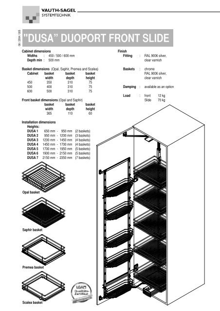
"DUSA” DUOPORT FRONT SLIDE<br />
Cabinet dimensions<br />
Widths : 450 / 500 / 600 mm<br />
Depth min : 500 mm<br />
Basket dimensions (Opal, Saphir, Premea and Scalea)<br />
Cabinet basket basket basket<br />
width depth height<br />
450 350 310 75<br />
500 400 310 75<br />
600 500 310 75<br />
Front basket dimensions (Opal and Saphir)<br />
basket basket basket<br />
width depth height<br />
365 110 60<br />
Finish<br />
Fitting : RAL 9006 silver,<br />
clear varnish<br />
Baskets : chrome<br />
RAL 9006 silver,<br />
clear varnish<br />
Damping : available as an option<br />
Load : <strong>front</strong> 12 kg<br />
Slide 70 kg<br />
Installation dimensions<br />
Heights:<br />
DUSA 1 650 mm - 950 mm (2 baskets)<br />
DUSA 2 950 mm - 1200 mm (3 baskets)<br />
DUSA 3 1200 mm - 1450 mm (4 baskets)<br />
DUSA 4 1450 mm - 1700 mm (4 baskets)<br />
DUSA 5 1700 mm - 1950 mm (5 baskets)<br />
DUSA 6 1900 mm - 2150 mm (5 baskets)<br />
DUSA 7 2150 mm - 2350 mm (7 baskets)<br />
Opal basket<br />
Saphir basket<br />
Premea basket<br />
Scalea basket
1 Fit bottom guide unit<br />
Screw the bottom guide unit, 173 mm from the<br />
<strong>front</strong> edge of the cabinet, as per the drawing, to<br />
the middle of the bottom shelf<br />
Fastening material (not included):<br />
Pan head screws 4,0 x 16<br />
or Euro screws 6,3 x 13<br />
Pan head screws 4.0 x 16<br />
or Euro screws 6.3 x 13<br />
Bottom shelf<br />
Cabinet <strong>front</strong> edge<br />
Guide unit<br />
Bottom shelf<br />
213<br />
181<br />
128<br />
173<br />
Cabinet <strong>front</strong> edge<br />
453<br />
485<br />
4 Fit sliding frame<br />
Pull the bottom guide out of the cabinet<br />
to the stop and fit the sliding frame with<br />
the holes over the adjusting screws<br />
provided. Push down the sliding frame<br />
until it engages in the guide.<br />
Now pull the top ball bearing guide also<br />
out to the stop and pull up the top sliding<br />
section of the frame until it is underneath<br />
the top guide such that the two fastening<br />
pins on the top guide protrude through<br />
the cover plate. Secure these pins with<br />
the plastic clips. Now push in the entire<br />
sliding frame and pull it back out again,<br />
then finally tighten the clamping screws<br />
on the sliding frame.<br />
2 Fit top guide<br />
Screw the top guide, 170 mm from the <strong>front</strong> edge<br />
of the cabinet, to the middle of the top<br />
Fastening material (not included):<br />
Pan head screws 4,0 x 16<br />
or Euro screws 6,3 x 13<br />
Top<br />
64<br />
72<br />
80<br />
16<br />
Top<br />
401<br />
393<br />
385<br />
8<br />
Ball bearing guide<br />
170<br />
225<br />
233<br />
241<br />
Cabinet <strong>front</strong> edge<br />
Cabinet <strong>front</strong> edge<br />
Pan head screws 4.0 x 16<br />
or Euro screws 6.3 x 13<br />
3 Fit coupling arms top / bottom<br />
When fitting the coupling arms it is to<br />
be ensured that the straight coupling<br />
arm is fitted at the top, and the bent<br />
coupling arm is fitted at the bottom.<br />
The brackets for the coupling arms<br />
are (with 110° hinges) to be fastened<br />
such that from the edge of the<br />
cabinet (hinge-side) to the 1st screw<br />
hole on the bracket there is a<br />
distance of "94 mm + door overlap".<br />
Fastening material (not included):<br />
Pan head screws 4,0 x 16<br />
or Euro screws 6,3 x 13<br />
20 mm +<br />
door overlap<br />
20 mm +<br />
door overlap<br />
32<br />
94 mm +<br />
door overlap<br />
Door<br />
Pan head screws 4.0 x 16<br />
or Euro screws 6.3 x 13<br />
Coupling arm<br />
Top of door<br />
Bracket<br />
Bottom of door<br />
Bracket<br />
Coupling arm<br />
Pan head screws 4.0 x 16<br />
or Euro screws 6.3 x 13
Guide unit<br />
Sliding frame<br />
Top<br />
Threaded<br />
sleeve<br />
Top coupling arm<br />
Flange sleeve<br />
M6 x 12<br />
Plastic<br />
clip<br />
Clamping<br />
screw<br />
Ball bearing guide<br />
Cover plate<br />
Sliding section<br />
5 Align sliding frame<br />
With the aid of the two adjusting<br />
screws (bottom) the frame can be<br />
aligned vertically: <strong>front</strong> adjusting<br />
screw anticlockwise - frame is<br />
raised at the <strong>front</strong> and tilts to the<br />
rear, rear screw anticlockwise -<br />
frame is raised at the rear and<br />
tilts to the <strong>front</strong>, by turning the<br />
screws clockwise the frame<br />
behaves in the opposite manner.<br />
With the aid of these adjusting<br />
screws the frame can also be<br />
raised or lowered if necessary by<br />
adjusting both screws by the<br />
same amount.<br />
Bottom coupling arm<br />
Flange sleeve<br />
Pin<br />
Table A<br />
Locking clip<br />
Washer<br />
Bearing pin<br />
Plastic bracket<br />
Pan head screws<br />
4.0 x 16<br />
B<br />
Adjusting screws<br />
Installation Dimension Dimension<br />
heights "A" "B"<br />
DUSA 1 650 - 950 190<br />
DUSA 2 950 - 1200 510<br />
DUSA 3 1200 - 1450 718<br />
DUSA 4 1450 - 1700 162 718<br />
DUSA 5 1700 - 1950 1118<br />
DUSA 6 1900 - 2150 1118<br />
DUSA 7 2150 - 2350 1118<br />
Rail<br />
5 mm spacer<br />
available as an<br />
optional extra<br />
64<br />
A 64<br />
If may be necessary, depending on the<br />
design of the hinges, to fit spacers to<br />
increase the distance between the rail<br />
and side of the cabinet. These are<br />
available as an optional extra.<br />
15 32<br />
31<br />
6 Connect frame to <strong>front</strong><br />
Pull out the frame, screw the top<br />
coupling arm together with the<br />
flange sleeve and the M 6 x 12<br />
screw to the threaded sleeve on<br />
the top cover plate. Fit the bottom<br />
coupling arm together with the<br />
flange sleeve and a spacer to the<br />
pin and secure with the washer<br />
and locking clip.<br />
Fastening material:<br />
Screw M6 x 12<br />
Flange sleeve 2 off<br />
Washer<br />
Locking clip<br />
7 Fit plastic brackets<br />
The bottom plastic bracket is to<br />
be fitted such that the distance<br />
between the bottom shelf and the<br />
bottom fastening holes is the<br />
same as dimension "A" as per<br />
table A. The position of the top<br />
plastic bracket is dependent on<br />
the installation height. The<br />
distance "B" is to be found in<br />
table A.<br />
If there are fouls with existing<br />
<strong>front</strong> hinges, then the dimension<br />
"A" will need to be adjusted as<br />
appropriate - Caution: this<br />
situation must also be taken into<br />
account in point 8 "Fit <strong>front</strong><br />
frame"!<br />
Now place the rails in the plastic<br />
brackets and connect with<br />
bearing pins<br />
Fastening material for fitting<br />
without spacer<br />
(not included):<br />
Pan head screws 4.0 x 16<br />
or Euro screws 6.3 x 13
Table B<br />
Installation Dimension Dimension<br />
heights "C" "D"<br />
DUSA 1 650 - 950 499<br />
DUSA 2 950 - 1200 819<br />
DUSA 3 1200 - 1450 1059<br />
DUSA 4 1450 - 1700 47 1219<br />
DUSA 5 1700 - 1950 1619<br />
DUSA 6 1900 - 2150 1619<br />
DUSA 7 2150 - 2350 1619<br />
Front frame<br />
Rail<br />
+ door overlap<br />
Pan head screws<br />
4.0 x 20 mm<br />
Bracket<br />
+ door overlap<br />
door overlap<br />
D<br />
C 32 32<br />
Screw<br />
4.0 x 8 mm<br />
Bracket<br />
13<br />
door overlap<br />
8 Fit <strong>front</strong> frame<br />
Mark or pre-drill the holes for<br />
the bottom bracket for the <strong>front</strong><br />
frame such that the distance<br />
between the bottom edge of<br />
the <strong>front</strong> and the bottom hole is<br />
the same as dimension "C" as<br />
per table B. The position of the<br />
top plastic bracket is<br />
dependent on the installation<br />
height. The distance "D" is to<br />
be found in table B. Caution: if<br />
the dimension "A" was correc<br />
ted under point 7, then the<br />
dimensions "C" and "D" must<br />
be offset by the same amount!<br />
Now push the plastic brackets<br />
into the <strong>front</strong> frame as per the<br />
drawing and secure in the<br />
frame with a screw - during this<br />
process take into account the<br />
corresponding cabinet width.<br />
Push the <strong>front</strong> frame guides<br />
onto the rollers on the rails.<br />
Screw the plastic brackets to<br />
the <strong>front</strong>.<br />
Fastening material:<br />
Pan head screws 4.0 x 20<br />
(not included)<br />
Fastening screws 4.0 x 8<br />
Front frame<br />
Locking clip<br />
Plastic clip<br />
9 Fit the baskets<br />
The plastic clip (the clips are<br />
symmetrical) is clipped into the<br />
holes on the sliding frame. The<br />
baskets are now hung on the<br />
sliding frame with the top wire<br />
on the side rail in the plastic<br />
clip. The height of the baskets<br />
can be adjusted by moving the<br />
clips. The wire hooks on the<br />
(trapezoid-shaped) baskets on<br />
the <strong>front</strong> frame are hung in the<br />
slots on the <strong>front</strong> frame. Then<br />
fit the basket locking clips<br />
above the hooks and secure.<br />
Baskets table<br />
Cabinet width Basket width<br />
450 mm 350 mm<br />
500 mm 400 mm<br />
600 mm 500 mm<br />
Please note:<br />
The cabinet must be securely fastened to the wall to prevent it from tilting.<br />
Appropriate fixing material is not supplied with the cabinet.<br />
We reserve the right to make technical changes and to improve product specifications.<br />
Vauth-Sagel SYSTEMTECHNIK<br />
GmbH & Co.KG<br />
Neue Straße 27<br />
D-33034 Brakel-Erkeln<br />
Tel. +49-52 72/6 01-01<br />
Fax. +49-52 72/6 01-193<br />
www.vauth-sagel.de<br />
e-mail: VS@Vauth-Sagel.de