Vertical Bench Milling Machine - Harbor Freight Tools
Vertical Bench Milling Machine - Harbor Freight Tools
Vertical Bench Milling Machine - Harbor Freight Tools

You also want an ePaper? Increase the reach of your titles
YUMPU automatically turns print PDFs into web optimized ePapers that Google loves.
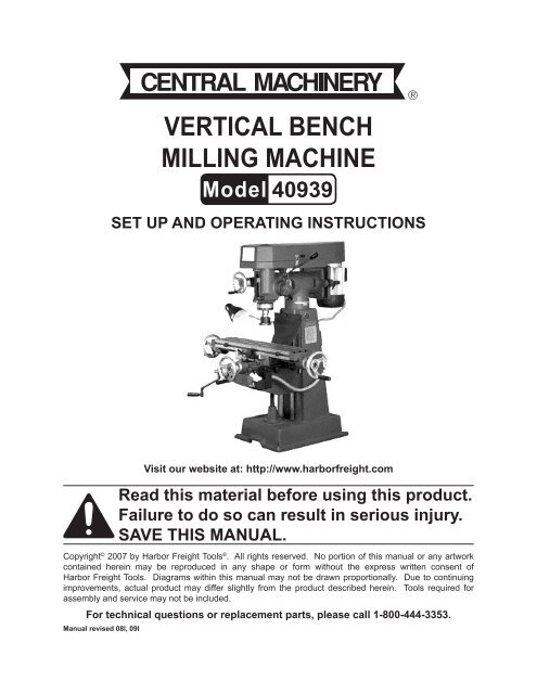
<strong>Vertical</strong> <strong>Bench</strong><br />
<strong>Milling</strong> <strong>Machine</strong><br />
40939<br />
Set up and Operating Instructions<br />
Visit our website at: http://www.harborfreight.com<br />
Read this material before using this product.<br />
Failure to do so can result in serious injury.<br />
Save this manual.<br />
Copyright © 2007 by <strong>Harbor</strong> <strong>Freight</strong> <strong>Tools</strong> ® . All rights reserved. No portion of this manual or any artwork<br />
contained herein may be reproduced in any shape or form without the express written consent of<br />
<strong>Harbor</strong> <strong>Freight</strong> <strong>Tools</strong>. Diagrams within this manual may not be drawn proportionally. Due to continuing<br />
improvements, actual product may differ slightly from the product described herein. <strong>Tools</strong> required for<br />
assembly and service may not be included.<br />
For technical questions or replacement parts, please call 1-800-444-3353.<br />
Manual revised 08l, 09l
SPECIFICATIONS<br />
Electrical<br />
220 V~ / 60Hz / 10 A<br />
Requirements<br />
Table Size 6-1/2” x 26”<br />
Long. Travel 15-1/2” Max.<br />
Cross Travel 6” Max.<br />
<strong>Vertical</strong> Travel 7.68” Max.<br />
T-Slot 1/2” (3)<br />
Spindle Travel 2-3/4”<br />
Lead Screw 1” x 8tpi<br />
Spindle Taper R8<br />
Swing 13”<br />
Head Tilt<br />
45 o L and R<br />
Motor<br />
2 HP, 1720 RPM<br />
Speeds<br />
9 Speeds:<br />
240, 355, 545, 735, 1342,<br />
1425, 1650, 2350, 2885 RPM<br />
Base Dimensions 22” x 16”<br />
Features<br />
• This model is a compact vertical milling machine. It is easy to set up. The controls<br />
are designed for operator convenience, including dual table hand wheels.<br />
• This machine is practical for technical schools, small parts production, toolrooms,<br />
R&D work, maintenance shops, and hobby use.<br />
• This machine is ideally suited for many operations, including conventional milling,<br />
compound angle milling, engraving, and jig boring.<br />
• All the Ways are hand finished for perfect bearing alignment. The table is ground<br />
for accurate squareness. Castings are high strength material. They are aged for<br />
several months, before normalizing and tempering, to minimize deformation.<br />
Save this manual<br />
You will need the manual for the safety warnings and cautions, assembly instructions,<br />
operating procedures, maintenance procedures, trouble shooting, parts list, and<br />
diagram. Keep your invoice with this manual. Write the invoice number on the inside of<br />
the front cover. Keep both this manual and your invoice in a safe, dry place for future<br />
reference.<br />
SAFETY WARNING & CAUTIONS<br />
WARNING!<br />
The Warnings, Cautions, and Instructions discussed in this instruction manual<br />
cannot cover all possible conditions and situations that may occur. It must be understood<br />
by the operator that common sense and caution are factors which cannot<br />
be built into this product, but must be supplied by the operator.<br />
READ ALL INSTRUCTIONS BEFORE USING THIS TOOL!<br />
1.<br />
KEEP WORK AREA CLEAN. Cluttered areas invite injuries.<br />
REV 09l<br />
SKU 40939 For technical questions, please call 1-800-444-3353. Page 2
2.<br />
3.<br />
4.<br />
5.<br />
6.<br />
OBSERVE WORK AREA CONDITIONS. Do not use tools in damp, wet, or poorly<br />
lit locations. Don’t expose to rain. Keep work area well lit. Do not use electrically<br />
powered equipment in the presence of flammable gases or liquids.<br />
KEEP CHILDREN AWAY. Children must never be allowed in the work area. Do not<br />
let them handle machines, tools, or equipment.<br />
STORE IDLE EQUIPMENT. When not in use, tools must be locked up in a dry<br />
location to inhibit rust. Always lock up tools and keep out of reach of children.<br />
DO NOT FORCE THE TOOL. It will do the job better and more safely at the rate<br />
for which it was intended. Do not use inappropriate attachments in an attempt to<br />
exceed the tool’s capacities.<br />
USE THE RIGHT TOOL FOR THE JOB. Do not use a tool for a purpose for which<br />
it was not intended.<br />
7. Dress Properly Do not wear loose clothing or jewelry, as they can be caught<br />
in moving parts. Non-skid footwear is recommended. Wear restrictive hair covering<br />
to contain long hair. Always wear appropriate work clothing.<br />
8. USE EYE, EAR and breathing PROTECTION. Always wear ANSI approved<br />
impact safety goggles if you are producing metal filings or wood chips. Wear an<br />
ANSI approved dust mask or respirator when working around metal, wood, and<br />
chemical dusts and mists. Use ANSI approved ear protection when working in a<br />
loud or noisy environment.<br />
9.<br />
10.<br />
11.<br />
12.<br />
13.<br />
14.<br />
DO NOT ABUSE THE POWER CORD. Protect the power cord from damage,<br />
either from impacts, pulling or corrosive materials. Do not yank machine’s cord to<br />
disconnect it from the receptacle.<br />
DO NOT OVERREACH. Keep proper footing and balance at all times. Do not<br />
reach over or across running machines.<br />
MAINTAIN TOOLS WITH CARE. Keep tools sharp and clean for better and safer<br />
performance. Follow instructions for lubricating and changing accessories. Inspect<br />
power cord periodically and, if damaged, have it repaired by an authorized technician.<br />
Inspect all hydraulic seals for leaks prior to use. Control handle and power<br />
switch must be kept clean, dry, and free from oil and grease at all times.<br />
REMOVE ADJUSTING KEYS AND WRENCHES. Be sure that keys and adjusting<br />
wrenches are removed from the tool or machine work surface before operation.<br />
AVOID UNINTENTIONAL STARTING. Be sure that you are prepared to begin work<br />
before turning the start switch on.<br />
STAY ALERT. Watch what you are doing. Do not operate this machine when you<br />
are tired.<br />
SKU 40939 For technical questions, please call 1-800-444-3353. Page 3
15. Do Not operate this machine while under the influence of alcohol,<br />
drugs, or prescription medicines.<br />
16.<br />
17.<br />
CHECK FOR DAMAGED PARTS. Before using any tool, any part that appears<br />
damaged should be carefully checked to determine that it will operate properly and<br />
perform its intended function. Check for alignment and binding of moving parts,<br />
any broken parts or mounting fixtures, and any other condition that may affect<br />
proper operation. Any part that is damaged should be properly repaired or replaced<br />
by a qualified technician. Do not use the tool if any switch does not turn on and off<br />
properly.<br />
REPLACEMENT PARTS AND ACCESSORIES. When servicing, use only identical<br />
replacement parts intended for use with this tool. Replacement parts are available<br />
from <strong>Harbor</strong> <strong>Freight</strong> <strong>Tools</strong>. Use of any other parts will void the warranty.<br />
Special Warnings when using this <strong>Vertical</strong> Mill<br />
Using this <strong>Vertical</strong> Mill may create special hazards.<br />
Take particular care to safeguard yourself and those around you.<br />
1. Electrical Safety. Never operate any tool if there is an electrical hazard. Never<br />
operate an electrical tool in wet conditions. Never operate a tool with an improper<br />
electrical cord or extension cord. Never operate an electrical tool unless you are<br />
plugged into a properly grounded outlet, which supplies 220 Volts at 60 Hz. We<br />
recommend you use a circuit which is protected by an appropriate circuit breaker.<br />
2. Ejected Material. Use safe practices to avoid injury from ejected material. Because<br />
the <strong>Milling</strong> tools and workpieces turn at high speed, there is a danger of<br />
being injured by materials that may be ejected. Always wear ANSI-certified eye<br />
protection. Never attempt to machine any item if it is not adequately held. Always<br />
stand to one side of the plane in which the materials are spinning, to avoid being<br />
hit if an item is ejected. Never allow bystanders to be in the proximity of the <strong>Vertical</strong><br />
Mill while in operation.<br />
3. Entanglement. Use extreme caution to prevent loose materials from being caught<br />
in the machine. Never operate this mill with loose clothing, long hair, jewelry, or<br />
other items which may become caught in the tools or workpieces. In case of entanglement,<br />
press the OFF switch immediately.<br />
NOTICE: No list of warnings can be all inclusive. The operator must supply common<br />
sense, and operate this tool in a safe manner.<br />
SKU 40939 For technical questions, please call 1-800-444-3353. Page 4
Unpacking<br />
When unpacking, check to make sure that the item is intact and undamaged. If<br />
any parts are missing or broken, please call <strong>Harbor</strong> <strong>Freight</strong> <strong>Tools</strong> at the number shown<br />
on the cover of this manual as soon as possible.<br />
Installation<br />
1.<br />
2.<br />
3.<br />
It is important that the machine be located on a hard, solid, level floor. Find a<br />
location that supplies easy access to 220 Volt electrical service. Make sure this<br />
machine is located in a well-lighted and well ventilated area. The floor should be<br />
resistant to vibration.<br />
To set the machine on a solid concrete foundation, it’s advisable to apply a little<br />
grout to touch up any unevenness in this concrete in order to get a solid foundation<br />
at all points.<br />
When setting machine on a floor that has any surface irregularities, shims should<br />
be used to correct this condition to the greatest extent possible.<br />
PRE-LUBRICATION<br />
1.<br />
2.<br />
Thoroughly clean the machine with an appropriate solvent. Do not use gasoline,<br />
kerosene or other flammable liquids.<br />
Lubricate all the slide ways with S.A.E. #10 and gears with S.A.E. #30 lubricant. Be<br />
sure the machine is lubricated properly before starting.<br />
LEVELING This MACHINE<br />
Before operation, it is critical to level the work table both lengthwise and crosswise,<br />
using a precision level. It will not be possible to maintain accuracy of machined<br />
parts if the mill is not properly leveled to start.<br />
SKU 40939 For technical questions, please call 1-800-444-3353. Page 5
Electrical Wiring<br />
NOTE: This machine is designed to operate on 220 Volt / 60 Hz / Single Phase power<br />
supply only. This machine is not supplied with a plug. This is because the correct<br />
plug will vary depending on the local service.<br />
1.<br />
The power supply cable enters the Base Column (#74) on the right side. Electrical<br />
connections are made within the Terminal Box (#141). This can be accessed by<br />
removing the Back Plate (#134).<br />
WARNING: Do not attempt to wire this machine yourself. Contact a qualified electrician<br />
to install the correct plug, and test your power supply to assure that this machine<br />
can be operated safely.<br />
2.<br />
The Switch Box (#115) is located on the left side of the column. This box provides<br />
an On/Off switch for machine operation. An Accessory Light (#117) is provided on<br />
the left side of the machine.<br />
NOTICE: 220 Volt systems deliver highly energetic electricity which is capable of causing<br />
lethal injury. Do not operate this machine without first obtaining professional<br />
installation and safety inspection to prevent operator injury.<br />
Wiring Diagram<br />
Wiring Diagram Key<br />
K1: Electric Power Switch<br />
K2: Spindle Rotation Switch<br />
K3: Light Switch<br />
SA, SB: Safety Switches<br />
UL: Switch Coil<br />
L1, L2: Motor<br />
C: Capacitor<br />
TC: Transformer<br />
FU: Fuse<br />
LB: Light Bulb<br />
SKU 40939 For technical questions, please call 1-800-444-3353. Page 6
<strong>Vertical</strong> <strong>Milling</strong> <strong>Machine</strong> Adjustments OF TABLE<br />
FEED TRAVEL<br />
Adjustments OF TABLE FEED TRAVEL<br />
Table longitudinal and cross feed can be set for any travel distance by adjusting<br />
the stop set screws that are located in front of table and at the right side of knee.<br />
ADJUSTMENT OF TABLE GIB:<br />
The table is provided with a full length tapered gib in the saddle with an adjusting<br />
screw on each end. To adjust the gib tighten the two screws until a slight drag is felt<br />
when moving the table by hand. If the table is not tight enough, loosen the adjusting<br />
screw on the small end, and tighten up adjusting screw on the big end. If the feel is too<br />
tight, reverse the adjusting procedures.<br />
ADJUSTMENT OF SADDLE AND KNEE GIBS:<br />
To adjust the saddle and knee gibs, use the same method as described above is<br />
used.<br />
CLAMPING TABLE, SADDLE AND KNEE:<br />
When milling with longitudinal table feed only, it is advisable to clamp the knee with<br />
the column and the saddle with the knee to add rigidity to these members and provide<br />
for heavier cuts with a minimum of vibration. The saddle locking lever is located on the<br />
left side of the saddle. Apply moderate clamping pressure, as this will hold the saddle<br />
sufficiently rigid. The table clamping levers are located in front of saddle and should always<br />
be clamped when longitudinal movement is not required. The knee clamping lever<br />
is at the left side of knee. Leave this clamped at all times unless the knee is in operation.<br />
REMOVING THE TABLE:<br />
Remove the table as follows: hand wheel, dial holder, then bearing bracket. Turn<br />
the lead screw all the way, so that it can be removed. After completing all these steps,<br />
the table can be disassembled easily.<br />
REMOVING SADDLE:<br />
Remove as follows: hand wheel, dial holder, then bearing bracket. Turn the leadscrew<br />
all the way, loosen set screw on the middle of the saddle, take off the lead screw<br />
nut, and draw the saddle gib out. The saddle can then be removed.<br />
SKU 40939 For technical questions, please call 1-800-444-3353. Page 7
MOUNTING MOTOR AND SHIFTING BELTS FOR VARIABLE SPEEDS:<br />
The motor is mounted on a plate hinged to the pulley housing. Release the belt<br />
set unit by turning the handle at the side of the motor. Then shift the belts to the proper<br />
speed as desired. Then tighten the belt set unit. A speed change chart is attached inside<br />
the pulley cover.<br />
QUILL LOCK AND VERTICAL FEED:<br />
The handle at the right lower corner of the head is the quill lock. When vertical<br />
feed is not in use, set the handle to lock the quill and make the head more stable. The<br />
micrometer depth stop is graduated in inches. By utilizing these simple graduations, it is<br />
possible to work very accurately to different depths. A lock nut under the micrometer nut<br />
assures that the micrometer nut is secured properly.<br />
QUILL CLUTCH OF VERTICAL MILLING HEAD:<br />
The vertical feed is controlled by a hand wheel at the front of the head and a handle<br />
at the right side of the head. When the hand wheel is in use, tighten the clutch lock<br />
nut by hand, or loosen it for handle operation. Use the hand wheel for fine feeds, or the<br />
handle for fast feeds.<br />
VERTICAL HEAD AND TEE ADAPTER:<br />
The vertical milling head can be tilted 90 o on each side by loosening the four locking<br />
bolts on the TEE adapter. By loosening the two set bolts on the adapter, the vertical<br />
milling head can then be swivelled 120 O ; tighten the set bolts after swiveling. The motor<br />
and milling head must tilt together since the motor and head are suspended on the<br />
same pulley housing.<br />
SKU 40939 For technical questions, please call 1-800-444-3353. Page 8
PLEASE READ THE FOLLOWING CAREFULLY<br />
The manufacturer and/or distributor has provided the parts list and assembly<br />
diagram in this manual as a reference tool only. Neither the manufacturer or<br />
distributor makes any representation or warranty of any kind to the buyer that<br />
he or she is qualified to make any repairs to the product, or that he or she is<br />
qualified to replace any parts of the product. In fact, the manufacturer and/or<br />
distributor expressly states that all repairs and parts replacements should be<br />
undertaken by certified and licensed technicians, and not by the buyer. The buyer<br />
assumes all risk and liability arising out of his or her repairs to the original<br />
product or replacement parts thereto, or arising out of his or her installation<br />
of replacement parts thereto.<br />
PARTS LIST<br />
Part Ref. # Description<br />
1 IYT-1001 <strong>Vertical</strong> milling head<br />
2 IYT-1095 Belt housing cover<br />
3 IYT-1005 Quill<br />
4 IYT-1010 S-45-Snap ring<br />
5 IYZ-1007 Spring washer<br />
6 IYT-1002 <strong>Vertical</strong> spindle<br />
7 IYT- Cover<br />
8 IYT-1008 Bearing adjusting nut<br />
9 IYT-1009 Spindle sleeve<br />
10 IYT-1016 Pulley locking nut<br />
11 IYT-1018 Spindle pulley<br />
12 IYT-1019 Quill pinion shaft<br />
13 IYT-1047 M5x10 Screw<br />
14 IYT-l036 Clutch worm gear<br />
15 IYT-1039 Clutch<br />
16 IYT-1040 Clutch adjusting nut<br />
17 IYT-1046 Clutch cover<br />
18 IYT-1021 Pinion shaft seat<br />
19 IYT-1032 Ball handles<br />
20 IYT-1028 Hand bar holder seat<br />
21 IYT-1030 Handle bar<br />
22 IYT-1051 Worm shaft<br />
23 IYT-1053 Worm shaft sleeve<br />
24 IYT-1055 Nut for bearing<br />
25 IYT-1056 Dial<br />
26 IYT-1060 Dial positioning screw<br />
27 IYT-1057 Hand wheel<br />
28 IYT-1061 Handle<br />
29 IYT-1048 Quill locking block<br />
30 IYT-1049 Quill locking bolt<br />
31 IYT-1042 Quill stop micro screw<br />
32 IYT-1044 Micrometer nut<br />
33 IYT-1045 Quill micro stop nut<br />
34 IYT-1041 Quill stopper<br />
35 IYT- 8Mx20 Screw<br />
36 IYT Bolt washer<br />
37 IYT-1014 Draw bar<br />
Part Ref. # Description<br />
38 IYT- e5xl5 Rivet<br />
39 IYT- M5x10 Screw<br />
40 IYT-1089 Pulley cover supporting arm<br />
41 IYT- M5 Nut<br />
42 IYT-1016 Washer for bearing<br />
43 IYT-1003 7207-Bearing<br />
44 IYT-1003 6007ZZ-Bearing<br />
45 IYT-1006 6206Z-Bearing<br />
46 IYT-1082 Bearing cover<br />
47 IYT-1012 R-75-Snap ring<br />
48 IYT-1011 6009Z-Bearing<br />
49 IYT-1052 Thrust bearing<br />
50 IYT-1037 Spring<br />
51 IYT-1020 Spring<br />
52 IYT- E-19 Snap ring<br />
53 IYT-1038 M6x15-Bolt<br />
54 IYT-1076 Swivel arm<br />
55 IYT-1075 Swivel stud<br />
56 IYT R-35 Snap ring<br />
57 IYT-1079 Pulley pivot stud<br />
58 IYT-1080 V-belt pulley<br />
59 IYT-1084 Motor pulley<br />
60 IYT-1067 Motor mounting<br />
61 IYT-1068 Motor suspending pivot<br />
62 IYT-1070 Motor mounting<br />
63 IYT-1072 Motor Set Unit handle<br />
64 IYT-1071 Belt set unit<br />
65 IYT-1071 Belt set unit<br />
66 IYT-1064 <strong>Vertical</strong> Head Adaptor<br />
67 IYT-1067 10Mx35 Screw<br />
68 IYT- 10M Bolt washer<br />
69 IYT-1102 A35-Vee belt<br />
70 IYT- 10M Nut<br />
71 IYT-1081 6003Z-Bearing<br />
72 IYT-1101 A32-Vee belt<br />
73 IYT-1073 1HP, 4 pole-Motor<br />
74 IYT-2006 Column<br />
SKU 40939 For technical questions, please call 1-800-444-3353. Page 9
PARTS LIST (Continued)<br />
Part Ref. # Description<br />
75 IYT-1073 Table<br />
76 IYT-2062 Table gib<br />
77 IYT-2059 Adjusting screw<br />
78 IYT-2082 Longitudinal bearing bracket<br />
79 IYT-2079 Longitudinal lead screw<br />
80 IYT-2084 Nut for bearing<br />
81 IYT-2080 Longitudinal feed nut<br />
82 IYT-2081 5Mx25 Screw<br />
83 IYT-2087 Dial<br />
84 IYT-2060 Dial positioning screw<br />
85 IYT-2089 Hand wheel<br />
86 IYT-2091 Handle bar<br />
87 IYT-2103 Long travel adjusting screw<br />
88 IYT-2104 Adjusting screw sleeve<br />
89 IYT-2068 Table stopper<br />
90 IYT-2060 Table locking screw<br />
91 IYT-2060 Handle bar<br />
92 IYT-2058 Saddle<br />
93 IYT-2058 Saddle gib<br />
94 IYT-2069 Rubber sheet<br />
95 IYT-2401 Cross lead screw<br />
96 IYT-2037 Cross feed nut<br />
97 IYT-2042 Cross feed bearing bracket<br />
98 IYT-2068 Stop block<br />
99 IYT-2102 Stop block fixture<br />
100 IYT-2103 Cross travel adjusting screw<br />
101 IYT-2104 Adjusting screw sleeve<br />
102 IYT-2015 Knee<br />
103 IYT-2016 Knee gib<br />
104 IYT-2017 Knee locking screw<br />
105 IYT-2019 Gear shaft sleeve<br />
106 IYT-2026 Gear shaft<br />
108 IYT-2029 Elevating handle clutch<br />
109 IYT-2030 Handle arm<br />
Part Ref. # Description<br />
110 IYT-2012 Elevating gear<br />
111 IYT-2009 Elevating lead screw<br />
112 IYT-2007 Elevating lead screw set nut<br />
113 IYT-2059 Chip guard<br />
114 IYT-2001 Base<br />
115 IYT-2089 Switch<br />
116 IYT-2002 1/4”x2” Bolt<br />
117 IYT-2097 Light<br />
118 IYT-2069 Rubber sheet<br />
119 IYT-119 6Mx25 Bolt<br />
120 IYT-2010 6004Z-Bearing<br />
121 IYT-121 6xl5 key<br />
122 IYT-2024 Washer<br />
123 IYT-2008 6Mx15 Bolt<br />
124 IYT-124 6Mx35 Bolt<br />
125 IYT-2084 6004Z-Bearing<br />
126 IYT-126 S-18 Snap ring<br />
127 IYT-2018 0il cup<br />
128 IYT-128 5x5x20 Key<br />
129 IYT-129 M5x10 Bolt<br />
130 IYT-130 6Mx45 Bolt<br />
131 IYT-131 6Mxl5 Bolt<br />
132 IYT-132 S-18 Snap ring<br />
133 IYT-133 10M Bolt<br />
134 IYT-134 Back Plate<br />
135 IYT-135 M6x8 Bolt<br />
136 8Mx25 Bolt<br />
137 AW09 Washer<br />
138 7x7x2C Key<br />
139 IYT-139 Iron sheet soft pipe<br />
140 IYT-140 Cable<br />
141 IYT-141 Terminal<br />
142 IYT-142 Pipe head<br />
Record Product’s Serial Number Here:<br />
Note: If product has no serial number, record month and year of purchase instead.<br />
Note: Some parts are listed and shown for illustration purposes only, and are not available<br />
individually as replacement parts.<br />
SKU 40939 For technical questions, please call 1-800-444-3353. Page 10
Base assembly diagram<br />
SKU 40939 For technical questions, please call 1-800-444-3353. Page 11
Head assembly diagram<br />
SKU 40939 For technical questions, please call 1-800-444-3353. Page 12
Limited 1 year / 90 Day warranty<br />
<strong>Harbor</strong> <strong>Freight</strong> <strong>Tools</strong> Co. makes every effort to assure that its products meet high<br />
quality and durability standards, and warrants to the original purchaser that for a period<br />
of ninety days from date of purchase that the engine/motor, the belts (if so equipped),<br />
and the blades (if so equipped) are free of defects in materials and workmanship. <strong>Harbor</strong><br />
<strong>Freight</strong> <strong>Tools</strong> also warrants to the original purchaser, for a period of one year from<br />
date of purchase, that all other parts and components of the product are free from<br />
defects in materials and workmanship (90 days if used by a professional contractor or<br />
if used as rental equipment). This warranty does not apply to damage due directly or<br />
indirectly, to misuse, abuse, negligence or accidents, repairs or alterations outside our<br />
facilities, normal wear and tear, or to lack of maintenance. We shall in no event be liable<br />
for death, injuries to persons or property, or for incidental, contingent, special or consequential<br />
damages arising from the use of our product. Some states do not allow the<br />
exclusion or limitation of incidental or consequential damages, so the above limitation<br />
of exclusion may not apply to you. This warranty is expressly in lieu of all<br />
other warranties, express or implied, including the warranties of<br />
merchantability and fitness.<br />
To take advantage of this warranty, the product or part must be returned to us with<br />
transportation charges prepaid. Proof of purchase date and an explanation of the complaint<br />
must accompany the merchandise. If our inspection verifies the defect, we will either<br />
repair or replace the product at our election or we may elect to refund the purchase<br />
price if we cannot readily and quickly provide you with a replacement. We will return repaired<br />
products at our expense, but if we determine there is no defect, or that the defect<br />
resulted from causes not within the scope of our warranty, then you must bear the cost<br />
of returning the product.<br />
This warranty gives you specific legal rights and you may also have other rights<br />
which vary from state to state.<br />
3491 Mission Oaks Blvd. • PO Box 6009 • Camarillo, CA 93011 • (800) 444-3353<br />
SKU 40939 For technical questions, please call 1-800-444-3353. Page 13