
Create successful ePaper yourself
Turn your PDF publications into a flip-book with our unique Google optimized e-Paper software.
16<br />
Training Assembly 9<br />
Program:<br />
• Warm Up<br />
level 1 / 20 sec level 2 / 20 sec level 3 / 20 sec level 4 / 20 sec<br />
level 5 / 20 sec level 6 / 20 sec total 120 sec<br />
• Beginners Workout<br />
level 2 / 10 sec level 3 / 10 sec level 4 / 10 sec level 5 / 10 sec<br />
level 6 / 10 sec level 7 / 10 sec total 60 sec<br />
• Intermediate Workout<br />
level 7 / 15 sec level 8 / 15 sec level 9 / 15 sec level 10 / 15 sec<br />
level 11 / 15 sec level 12 / 15 sec total 90 sec<br />
• Advanced Workout<br />
level 10 / 20 sec level 11 / 20 sec level 12 / 20 sec level 13 / 20 sec<br />
level 14 / 20 sec level 15 / 20 sec total 120 sec<br />
• Massage<br />
level 13 / 20 sec level 15 / 20 sec level 13 / 20 sec level 15 / 20 sec<br />
level 14 / 20 sec level 15 / 20 sec total 120 sec<br />
In Manual mode:<br />
Time and Intensity are only adjustable in Manual mode. If Time and Intensity is not<br />
set, the program will not start.The program will start once the start / stop button<br />
has been pre s s e d . Time and Intensity up/down function key will no longer respond if<br />
mode is changed to Warm up/ Beg wo r kout/ Int. wo r kout/ Adv wo r kout/ Massage.<br />
In Warm up/ Beg wo rkout/ Int. wo rkout/ Adv wo rkout/ Massage Mode:<br />
The program will start once the start / stop button has been pressed. Once the<br />
program has started in either Warm up/ Beg workout/ Int. workout/ Adv workout<br />
/ Massage mode, the Time and Intensity is not adjustable. (Only use Start/Stop<br />
button for Start/Stop function).<br />
Standard operation:<br />
Select the desired program length. In order to do this, press the “Timer” switch.<br />
Every time you press the switch the time will be increased and this will be shown<br />
in the program time display.<br />
Press on the “+ “or “- “speed button to set the required vibration speed. Every<br />
time you press on the button the speed will be either increased or decreased by<br />
one level.The actual speed of vibration will be shown in the corresponding display.<br />
Important: If you do not set a program length it is not possible to select a<br />
program, meaning that you will not be able to begin training!<br />
Assembling the equipment<br />
Set-up<br />
Remove all of the parts from the packaging and lay them carefully on a level<br />
surface. Place a protective cover underneath them in order to avoid damaging any<br />
delicate surfaces.<br />
Remove the protective padding and plastic packaging. Check that you have all parts<br />
and that none have been damaged during transportation. Follow these assembly<br />
instructions step-by-step in order to avoid incorrect assembly.<br />
Please remove the transportation lock<br />
before first use.<br />
To do this please re m ove both of the safety bolts using the<br />
w rench prov i d e d . S t o re these bolts somew h e re safe and<br />
reattach them should you wish to move the machine.<br />
To replace the bolts simply screw into place and hand<br />
t i g h t e n .<br />
Important:<br />
• Ensure that the cable is not bent or trapped by the housing parts.<br />
• Only connect the equipment to the main power supply once it is completely<br />
assembled.<br />
• Protect flooring on which the equipment is to be placed by covering with a mat.<br />
• Ensure that the cable is not a trip hazard by securing it.<br />
• It is advisable to place <strong>Total</strong> <strong>Vibes</strong> in a location where children will not be able<br />
to access it.<br />
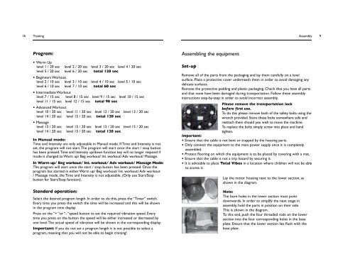
Lay the motor housing next to the lower section, as<br />
shown in the diagram.<br />
Note:<br />
The bore holes in the lower section must point<br />
downwards. In order to simplify the next stage in<br />
assembly, hold the parts in position on their side.<br />
This is shown in the diagram.<br />
To this end, push the four threaded rods on the lower<br />
section into the four corresponding holes in the base<br />
plate. Ensure that the lower section lies flush with the<br />
base plate.