Orbitrek Elite Instruction Manual - Thane
Orbitrek Elite Instruction Manual - Thane
Orbitrek Elite Instruction Manual - Thane

Create successful ePaper yourself
Turn your PDF publications into a flip-book with our unique Google optimized e-Paper software.
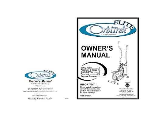
OWNER’S<br />
MANUAL<br />
Safety Notice..............2<br />
Assembly & Usage 3-7<br />
Exploded View ..........8<br />
Parts List ..............9-10<br />
Exercise Computer ..11<br />
O w n e r’s <strong>Manual</strong><br />
This Product is Brought to You by:<br />
<strong>Thane</strong> International, Inc. La Quinta, CA 92253<br />
<strong>Thane</strong> Direct Canada, Inc. Toronto, Ontario<br />
<strong>Thane</strong> Direct UK Limited Admail ADM3996 London W1T 1ZU<br />
www.thane.com<br />
www.thanefitness.com<br />
Making Fitness Fun!®<br />
(9/02)<br />
IMPORTANT!<br />
Please read all instructions<br />
carefully before using this<br />
product. Retain this manual<br />
for future reference.<br />
TYPE:BK2080<br />
<strong>Thane</strong> International, Inc.<br />
La Quinta, CA 92253<br />
<strong>Thane</strong> Direct Canada, Inc.<br />
Toronto, Ontario<br />
<strong>Thane</strong> Direct UK Limited<br />
Admail ADM3996 London W1T 1ZU<br />
www.thane.com
Owner’s <strong>Manual</strong><br />
IMPORTANT SAFETY NOTICE<br />
Note the following precaution before assembling or operating the machine.<br />
1. THE MAXIMUM WEIGHT CAPACITY OF THE ORBITREK ELITE IS 275 LBS (125 kgs).<br />
Persons whose body weight exceeds this limit should NOT use this machine.<br />
2. Keep children and pets away from the <strong>Orbitrek</strong> <strong>Elite</strong> at all times. DO NOT leave<br />
unattended children in the same room with the machine.<br />
3. Handicapped or disabled persons should not use the <strong>Orbitrek</strong> <strong>Elite</strong> without the presence<br />
of a qualified health professional of a qualified health professional or physician.<br />
4. If the user experiences dizziness, nausea, chest pain, or any other abnormal symptoms,<br />
STOP the workout at once. CONSULT A PHYSICIAN IMMEDIATELY.<br />
5. Before beginning training, remove all within a radius of 2 meters from the machine.<br />
DO NOT place any sharp objects around the <strong>Orbitrek</strong> <strong>Elite</strong>.<br />
6. Position the <strong>Orbitrek</strong> <strong>Elite</strong> on a clear, level surface away from water and moisture.<br />
Place mat under the unit to help keep the machine stable and to protect flooring.<br />
7. Use the <strong>Orbitrek</strong> <strong>Elite</strong> only for its intended use as described in this manual.<br />
DO NOT use any other accessories not recommended by the manufacturer.<br />
8. Assemble the machine exactly as the descriptions in the instruction manual.<br />
9. Check all bolts and other connections before using the machine for the first time and<br />
ensure that the trainer is in the safe condition.<br />
10. Hold a routine inspection of the equipment.Pay special attention to components which<br />
are the most susceptible to wear off, i.e.connecting points and wheels. The defective<br />
components should be replaced immediately. The safety level of this equipment can only<br />
be maintained by doing so. Please don't use the <strong>Orbitrek</strong> <strong>Elite</strong> until it is repaired well.<br />
11. NEVER operate the <strong>Orbitrek</strong> <strong>Elite</strong> if it is not functioning properly.<br />
12. This machine can be used for only one person’s training at a time.<br />
13. Do not use abrasive cleaning articles to clean the machine. Remove drops of sweat<br />
from the machine immediately after finishing training.<br />
14. Always wear appropriate workout clothing when exercising. Running or aerobic shoes<br />
are also required.<br />
15. Before exercising, always do stretching first.<br />
16. The power of the machine increases with increasing the speed, and the reverse.<br />
The machine is equipped with adjustable knob, which can adjust the resistance.<br />
WARNING: BEFORE BEGINNING THIS OR ANY EXERCISE PROGRAM, CONSULT YOUR PHYSICIAN<br />
F I R S T. THIS IS ESPECIALLY IMPORTANT FOR INDIVIDUALS OVER THE AGE OF 35 OR PERSONS WITH<br />
PRE-EXISTING HEALTH PROBLEMS. READ ALL INSTRUCTIONS BEFORE USING THE ORBITREK ELITE.<br />
THANE ASSUMES NO RESPONSIBILITY FOR PERSONAL INJURY OR PROPERTY DAMAGE SUSTA I N E D<br />
BY OR THROUGH THE USE OF THIS PRODUCT.<br />
SAVE THESE INSTRUCTIONS<br />
2<br />
Owner’s <strong>Manual</strong><br />
BEFORE you begin:<br />
1. Locate a comfortable work site. Assemble your OrbiTrek <strong>Elite</strong> in an open space with adequate<br />
ventilation and lighting. Because the OrbiTrek <strong>Elite</strong> is portable, to some extent, you need not<br />
assemble it exactly where it is to be used. For your convenience, however, you should avoid<br />
hauling the machine across excessive distances, through narrow passage ways or over staircases<br />
once its assembly is complete.<br />
2. It’s a good idea to flatten out the shipping carton, and use it as a work surface when you<br />
assemble the OrbiTrek <strong>Elite</strong>. Keep a few paper towels handy since some of the components<br />
are lightly pre-greased.<br />
Notice:<br />
Find your tools. You will need the following tools to assemble the <strong>Orbitrek</strong> <strong>Elite</strong>.<br />
Ruler with both metric and English measurements<br />
Allen wrench (6# and 8#)<br />
Spanner<br />
Before assembling please check whether all needed parts are available (at the above of this instruction<br />
sheet you will you will find an exploded drawing with all single parts (marked with numbers) which this<br />
item consist of.<br />
Identify your hardware:<br />
Organize your bolts and nuts before assembly. Nuts are identified by the diameter of the cavities.<br />
For more information, refer to exploded view diagram and parts list on pages 8-10 of this manual.<br />
NO.1 LEFT HINGE BOLT<br />
ASSEMBLY INSTRUCTIONS<br />
NO.6 SPRING<br />
WASHER (1/2”)<br />
NO.7 LEFT LOCK NUT (1/2”)<br />
3<br />
NO.9 CARRIAGE BOLT (M8*60)<br />
NO.11 ARC WASHER NO.12 DOMED NUT (M8) NO.13 NUT (M8) NO.14 FLAT WASHER<br />
NO.20 BOLT (M8*45)<br />
NO.34 LOCKING<br />
KNOB<br />
NO.42 RIGHT HINGE BOLT<br />
NO.31 HINGE<br />
SCREW<br />
(3/8”*20)<br />
NO.32 SPRING<br />
WASHER (*10)<br />
NO. 33 D SHAPER<br />
WASHER<br />
NO.95<br />
PLASTIC<br />
KNOB NUT NO.38 SPINDLE BAR NO.89 RIGHT LOCK NUT (1/2”)<br />
ALLEN WRENCH 8# ALLEN WRENCH 6# SPANNER<br />
NO.93 ARC WASHER<br />
(dl=16 D=26 s=0.3)
Owner’s <strong>Manual</strong><br />
Owner’s <strong>Manual</strong><br />
Step 1: Attaching front and rear stabilizers<br />
Step 2: Attaching the Spindle Bar<br />
Attach the Front Stabilizer (No.<br />
23) and the Rear Stabilizer (No.<br />
10) to the main frame using:<br />
23<br />
Fig. 1<br />
Insert the Spindle Bar (No. 38) through the Right Connecting Tube (No. 55) into the main frame,<br />
into Left Connecting Tube (No. 24). Put a D Shaper Washer (No. 33) and a Spring Washer (No. 32)<br />
on either side of the Spindle Bar and tighten both ends using the Hinge Screws (No. 31).<br />
4 – Carriage Bolt (No. 9)<br />
4 – Arc Washers (No. 11)<br />
4 – Domed Nuts (No. 12)<br />
Place the Front Stabilizer (No.<br />
23) against the main frame and<br />
be sure the holes line up. Take<br />
two of the Carriage Bolts (No. 9)<br />
and pass them through the tube<br />
supports located on the unit.<br />
Slip the two Arc Washers (No. 11)<br />
over the threaded portions of the<br />
carriage bolts. Place the two<br />
Domed Nuts (No. 12) over the<br />
Arc Washers (No. 11) and firmly<br />
tighten down the Domed Nuts<br />
(No. 12) using the wrench provided.<br />
Notice: The Front Stabilizer (No. 23) has wheels for moving your <strong>Orbitrek</strong> <strong>Elite</strong>.<br />
Follow the same procedure for attaching rear stabilizer.<br />
9<br />
11<br />
12<br />
36<br />
12<br />
11<br />
11<br />
12<br />
9<br />
10<br />
2 – “D” Shaped Washers<br />
(No. 33)<br />
2 – Spring Washers (No. 32)<br />
2 – Hinge Screws (No. 31)<br />
I n s e rt the Right Hinge Bolt<br />
(No. 42) with Arc Wa s h e r<br />
(No. 93) through the<br />
Connecting Tube (No. 5) and<br />
s c rew it through the Crank<br />
(No. 91) until completely<br />
tight. Put Spring Washer<br />
(No. 6) on and secure the<br />
Right Hinge Bolt (No. 42)<br />
with the Right Lock Nut<br />
(No. 89) until tight. The<br />
Spring Washer (No. 6) has<br />
to be completely flattened.<br />
1 – Right Hinge Bolt (No. 42)<br />
1 – Left Hinge Bolt (No. 1)<br />
2 – Arc Washer (No. 93)<br />
2 – Spring Washer (No. 6)<br />
1 – Right Lock Nut (No. 89)<br />
1 – Left Lock Nut (No. 7)<br />
2 – Connecting Tube (No. 5)<br />
Fig. 2<br />
Repeat this procedure for the left side.<br />
#1: LEFT #42: RIGHT<br />
89 6 91 5 93<br />
CORRECT<br />
42<br />
ATTENTION:<br />
Gap<br />
LOOSE BOLT<br />
The Right and Left Hinge Bolt (No. 42 & No. 1) must fully penetrate the<br />
nylon ring inside the Connecting Tube (No. 5) and the Right and Left<br />
Crank (No. 91 & No. 83). This will ensure the stability and durability of<br />
your <strong>Orbitrek</strong> <strong>Elite</strong>.<br />
ANGLED BOLT<br />
In order to install each Hinge Bolt properly, keep it straight as the Hinge Bolt goes through the<br />
Connecting Tube and the Crank. If the Hinge Bolt is connected to the Crank at an angle, damage to<br />
both the Hinge Bolt and the Crank may occur.<br />
CAUTION: MAKE SURE ALL THE BOLTS AND NUTS ARE TIGHT PRIOR TO WORKOUT.<br />
4<br />
5
Owner’s <strong>Manual</strong><br />
Step 3: Tightening the Lock Nuts and Attaching the Pedals<br />
Owner’s <strong>Manual</strong><br />
Step 5: Connecting the sensor<br />
Tighten the both sides of Lock Nuts<br />
(No. 3) before assemblying the pedals.<br />
Attach the Right Pedal (No. 26) and Left<br />
Pedal (No. 27) to their respective Pedal<br />
Tube (No. 19) using:<br />
4 – Hex Head Bolt (No. 20)<br />
4 – Lock Nut (No. 13)<br />
4 – Flat Washer (No. 14)<br />
20<br />
27<br />
19<br />
36<br />
26<br />
20<br />
19<br />
14<br />
13<br />
Fig. 3<br />
Connect the sensor B1 & B2 as shown in Fig. 5, then install the<br />
computer (No. 37) into the support tube of the main frame<br />
(No. 36).<br />
Assembly is complete.<br />
BATTERY<br />
Fig. 5<br />
Line up the holes in the pedal with the<br />
holes on the pedal tube. Insert the Hex<br />
Head Bolt (No. 20) through the holes.<br />
Slide the Flat Washer (No. 14) and the<br />
Lock Nut (No. 13) over the Hex Head<br />
Bolt (No. 20) and tighten with the<br />
w rench.<br />
Step 4: Attaching the Handlebars<br />
14<br />
13<br />
SPANNER<br />
3<br />
To remove the computer,<br />
pull the top, slide the computer<br />
downwards and then pull from<br />
tube bracket.<br />
Battery assembly:<br />
Open the upper cover of the<br />
computer, then install the<br />
battery into the battery<br />
compartment.<br />
37<br />
36<br />
Fig. 4<br />
DUAL ACTION<br />
22<br />
40 95 ATTACH HERE<br />
FOR FIXED MODE<br />
95<br />
34<br />
34<br />
55<br />
36<br />
24<br />
You can easily switch your Right and Left Handlebars (No. 22<br />
& No. 40) between the dual-action mode and the fixed mode<br />
during the fixed mode during your workout.<br />
DUAL ACTION MODE<br />
To allow the handlebars to move along with the pedals, attach<br />
them to the coupler bars. Select a height setting that is<br />
comfortable to the user and make sure both handlebars are<br />
set at the same height. Lock each handlebar in place with lock<br />
knob (No.34) and plastic knob nut (No.95). See Fig 4.<br />
FIXED MODE<br />
To keep the handlebars stationary while you workout, attach<br />
them to the tubing on the main frame between he coupler<br />
bars. As with the dual-action mode. Set both handlebars at<br />
the same comfortable height and secure them with the lock<br />
knob (No. 34).<br />
6<br />
Tension adjustment<br />
The assembly of your <strong>Orbitrek</strong> <strong>Elite</strong> is now complete. As you try your exercises for the first time, you<br />
should adjust the tension to the correct level before you begin your full workout. Turning the adjustment<br />
knob allows you to change the tension level and vary the intensity of your workout as you exercise.<br />
To increase tension turn the tension knob to the right and top decrease tension turn the tension knob<br />
to the left.<br />
Reversible movement<br />
Insert the computer<br />
into the tube bracket.<br />
Remember, your <strong>Orbitrek</strong> <strong>Elite</strong> has REVERSIBLE movement!<br />
Forward pedaling exercises your quadriceps (front thigh muscles), while backward pedaling targets your<br />
hamstrings (back thigh muscles). Take advantage of these facts to make your workout less fatiguing and<br />
more fun.<br />
Note: <strong>Orbitrek</strong> <strong>Elite</strong> has two moveable wheels on the front stabilizer, which are easy for you to move your<br />
training bike and the end cap on the rear stabilizer can adjust the parallelism.<br />
CAUTION: MAKE SURE YOU HAVE TIGHTEN ALL THE BOLTS AND NUTS WELL BEFORE<br />
BEGINNIG YOUR WORKOUT.<br />
7
Owner’s <strong>Manual</strong><br />
EXPLODED VIEW & PARTS LIST<br />
Owner’s <strong>Manual</strong><br />
NO. NAME QUANTITY SPEC<br />
1 LEFT HINGE BOLT 1 1/2"<br />
2 BUSHING I 10 28* 16<br />
3 LOCK NUT 4 M10<br />
4 STEEL BUSHING 4 28* 14*10<br />
5 CONNECTING TUBE 2<br />
6 SPRING WASHER 2 1/2"<br />
7 LEFT LOCK NUT 1<br />
8 ADJUSTABLE END CAP 2<br />
9 CARRIAGE BOLT 4 M8*62<br />
10 REAR STABILIZER 1 50*1.5<br />
11 ARC WASHER 4<br />
12 DOMED NUT 4 M8<br />
13 LOCK NUT 4 M8<br />
14 FLAT WASHER 4 8<br />
15 HEX HEAD BOLT 4 M10*55<br />
16 SCREW 6 ST4.2*19<br />
17 LEFT HANDLEBAR COVER (L) 1<br />
18 BUSHING 2 4 18* 10*10<br />
19 PEDAL TUBE 2<br />
20 HEX HEAD BOLT 4 M8*50<br />
21 LEFT HANDLEBAR COVER (R) 1<br />
22 RIGHT HANDLEBAR 1<br />
23 FRONT STABILIZER 1<br />
24 LEFT CONNECTING TUBE 1<br />
25 FRONT END CAP 2 50*1.5<br />
26 RIGHT PEDAL 1 2<br />
27 LEFT PEDAL 1 10<br />
28 HEX HEAD BOLT 2 M6*45<br />
29 WHEEL 2 23* 6.2*32<br />
30 LOCK NUT 3 M6<br />
31 HINGE SCREW 2 3/8"*20<br />
32 SPRING WASHER 2 10<br />
33 D SHAPER WASHER 2<br />
34 LOCKING KNOB 2<br />
35 PLASTIC SLEEVE 2<br />
36 MAIN FRAME 1<br />
37 COMPUTER 1<br />
38 SPRING BAR 1<br />
39 FORM GRIP 2 33* 23*310<br />
40 LEFT HANDLEBAR 1<br />
41 HANDLEBAR END CAP 2 25.4*2<br />
42 RIGHT HINGE BOLT 1 1/2"<br />
43 RIGHT HANDLEBAR COVER (L) 1<br />
44 RIGHT HANDLEBAR COVER (R) 1<br />
45 PLASTIC SLEEVE 2<br />
46 END CAP 2 30*30*1.5<br />
47 FIXING WASHER (L) 1<br />
48 WASHER 1<br />
49 COLLAR BALL 2<br />
50 COLLAR HOUSING 2<br />
51 FIXING WASHER (R) 1<br />
52 WASHER 1 40*2.8<br />
53 CRANK SHAFT 1 17*192<br />
54 CRANK WHEEL 1 d=3.2,P=6.35<br />
55 RIGHT CONNECTIING TUBE 1<br />
56 FLAT WASHER 3 5<br />
57 LEFT CHAIN COVER 1<br />
58 FIXING NUT 2 M10*1.0<br />
8<br />
9
Owner’s <strong>Manual</strong><br />
59 NUT 2 M6<br />
60 FIXING BOLT 2 M6*55<br />
61 TENSION KNOB 1<br />
62 NUT 2 M10*1<br />
63 FLYWHEEL 1<br />
64 FLYWHEEL SHAFT 1<br />
65 LITTLE CHAIN WHEEL 1<br />
66 RIGHT CHAIN COVER 1<br />
67 NUT 1 7/8"<br />
68 SPRING 1<br />
69 DOMED NUT 1 M6<br />
70 END CAP 2<br />
71 WOOLLY BLOCK 1<br />
72 HEX HEAD BOLT 1 M5*35<br />
73 PLASTIC FRAME 1<br />
74 PLUG 1 PA<br />
75 LOCK NUT 1 M5<br />
76 SPRING COVER 1<br />
77 BREAKING CUSHION 1<br />
78 SCREW 9 ST4.2*16<br />
79 RUBBER COVER 1 32*10<br />
80 END CAP 2<br />
81 FIXING NUT 2 M10*1.25<br />
82 FIXING TUBE II 1 13.6* 10.3*25.5<br />
83 LEFT CRANK 1<br />
84 CHAIN 1<br />
85 SENSOR 1<br />
86 FIXING TUBE I 1 14*8.5<br />
87 BEARING 3 6000ZZ<br />
88 ADJUSTABLE NUT 1 15*30<br />
89 RIGHT LOCK NUT 1 1/2"<br />
90 SPRING WASHER 2 6<br />
91 RIGHT CRANK 1<br />
92 NUT 1 M14*1.5<br />
93 ARC WASHER 2 d=16 D=26 S=0.3<br />
94 FLAT WASHER 4 10<br />
95 PLASTIC KNOB NUT 2 M8<br />
BATTERY DISPOSAL:<br />
Batteries should not be considered as regular garbage. As consumer you are<br />
obliged to return finished batteries. The finished batteries can be returned to<br />
a collection base at your residential area or at places where batteries can be bought.<br />
WE RECOMMEND THE USE OF ALCALI-MANGAN BATTERIES.<br />
You will find these symbols on batteries,<br />
which contain harmful substances:<br />
Pb = Battery contains lead<br />
Cd = Battery contains cadmium<br />
Hg = Battery contains mercury Pb Cd Hg<br />
Owner’s <strong>Manual</strong><br />
SPECIFICATIONS:<br />
TIME (TMR)……………......00:00-99:59<br />
SPEED (SPD)...0.0-99.9KM/HorML/H<br />
DISTANCE (DST)……….0.00-999.9KM<br />
EXERCISE COMPUTER<br />
KEY FUNCTION:<br />
MODE: This key lets you to select and lock on to a particular function you want.<br />
OPERATION PROCEDURES:<br />
1. AUTO ON/OFF:<br />
The system turns on when any key is pressed or when it receives an input from the speed sensor.<br />
The processor turns off automatically when the speed sensor has no signal input or no key is<br />
pressed for approximately 4 minutes.<br />
2. RESET:<br />
The unit can be reset by changing the batteries or pressing the MODE key for 3 seconds.<br />
3. HOW TO PRESET TIME, DISTANCE:<br />
To choose the SCAN or LOCK if you do not want the scan mode, press the MODE key when the<br />
pointer on the function you want which begins blinking.<br />
4. FUNCTIONS:<br />
TIME: The time of exercise will be displayed by pressing MODE key until brand TMR appears.<br />
SPEED: Current speed will be shown buy pressing MODE key until brand SPD appears.<br />
DISTANCE: The distance of each workout will be displayed by pressing MODE key until brand<br />
DST appears.<br />
SCAN: Automatic display of the following functions in the order shown:<br />
TIME-SPEED-DISTANCE<br />
BATTERY:<br />
This monitor uses one battery. If improper display on monitor,<br />
Please reinstall the batteries to have a good result.<br />
10<br />
11
Owner’s <strong>Manual</strong><br />
Owner’s <strong>Manual</strong><br />
Using your <strong>Orbitrek</strong> <strong>Elite</strong> will provide you with several benefits. It will improve your physical fitness,<br />
tone your muscles and in conjunction with a calorie controlled diet, help you lose weight.<br />
1. The Warm-Up Phase<br />
This stage helps get the blood flowing around the body and the muscles working properly. It will also<br />
reduce the risk of cramp and muscle injury. It is advisable to do a few stretching exercises as shown<br />
below. Each stretch should be held for approximately 30 seconds. Do not force or jerk your muscles<br />
into a stretch. If it hurts, STOP.<br />
This is the stage where you put the effort in. After regular use, the muscles in your legs will become<br />
more flexible. Work at your own pace and be sure to maintain a steady tempo throughout. The rate of<br />
work should be sufficient to raise your heartbeat into the target zone shown on the graph below.<br />
SIDE BENDS<br />
2. The Exercise Phase<br />
FORWARD<br />
BENDS<br />
Start Position<br />
OUTER THIGH STRETCHES<br />
INNER THIGH<br />
STRETCHES<br />
CALF/ACHILLES<br />
STRETCHES<br />
Stand on the left side of the bike, grasp the handlebars (under the<br />
handlebar end caps about 100mm), then stride your left leg, place your<br />
left foot on the left pedal, then stride your right leg, place your right foot on<br />
the right pedal, adjust your hands and stand pose to a comfortable position.<br />
Moving Position<br />
Grasp the handlebars, then switch the handlebars to and<br />
fro in tandem to move along with the pedals, do elliptical<br />
cycle movement. Your <strong>Orbitrek</strong> <strong>Elite</strong> has reversable<br />
movement. Forward pedalling emphasizes your<br />
quadriceps muscle (front thighs), while backwards<br />
pedalling emphasizes your hamstrings (back thighs).<br />
Remember, if you want to change your movement<br />
direction, stop movement first.<br />
3. The Cool-Down Phase<br />
This stage should last for a minimum of 12 minutes<br />
though most people start at about 15-20 minutes.<br />
This stage lets your cardio vascular system and muscles wind down. This is a repeat of the warm up<br />
phase. First, reduce your tempo and continue at this slower pace for approximately 5 mintues before<br />
you get off your Exercise Bike. The stretching exercises should now be repeated, again remembering<br />
not to force or jerk your muscles into the stretch.<br />
As you get fitter, you may need to train longer and harder. It is advisable to train at least three times<br />
a week, and if possible to space your workouts evenly throughout the week.<br />
MUSCLE TONING<br />
To tone muscle while on your RACING BIKE you will need to have the resistance set quite high.<br />
This will put more strain on your leg muscles and may mean you cannot train for as long as you would<br />
like. If you are also trying to improve your fitness you may need to alter your training program.<br />
You should train as normal during the warm up and cool down phases, but towards the end of the<br />
exercise phase you should increase the resistance making your legs work harder. You will have to<br />
reduce your speed to keep your heart rate in the target zone.<br />
WEIGHT LOSS<br />
The important factor here is the amount of effort you put in. The harder and longer you work, the more<br />
calories you will burn. This is effectively the same as if you were training to improve your fitness, the<br />
difference being the goal.<br />
12<br />
13