CEOM8014.52 - Essential Energy
CEOM8014.52 - Essential Energy
CEOM8014.52 - Essential Energy

Create successful ePaper yourself
Turn your PDF publications into a flip-book with our unique Google optimized e-Paper software.
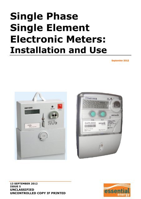
Single Phase<br />
Single Element<br />
Electronic Meters:<br />
Installation and Use<br />
September 2012<br />
13 SEPTEMBER 2012<br />
ISSUE 5<br />
UNCLASSIFIED<br />
UNCONTROLLED COPY IF PRINTED
UNCLASSIFIED<br />
OPERATIONAL MANUAL – Single Phase, Single Element Electronic Meters:<br />
Installation and Use<br />
<strong>CEOM8014.52</strong><br />
PREPARED BY:<br />
METROLOGY SPECIALIST & LABORATORY COORDINATOR<br />
AUTHORISED BY:<br />
GROUP MANAGER METERING SERVICES<br />
ASSISTANCE: METROLOGY SPECIALIST & LABORATORY COORDINATOR: 02 67017425<br />
DOCUMENT NUMBER: <strong>CEOM8014.52</strong>- ISSUE 5<br />
This plan is copyright. No part may be reproduced by any process without written permission,<br />
except as permitted under the copyright act<br />
DISCLAIMER<br />
1 <strong>Essential</strong> <strong>Energy</strong> may change the information in this document without notice. All changes<br />
take effect on the date made by <strong>Essential</strong> <strong>Energy</strong>. A print version is always an uncontrolled<br />
copy. Before using this document, please ensure that it is still current.<br />
2 This document may contain confidential information. Restrictions on the use and disclosure<br />
of confidential information by employees are set out in your contract of employment.<br />
Restrictions on the use and disclosure of confidential information by contractors are set out in<br />
your contract of engagement with <strong>Essential</strong> <strong>Energy</strong>. Sub-contractors are bound by the<br />
confidentiality provisions set out in their contract with the contractor engaged by <strong>Essential</strong><br />
<strong>Energy</strong>.<br />
2012 E S S E N T I A L E N E R G Y<br />
13 September 2012 - Issue 5<br />
Approved By: General Manager Network Support<br />
Page 2 of 12<br />
UNCLASSIFIED<br />
UNCONTROLLED COPY IF PRINTED
UNCLASSIFIED<br />
OPERATIONAL MANUAL – Single Phase Single Element Electronic Meters:<br />
Installation and Use<br />
<strong>CEOM8014.52</strong><br />
Contents Page<br />
1 INTRODUCTION ............................................................................................ 4<br />
2 WHY THESE INSTRUCTIONS ARE IMPORTANT ................................................... 4<br />
3 CHALLENGES ............................................................................................... 4<br />
4 USING THE METERS ...................................................................................... 5<br />
4.1 Common Features ............................................................................................ 5<br />
4.2 Connection ...................................................................................................... 5<br />
4.3 Configuration ................................................................................................... 5<br />
4.4 Internal Battery ............................................................................................... 5<br />
4.5 Documentation & Display Indicators .................................................................... 6<br />
4.6 Installation ...................................................................................................... 6<br />
4.6.1 Drilling template .................................................................................................. 6<br />
4.6.2 Sealing .............................................................................................................. 7<br />
4.6.3 Consumption indicator .......................................................................................... 7<br />
4.7 Errors and Warnings ......................................................................................... 8<br />
4.7.1 Error monitoring .................................................................................................. 8<br />
4.7.2 Reverse energy flow ............................................................................................ 8<br />
4.7.3 Commissioning checks ......................................................................................... 9<br />
4.8 Removal and Return ......................................................................................... 9<br />
4.8.1 Removal............................................................................................................. 9<br />
4.8.2 Return ............................................................................................................... 9<br />
5 READING THE METER .................................................................................. 10<br />
5.1 <strong>Energy</strong> – Peak ................................................................................................ 10<br />
5.2 <strong>Energy</strong> – shoulder .......................................................................................... 10<br />
5.3 <strong>Energy</strong> – Off Peak ........................................................................................... 10<br />
5.4 <strong>Energy</strong> – Total NET Export ............................................................................... 11<br />
5.5 Date ............................................................................................................. 11<br />
5.6 Time ............................................................................................................. 11<br />
5.7 Display Test ................................................................................................... 11<br />
5.8 Errors ........................................................................................................... 11<br />
6 REFERENCES .............................................................................................. 12<br />
7 REVISIONS ................................................................................................ 12<br />
13 September 2012 - Issue 5<br />
Approved By: General Manager Network Support<br />
Page 3 of 12<br />
UNCLASSIFIED<br />
UNCONTROLLED COPY IF PRINTED
UNCLASSIFIED<br />
OPERATIONAL MANUAL – Single Phase Single Element Electronic Meters:<br />
Installation and Use<br />
<strong>CEOM8014.52</strong><br />
1 INTRODUCTION<br />
This document specifies the installation and use of the Landis & Gyr EM1000 and Secure<br />
i-Credit 500B single phase single element electronic meters within the <strong>Essential</strong> <strong>Energy</strong><br />
network. The meters are used to register single phase principal tariffs, such as time of use<br />
(TOU) and NET export.<br />
Where there is an additional requirement for single phase controlled load, it will be<br />
necessary to fit a supplementary accumulation meter to record the controlled load energy<br />
use.<br />
2 WHY THESE INSTRUCTIONS ARE IMPORTANT<br />
This document forms an integral part of <strong>Essential</strong> <strong>Energy</strong> standard metering arrangements<br />
and ensures a common approach to the configuration and commissioning of electronic<br />
meters.<br />
This document is relevant for <strong>Essential</strong> <strong>Energy</strong> staff, contractors, and authorised service<br />
providers.<br />
3 CHALLENGES<br />
To correctly identify the NET export register that may not have an associated register ID<br />
number.<br />
13 September 2012 - Issue 5<br />
Approved By: General Manager Network Support<br />
Page 4 of 12<br />
UNCLASSIFIED<br />
UNCONTROLLED COPY IF PRINTED
UNCLASSIFIED<br />
OPERATIONAL MANUAL – Single Phase Single Element Electronic Meters:<br />
Installation and Use<br />
<strong>CEOM8014.52</strong><br />
4 USING THE METERS<br />
4.1 Common Features<br />
Electronic, single phase, whole current meter<br />
100 Amperes maximum current rating<br />
Bottom connected<br />
1 phase, 2 wire configuration<br />
Class 1 accuracy<br />
Programmable.<br />
The EM1000 and i-Credit 500B meters provide load profile data, support time of use (TOU)<br />
tariffs, as well as a flat rate tariff.<br />
Both meters have retained similar bottom mounting holes as the traditional single phase<br />
disc meters, therefore limiting the effort when replacing existing meters.<br />
4.2 Connection<br />
4.3 Configuration<br />
Figure 1: basic connection<br />
All meters supplied by <strong>Essential</strong> <strong>Energy</strong> shall be pre-programmed. The default programs<br />
provide load profile data and support either TOU plus flat rate, or TOU plus NET export.<br />
The presence of a TOU program is identified by a white label endorsed with the letters TOU<br />
and mounted on the meter face. The presence of a “NET export" option is identified by the<br />
wording “NET Export” on the face of the meter.<br />
4.4 Internal Battery<br />
The meter contains an internal battery that is required to maintain time and calendar<br />
functions during outages. Should the battery voltage fall below acceptable limits and affect<br />
the time and/or calendar functions, an error will be displayed.<br />
13 September 2012 - Issue 5<br />
Approved By: General Manager Network Support<br />
Page 5 of 12<br />
UNCLASSIFIED<br />
UNCONTROLLED COPY IF PRINTED
UNCLASSIFIED<br />
OPERATIONAL MANUAL – Single Phase Single Element Electronic Meters:<br />
Installation and Use<br />
<strong>CEOM8014.52</strong><br />
4.5 Documentation & Display Indicators<br />
Each separate metering rate is identified by a display code along with relevant registration.<br />
i-Credit 500B TOU meter:<br />
“01” indicates registration during “peak” periods<br />
“02” indicates registration during “shoulder” periods<br />
“03” indicates registration during “off-peak” periods.<br />
i-Credit 500B NET export meter:<br />
“01” indicates registration during “peak” periods<br />
“02” indicates registration during “shoulder” periods<br />
“03” indicates registration during “off-peak” periods<br />
“15” indicates total “export” registration across all periods.<br />
EM1000 TOU meter:<br />
“A” indicates registration during “peak” periods (mark paperwork as register “1”)<br />
“B” indicates registration during “shoulder” periods (mark paperwork as register “2”)<br />
“C” indicates registration during “off-peak” periods (mark paperwork as register “3”).<br />
EM1000 NET export meter<br />
“A” indicates registration during “peak” periods (mark paperwork as register “1”)<br />
“B” indicates registration during “shoulder” periods (mark paperwork as register “2”)<br />
“C” indicates registration during “off-peak” periods (mark paperwork as register “3”)<br />
“--” indicates total export registration across all periods (paperwork as register “110”).<br />
The i-Credit & EM1000 meters must be identified in the tariff section on the NOSW form by<br />
selecting the appropriate code from the tariff schedule offered on the form.<br />
The meter must also be identified as having 6 dials on any paperwork submitted.<br />
Some documentation associated with meter installations / changes, will request a meter<br />
code to be recorded. This code will be clearly marked on the case of the meter:<br />
4.6 Installation<br />
EM1000 TOU = 2Y<br />
EM1000 (Net Export) = 1N<br />
I-Credit 500B TOU = Z1<br />
I-Credit 500B Net Export = Z4<br />
4.6.1 Drilling template<br />
EM1000 drilling template is available on the website:<br />
http://www.essentialenergy.com.au/content/approved-accredited-service-providers<br />
Secure meters have a drilling template printed on the back of each packing carton.<br />
13 September 2012 - Issue 5<br />
Approved By: General Manager Network Support<br />
Page 6 of 12<br />
UNCLASSIFIED<br />
UNCONTROLLED COPY IF PRINTED
UNCLASSIFIED<br />
OPERATIONAL MANUAL – Single Phase Single Element Electronic Meters:<br />
Installation and Use<br />
<strong>CEOM8014.52</strong><br />
4.6.2 Sealing<br />
The terminal cover has a single sealing point to be sealed when installation is complete.<br />
4.6.3 Consumption indicator<br />
Both the L&G and Secure meters have a pulsing LED positioned toward the top right hand<br />
corner of the meter to indicate energy consumption. This LED will flash when the customer<br />
is importing energy (consuming).<br />
Figure 2: EM1000<br />
Figure 3: i-Credit 500B<br />
13 September 2012 - Issue 5<br />
Approved By: General Manager Network Support<br />
Page 7 of 12<br />
UNCLASSIFIED<br />
UNCONTROLLED COPY IF PRINTED
UNCLASSIFIED<br />
OPERATIONAL MANUAL – Single Phase Single Element Electronic Meters:<br />
Installation and Use<br />
<strong>CEOM8014.52</strong><br />
4.7 Errors and Warnings<br />
4.7.1 Error monitoring<br />
The electronic meters continuously check their internal operation and display a message<br />
should an error be detected. If an error message is displayed, it must be reported to<br />
<strong>Essential</strong> <strong>Energy</strong>: a replacement unit will be fitted by <strong>Essential</strong> <strong>Energy</strong> staff.<br />
Error codes are identified by register indication Err with the EM1000, or with the<br />
the i-Credit 500B.<br />
icon on<br />
Figure 4: error display examples<br />
4.7.2 Reverse energy flow<br />
If energy greater than 10 Wh flows through the meter in the reverse direction on an<br />
EM1000 TOU programmed meter, a reverse energy warning display will be activated. To<br />
clear this warning display requires a service call by <strong>Essential</strong> <strong>Energy</strong>. If the EM1000 meter<br />
shows the “F000100” warning code during commissioning, ensure wiring is correct and<br />
report the warning.<br />
These warnings are not activated on meters programmed for NET applications.<br />
Figure 5: EM1000 reverse energy warning<br />
Reverse energy flow through i-Credit 500B is indicated by a chevron on the LCD. If the left<br />
hand chevron is pulsing on a TOU meter during commissioning, ensure all wiring is correct<br />
and report the error.<br />
Flashing left pointing chevron indicates reverse<br />
13 September 2012 - Issue 5<br />
Approved By: General Manager Network Support<br />
Page 8 of 12<br />
UNCLASSIFIED<br />
UNCONTROLLED COPY IF PRINTED
UNCLASSIFIED<br />
OPERATIONAL MANUAL – Single Phase Single Element Electronic Meters:<br />
Installation and Use<br />
<strong>CEOM8014.52</strong><br />
4.7.3 Commissioning checks<br />
a<br />
b<br />
c<br />
d<br />
e<br />
f<br />
g<br />
h<br />
i<br />
j<br />
Ensure there are no loose connections and wiring is correct<br />
Apply voltage to the meter<br />
Check the meter display and ensure it illuminates<br />
Ensure the date and time are correct (Eastern Standard Time)<br />
Attach a suitable load to the meter (e.g. household load or a 100W lamp)<br />
View the LED consumption indicator; this should pulse at a rate reflecting the load<br />
attached (e.g. 1–4 pulses / minute for a 100W load, depending on model / program)<br />
Check for “reverse energy” warning – if active, either line and load conductors have<br />
been reversed on a TOU meter or an incorrect meter has been used for a NET export<br />
installation)<br />
Correct any wiring anomalies and /or report any errors<br />
Seal the terminal cover in accordance with established work practice<br />
Complete and lodge paperwork as appropriate.<br />
4.8 Removal and Return<br />
4.8.1 Removal<br />
It is not possible to retrieve data or meter readings while the meter is de-energised.<br />
Therefore service providers must document the information prior to disconnection.<br />
Three separate readings to be taken for TOU programmed meters, namely: registers 1, 2<br />
and 3. Hence three separate lines are required for each meter removed.<br />
For meters programmed for NET export the three TOU registers will be required plus an<br />
additional reading for the NET export component. For the EM1000 this will be displayed on<br />
the meter display with a negative sign as a prefix, e.g. “–000346”. This register is to be<br />
given an ID of “110” when completing any paperwork. “15” is used as net export register in<br />
the I-Credit 500B. This must be recorded when completing the paperwork.<br />
Where insufficient space is available on the Notification of Service Work or <strong>Essential</strong> <strong>Energy</strong><br />
internal meter change sheet, a second or third form must be submitted and endorsed<br />
accordingly.<br />
Where a meter cannot be read due to meter errors or defective display, a note stating<br />
“unable to read” must be recorded on the Meter Change Notice.<br />
4.8.2 Return<br />
Methods of return are not within the scope of this document. However, please be aware<br />
that electronic meters contain batteries that discharge while disconnected, so their prompt<br />
return is desirable.<br />
13 September 2012 - Issue 5<br />
Approved By: General Manager Network Support<br />
Page 9 of 12<br />
UNCLASSIFIED<br />
UNCONTROLLED COPY IF PRINTED
UNCLASSIFIED<br />
OPERATIONAL MANUAL – Single Phase Single Element Electronic Meters:<br />
Installation and Use<br />
<strong>CEOM8014.52</strong><br />
5 READING THE METER<br />
Figure 6: i-Credit display<br />
Figure 7: EM1000 display<br />
Registration is displayed in whole kWh.<br />
The meter will cycle between different registers, at a rate of approximately 6 seconds per<br />
register. These displays are as follows, and are shown in the sequence in which they will be<br />
displayed on the meter.<br />
5.1 <strong>Energy</strong> – Peak<br />
This register is identified by “01” or “A”. The display indicates the kWh registration for the<br />
principal tariff (e.g. domestic or non-urban) between the times of 07:00 – 09:00 plus 17:00<br />
– 20:00 weekdays.<br />
5.2 <strong>Energy</strong> – Shoulder<br />
Figure 8: 2841 kWh (peak - principal)<br />
This register is identified by “02” or “B”. The display indicates the kWh registration for the<br />
principal tariff (eg Domestic or Non Urban) between the Times of 09:00-17:00 plus 20:00-<br />
22:00 weekdays.<br />
5.3 <strong>Energy</strong> – Off Peak<br />
Figure 9: 6784 kWh (shoulder - principal)<br />
This register is identified by “03” or “C”. The display indicates the kWh registration for the<br />
principal tariff (eg Domestic or Non Urban) between the Times of 22:00 – 07:00 weekdays<br />
and all weekends.<br />
Figure 10: 4127 kWh (off peak - principal)<br />
13 September 2012 - Issue 5<br />
Approved By: General Manager Network Support<br />
Page 10 of 12<br />
UNCLASSIFIED<br />
UNCONTROLLED COPY IF PRINTED
UNCLASSIFIED<br />
OPERATIONAL MANUAL – Single Phase Single Element Electronic Meters:<br />
Installation and Use<br />
<strong>CEOM8014.52</strong><br />
5.4 <strong>Energy</strong> – Total NET Export<br />
This display is only active on meters configured and programmed for NET export and<br />
indicates the kWh registration for all energy exported to the grid. The register is identified<br />
by “15” on i-Credit; EM1000 identifies the NET export with a minus symbol prefix (110 for<br />
paperwork).<br />
5.5 Date<br />
Figure 11: 346 kWh (total – exported)<br />
The date is displayed in the format DD:MM:YY (i-Credit) or DDMMYY (EM1000).<br />
5.6 Time<br />
Figure 12: June 1st, 2003<br />
The time (Eastern Standard Time ALWAYS) will be displayed in 24h format.<br />
5.7 Display Test<br />
Figure 13: 3:30 pm<br />
This display enables the user to confirm that all parts of the display are operational. It is<br />
essential for validating readings.<br />
5.8 Errors<br />
Figure 14: Display test<br />
This display is identified by register indication Err (EM1000) or the service symbol (i-Credit<br />
500B). This display reports internal errors associated with the meter and is shown only if<br />
there are errors to be reported. A service call is required to clear these errors; the error<br />
codes assist maintenance officers to identify the error.<br />
Figure 15: Error display examples<br />
13 September 2012 - Issue 5<br />
Approved By: General Manager Network Support<br />
Page 11 of 12<br />
UNCLASSIFIED<br />
UNCONTROLLED COPY IF PRINTED
UNCLASSIFIED<br />
OPERATIONAL MANUAL – Single Phase Single Element Electronic Meters:<br />
Installation and Use<br />
<strong>CEOM8014.52</strong><br />
6 REFERENCES<br />
Not applicable<br />
7 REVISIONS<br />
Issue Number Section Details of Changes in this Revision<br />
1, 3.7 Add reference to controlled load meter<br />
2<br />
4.8 Add section re control load<br />
Attachment A Add drawing M1-16<br />
3 All<br />
Updated to new format; added reference to EM1000, and<br />
added Attachment B.<br />
Update further for EM1000 & add references to Net Export<br />
metering<br />
4 All sections Rebranding template<br />
5 All<br />
Included i-Credit 500B; excluded CM170 and P1 meters<br />
Removal of attachments<br />
13 September 2012 - Issue 5<br />
Approved By: General Manager Network Support<br />
Page 12 of 12<br />
UNCLASSIFIED<br />
UNCONTROLLED COPY IF PRINTED