english - Michael W. Buder
english - Michael W. Buder
english - Michael W. Buder

Create successful ePaper yourself
Turn your PDF publications into a flip-book with our unique Google optimized e-Paper software.
A MIDDLEBY COMPANY<br />
Middleby<br />
Marshall<br />
®<br />
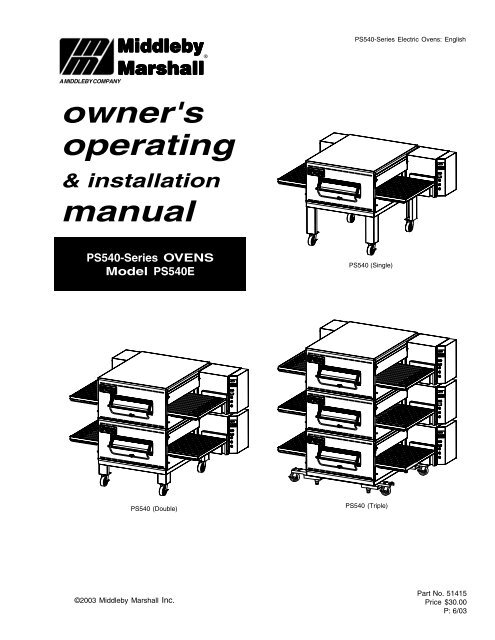
PS540-Series Electric Ovens: English<br />
owner's<br />
operating<br />
& installation<br />
manual<br />
PS540-Series OVENS<br />
Model PS540E<br />
PS540 (Single)<br />
PS540 (Double)<br />
PS540 (Triple)<br />
©2003 Middleby Marshall Inc.<br />
Part No. 51415<br />
Price $30.00<br />
P: 6/03
WARNING<br />
FOR YOUR SAFETY, DO NOT STORE OR USE<br />
GASOLINE OR OTHER FLAMMABLE VAPORS AND<br />
LIQUIDS IN THE VICINITY OF THIS OR ANY OTHER<br />
APPLIANCE.<br />
WARNING<br />
Improper installation, adjustment, alteration, service, or<br />
maintenance can cause property damage, injury, or<br />
death. Read the installation, operation, and maintenance<br />
instructions thoroughly before installing or servicing this<br />
equipment.<br />
NOTICE<br />
The warranty is NOT VALID unless the oven is installed, started, and<br />
demonstrated under the supervision of a factory-authorized installer.<br />
NOTICE<br />
Contact your authorized Service Agency to perform maintenance and<br />
repairs. A Service Agency Directory is supplied with your oven.<br />
NOTICE<br />
Using any parts other than genuine Middleby Marshall factory-manufactured<br />
parts relieves the manufacturer of all warranty and liability.<br />
NOTICE<br />
Middleby Marshall (Manufacturer) reserves the right to<br />
change specifications at any time.<br />
KEEP THIS MANUAL IN A VISIBLE LOCATION NEAR THE OVEN<br />
FOR FUTURE REFERENCE.<br />
ii
Model No.<br />
Modéle No.<br />
Serial No.<br />
Serié No.<br />
Installation Date<br />
Date d'installation<br />
MIDDLEBY MARSHALL<br />
NO QUIBBLE LIMITED WARRANTY<br />
(U.S.A. ONLY)<br />
MIDDLEBY MARSHALL, HEREINAFTER REFERRED TO AS<br />
“THE SELLER”, WARRANTS EQUIPMENT MANUFACTURED<br />
BY IT TO BE FREE FROM DEFECTS IN MATERIAL AND<br />
WORKMANSHIP FOR WHICH IT IS RESPONSIBLE. THE<br />
SELLER’S OBLIGATION UNDER THIS WARRANTY SHALL<br />
BE LIMITED TO REPLACING OR REPAIRING, AT SELLER’S<br />
OPTION, WITHOUT CHARGE, ANY PART FOUND TO BE<br />
DEFECTIVE AND ANY LABOR AND MATERIAL EXPENSE<br />
INCURRED BY SELLER IN REPAIRING OR REPLACING<br />
SUCH PART. SUCH WARRANTY SHALL BE LIMITED TO<br />
THE ORIGINAL PURCHASER ONLY AND SHALL BE EFFEC-<br />
TIVE FOR A PERIOD OF ONE YEAR FROM DATE OF ORIGI-<br />
NAL INSTALLATION, OR 18 MONTHS FROM DATE OF PUR-<br />
CHASE, WHICHEVER IS EARLIER, PROVIDED THAT TERMS<br />
OF PAYMENT HAVE BEEN FULLY MET.<br />
This warranty is valid only if the equipment is installed, started,<br />
and demonstrated under the supervision of a factory-authorized<br />
installer.<br />
Normal maintenance functions, including lubrication, cleaning,<br />
or customer abuse, are not covered by this no quibble<br />
warranty.<br />
Seller shall be responsible only for repairs or replacements<br />
of defective parts performed by Seller’s authorized service<br />
personnel. Authorized service agencies are located in principal<br />
cities throughout the contiguous United States, Alaska,<br />
and Hawaii. This warranty is valid in the 50 United States<br />
and is void elsewhere unless the product is purchased<br />
through Middleby International with warranty included.<br />
The foregoing warranty is exclusive and in lieu of all other<br />
warranties, expressed or implied. There are no implied<br />
warranties of merchantability or of fitness for a particular<br />
purpose.<br />
The foregoing shall be Seller’s sole and exclusive obligation<br />
and Buyer’s sole and exclusive remedy for any action, including<br />
breach of contract or negligence. In no event shall<br />
Seller be liable for a sum in excess of the purchase price of<br />
the item. Seller shall not be liable for any prospective or lost<br />
profits of Buyer.<br />
This warranty is effective on Middleby Marshall equipment<br />
sold on, or after, February 15, 1995.<br />
MIDDLEBY MARSHALL INC.<br />
OVEN LIMITED WARRANTY<br />
(Non U.S.A.)<br />
The Seller warrants equipment manufactured by it to be free from<br />
defects in material and workmanship for which it is responsible. The<br />
Seller’s obligation under this warranty shall be limited to replacing or<br />
repairing, at Seller’s option, without charge, F.O.B. Seller’s factory,<br />
any part found to be defective and any labor and material expense<br />
incurred by Seller in repairing or replacing such part. Such warranty<br />
is limited to a period of one year from date of original installation or<br />
15 months from date of shipment from Seller’s factory, whichever is<br />
earlier, provided that terms of payment have been fully met. All labor<br />
shall be performed during regular working hours. Overtime premium<br />
will be charged to the Buyer.<br />
This warranty is not valid unless equipment is installed, started,<br />
and demonstrated under the supervision of a factory-authorized<br />
installer.<br />
Normal maintenance functions, including lubrication, adjustment of<br />
airflow, thermostats, door mechanisms, microswitches, burners<br />
and pilot burners, and replacement of light bulbs, fuses and indicating<br />
lights, are not covered by warranty.<br />
Any repairs or replacements of defective parts shall be performed by<br />
Seller’s authorized service personnel. Seller shall not be responsible<br />
for any costs incurred if the work is performed by other than<br />
Seller’s authorized service personnel.<br />
When returning any part under warranty, the part must be intact and<br />
complete, without evidence of misuse or abuse, freight prepaid.<br />
Seller shall not be liable for consequential damages of any kind<br />
which occur during the course of installation of equipment, or which<br />
result from the use or misuse by Buyer, its employees or others of<br />
the equipment supplied hereunder, and Buyer’s sole and exclusive<br />
remedy against Seller for any breach of the foregoing warranty or<br />
otherwise shall be for the repair or replacement of the equipment or<br />
parts thereof affected by such breach.<br />
The foregoing warranty shall be valid and binding upon Seller if and<br />
only if Buyer loads, operates and maintains the equipment supplied<br />
hereunder in accordance with the instruction manual provided to<br />
Buyer. Seller does not guarantee the process of manufacture by<br />
Buyer or the quality of product to be produced by the equipment<br />
supplied hereunder and Seller shall not be liable for any prospective<br />
or lost profits of Buyer.<br />
THE FOREGOING WARRANTY IS EXCLUSIVE AND IN LIEU OF<br />
ALL OTHER EXPRESS AND IMPLIED WARRANTIES WHATSO-<br />
EVER. SPECIFICALLY THERE ARE NO IMPLIED WARRANTIES<br />
OF MERCHANTABILITY OR OF FITNESS FOR A PARTICULAR<br />
PURPOSE.<br />
The foregoing shall be Seller’s sole and exclusive obligation and<br />
Buyer’s sole and exclusive remedy for any action, whether in breach<br />
of contract or negligence. In no event shall seller be liable for a sum<br />
in excess of the purchase price of the item.<br />
© 2003 - Middleby Marshall, A Middleby Company.<br />
The Middleby Marshall logo is a registered trademark of Middleby Marshall, A Middleby Company.<br />
Middleby Marshall Inc. • 1400 Toastmaster Drive • Elgin, Illinois 60120-9272 U.S.A. • (847) 741-3300 • FAX: (847) 741 4406<br />
iii
TABLE OF CONTENTS<br />
Page<br />
SECTION 1<br />
I. MODEL IDENTIFICATION .............................................. 1<br />
SERIES PS540 ELECTRICAL SPECIFICATIONS ............. 2<br />
II. PRINCIPLE OF AIR FLOW ............................................. 3<br />
A. Heat Transfer and How It Works .............................. 3<br />
II. PRINCIPLE OF AIR FLOW (Continued) ........................ 4<br />
B. Air Fingers ................................................................. 4<br />
III. COMPONENT FUNCTION ............................................ 5<br />
A. Conveyor Motor and Conveyor Belt ........................ 6<br />
B. Blower Fan ................................................................. 6<br />
C. Electric Heaters ........................................................ 6<br />
D. Window ....................................................................... 6<br />
E. Cooling Fan ................................................................ 7<br />
F. Air Fingers and Blank Plates - See Figure 1-9 ......... 8<br />
SECTION 2<br />
I. UNLOADING ................................................................... 9<br />
PS540 OVEN INSTALLATION<br />
REQUIRED KITS AND EQUIPMENT ........................ 10<br />
PARTS LIST FOR SERIES PS540 ELECTRIC OVEN<br />
INSTALLATION KIT .................................................. 10<br />
PARTS LIST FOR PS540 SERIES SINGLE OVEN<br />
OPTION - BASE W/15″ LEGS & TOP P/N 34832 ..... 11<br />
PARTS LIST FOR PS540 SERIES DOUBLE OVEN<br />
OPTION - BASE W/6″ LEGS,<br />
CASTERS & TOP P/N 34833 .................................... 12<br />
PARTS LIST FOR PS540 SERIES TRIPLE OVEN<br />
OPTION - BASE w/OUTRIGGERS & TOP<br />
P/N 34831 ................................................................... 13<br />
RESTRAINT CABLE INSTALLATION .......................... 16<br />
UTILITY ROUGH-IN DIMENSIONS AND POSITIONING<br />
FOR PS540-SERIES OVENS .................................... 17<br />
CIRCUIT BREAKER ..................................................... 17<br />
ELECTRICAL SPECIFICATIONS ................................. 17<br />
ELECTRICAL RATING ................................................. 17<br />
SUPPLY WIRE .............................................................. 17<br />
SUGGESTED ................................................................ 17<br />
II. VENTILATION GUIDELINES .................................... 18<br />
VENTILATION HOOD ................................................... 18<br />
VENTILATION CAPTURE TEST ................................... 18<br />
III. ELECTRICAL CONNECTION INFORMATION FOR<br />
PS540-SERIES OVENS. ........................................... 19<br />
IV. ELECTRIC SUPPLY FOR ELECTRIC-HEATED<br />
OVENS ...................................................................... 19<br />
V. CONVEYOR REAR STOP AND<br />
END STOP INSTALLATION ...................................... 20<br />
SECTION 3 INSTALLATION<br />
I. CONTROL FUNCTIONS ................................................ 21<br />
II. COMPONENT INFORMATION AND LOCATION ......... 22<br />
A. Door Safety Switch .................................................. 22<br />
B. Blower Switch .......................................................... 22<br />
C. Heat Switch .............................................................. 22<br />
D. Temperature Controller .......................................... 22<br />
E. Conveyor ................................................................. 23<br />
MEASURING CONVEYOR SPEED. ............................. 23<br />
III. STEP-BY-STEP OPERATION ..................................... 24<br />
A. Startup Procedures ................................................. 24<br />
TABLE OF CONTENTS<br />
(Continued)<br />
Page<br />
Daily Startup ................................................................. 24<br />
Power Failure ............................................................... 24<br />
B. Shutdown Procedure ............................................... 24<br />
A.Daily Startup Procedure .......................................... 26<br />
IV. NORMAL OPERATION - STEP-BY-STEP .................. 26<br />
V. QUICK REFERENCE: TROUBLESHOOTING ............. 28<br />
SECTION 4 MAINTENANCE<br />
I. MAINTENANCE - DAILY ........................................... 30<br />
A. Exterior .................................................................... 30<br />
B. Cooling Fan .............................................................. 30<br />
C. Conveyor Belt ......................................................... 30<br />
D. Crumb Pans ............................................................ 30<br />
E. Window .................................................................... 30<br />
II. MAINTENANCE - MONTHLY ...................................... 31<br />
A. Removing Conveyor From Oven For Cleaning .... 31<br />
B. Air Fingers Disassembly For Cleaning ................. 33<br />
C. Cleaning the Window .............................................. 34<br />
D. Reassembly of Air Fingers .................................... 34<br />
E. Reinstall End Plugs ................................................. 37<br />
F. Conveyor Reassembly Into Oven .......................... 38<br />
G. Checking Conveyor Belt Tension ......................... 38<br />
H. Conveyor Belt Link Removal ................................ 39<br />
I. Replacing Conveyor Belt ......................................... 40<br />
J. Attaching Drive Chain ............................................ 40<br />
III. MAINTENANCE - EVERY 3 MONTHS ........................ 41<br />
A. Cleaning the Blower/Fan Motor ............................. 41<br />
B. Electrical Terminals ............................................... 42<br />
C. Ventilation ............................................................... 42<br />
D. Checking the Blower/Fan Belt ............................... 42<br />
E. Blower Fan Shaft Bearing Lubrication .................. 43<br />
F. Split-belt Conveyor Shaft Cleaning ........................ 43<br />
IV. MAINTENANCE - EVERY 6 MONTHS .................... 44<br />
PS540-SERIES ELECTRIC OVEN KEY SPARE<br />
PARTS ...................................................................... 46<br />
KEY SPARE PARTS KIT .............................................. 46<br />
SECTION 5 TROUBLESHOOTING<br />
Troubleshooting Charts ..................................................... 47<br />
SECTION 6 - PARTS LIST<br />
OVEN PANELS, WINDOW AND LEGS ............................ 51<br />
CONTROL PANEL ........................................................... 53<br />
BLOWER AND SHROUD ................................................. 55<br />
CONVEYOR ...................................................................... 57<br />
SPLIT BELT CONVEYOR ................................................. 59<br />
MACHINERY COMPARTMENT ....................................... 61<br />
SECTION 7 ELECTRICAL SCHEMATICS<br />
Wiring Diagram, E208-240 50/60, 3PH 4W PS540 ........ 63<br />
Wiring Diagram, E380-480 50/60, 3PH 5W PS540 ........ 64<br />
Wiring Diagram, E380V 50/60, 3PH 5W PS540 .............. 65<br />
NOTE<br />
Wiring Diagrams are in Section 7 of this Manual.<br />
The diagram for each oven is also on the lower<br />
inner surface of its Control Console.<br />
iv
SECTION 1<br />
DESCRIPTION<br />
SECTION 1<br />
DESCRIPTION<br />
I. MODEL IDENTIFICATION<br />
The Middleby Marshall PS540-Series may be used either<br />
as a single oven or stacked for use as double or triple<br />
ovens. The major difference between the oven models in<br />
this series is the width of the conveyor.<br />
A single PS540-Series Oven (Figure 1-1) is mounted on a<br />
base pad with legs and casters. A double oven (Figure 1-2)<br />
consists of two, stacked, single ovens. A triple oven<br />
(Figure 1-3) consists of three stacked single ovens. The<br />
lower oven is mounted on a base pad with short legs and<br />
casters.<br />
On a double or triple oven, the ovens operate completely<br />
independent. All ovens use identical controls and components.<br />
One oven can be cleaned or serviced, while the<br />
others are operating.<br />
Figure 1-1. Single PS540 Oven<br />
Figure 1-2. Double PS540 Oven<br />
Figure 1-3. Triple PS540 Oven<br />
1
SECTION 1<br />
DESCRIPTION<br />
PS540 SERIES OVEN SPECIFICATIONS<br />
Conveyor Belt Width<br />
Heating Zone Length<br />
Baking Area Square Feet<br />
32″ (813mm)<br />
40-1/2″ (1028mm)<br />
9 sq. ft. (0.84 sq. m.)<br />
Overall Dimension<br />
Standard Single Oven w/Legs 80″ (2032mm) L ×<br />
61-5/16″ (1557mm) W ×<br />
47-5/16″ (1202mm) H ×<br />
Overall Dimension<br />
Double Oven 80″ (2032mm) L ×<br />
61-5/16″ (1557mm) W ×<br />
60-15/16″ (1548mm) H x<br />
Overall Dimension<br />
Triple Oven<br />
Weight of Single Oven<br />
Shipping Weight<br />
80″ (2032mm) L x<br />
61-5/16″ (1557mm) W ×<br />
77-1/2″ (1969mm) H ×<br />
925 lb (419kg)<br />
1,100 lb (498.3kg)<br />
Shipping Cube Approx. 132 ft 3 (3.74 m 3 )<br />
Operating Range<br />
Maximum Operating Temperature<br />
Warm-up Time<br />
Recirculating Air Fan<br />
Air Velocity<br />
Bake Time<br />
27 kW/hr<br />
550°F (287°C)<br />
15 min.<br />
One fan at 2300 RPM<br />
3000 fpm (1524 cm/sec) (Average)<br />
3 min. 0 sec. Bake Time minimum<br />
30 min. 0 sec. Bake Time maximum<br />
SERIES PS540 ELECTRICAL SPECIFICATIONS<br />
Main Blower & Control Circuit Phase Frequency Amperage Poles Wires<br />
Elements Voltage Voltage Draw<br />
208-240V 208-240V 3 Ph 50/60 Hz 100 Amp 4 Pole 4 Wire<br />
(3 hot, 1 grd)<br />
HEATER AMPERAGE<br />
Voltage kW Amp Average Amps<br />
208 27 75 37 37 37<br />
240 27 65 33 33 33<br />
308V Export 208-240V 3 Ph 50/60 Hz 50 Amp 4 Pole 5 Wire<br />
(3 hot, 1neut, 1 grd)<br />
HEATER AMPERAGE<br />
Voltage kW Amp Average Amps<br />
380 27 41 22 22 22<br />
480V 208-240V 3 Ph 50/60 Hz 50 Amp 4 Pole 5 Wire<br />
(3 hot, 1neut, 1 grd)<br />
HEATER AMPERAGE<br />
Voltage kW Amp Average Amps<br />
480 27 32.5 28 28 28<br />
NOTE<br />
Wiring Diagrams are contained in Section 7 of this Manual<br />
and are also located inside the oven at the<br />
bottom of the Control Panel<br />
This Manual Must Be Kept For Future Reference<br />
2
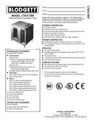
II. PRINCIPLE OF AIR FLOW<br />
The fan-style blower draws air into the oven plenum where<br />
it is heated. The blower then pushes the hot air through the<br />
air fingers into the baking chamber. Each air finger<br />
contains an inner plate and outer plate that form the hot air<br />
into jets, distributing it across a conveyor belt on which the<br />
food product rides. Air is then pulled back into the blower<br />
and the process continues. The curving, black arrows of<br />
Figure 1-4 show this air flow.<br />
A. Heat Transfer and How It Works<br />
1. Heat constantly moves from a warm object to a cold<br />
object. Heat moves using three different paths: Conduction;<br />
Radiation; and Convection.<br />
Conduction: This path utilizes surface-to-surface contact.<br />
The pizza dough in contact with the pan is a good<br />
example of conduction.<br />
Radiation: This path has to do with objects radiating heat.<br />
Dark objects absorb heat whereas light or shiny objects<br />
SECTION 1<br />
DESCRIPTION<br />
reflect more heat. This is the reason that the inside of a<br />
PS540-Series Oven is light in color: To reflect more heat<br />
back onto the food product.<br />
Convection: This path has to do with moving a volume of<br />
air. It explains why hot air rises and cooler air replaces hot<br />
air. An industrial application of this principle is to incorporate<br />
a fan to force the hot air movement, which in turn<br />
increases the heat transfer to the food product.<br />
Each PS540-Series Oven has a large fan-style blower to<br />
move the hot air through the air fingers and onto the<br />
product to cook/bake the food product most efficiently.<br />
2. Temperature is the intensity of heat at the point where<br />
it is sensed. As discussed above, heat flows by conduction,<br />
radiation and convection. The speed at which the heat<br />
flows is determined by the temperature difference between<br />
the oven and the food product. The larger the difference,<br />
the faster the heat flows to the item that is being baked.<br />
Upper Air Fingers<br />
Conveyor Belt(s)<br />
Window<br />
Lower Air Fingers<br />
Figure 1-4. PS540-Series Oven Air Flow<br />
3
SECTION 1<br />
DESCRIPTION<br />
II. PRINCIPLE OF AIR FLOW (Continued)<br />
B. Air Fingers<br />
The PS540-Series Ovens are conveyorized ovens that<br />
employ vertical jets of hot air streaming from air fingers<br />
(Figure 1-5) to give uniform, intense heating. The vertical<br />
streams of hot air provide an exceptional heat transfer rate<br />
and generally bake faster and at lower temperatures than<br />
convection hot air or infrared heating ovens.<br />
A PS540-Series Oven can accommodate up to four<br />
bottom air fingers and four top air fingers. Some PS540-<br />
Series ovens used to bake pizza have four bottom fingers<br />
and two top fingers. For special product baking requirements,<br />
a number of other styles of fingers and finger<br />
arrangements are available from the factory.<br />
NOTE: Some customers have a predetermined finger<br />
arrangement. If you have any questions pertaining to the<br />
finger arrangement, please call the factory.<br />
Manifold<br />
Air Flow<br />
From Plenum<br />
Manifold Baffle<br />
Outer Plate<br />
Inner Plate<br />
High Velocity<br />
Columns of Air<br />
on Food Product<br />
Air Flow<br />
From Plenum<br />
Manifold Baffle<br />
Inner Plate<br />
Manifold<br />
Outer Plate<br />
Figure 1-5. Air Fingers, Showing High-Velocity Columns of Air Formed During Passage Through<br />
the Inner Plate and Outer Plate to Heat the Food Product.<br />
4
III. COMPONENT FUNCTION (Figure 1-6)<br />
SECTION 1<br />
DESCRIPTION<br />
Figure 1-6. PS540-Series Oven Components Locations<br />
5
SECTION 1<br />
DESCRIPTION<br />
III. COMPONENT FUNCTION<br />
A. Conveyor Motor and Conveyor Belt<br />
The conveyor belt is driven by a variable-speed electric<br />
motor (Figure 1-7) operating through a gear reducer. The<br />
motor speed is controlled by a digital control. The stainless-steel<br />
wire belt can travel in either direction at variable<br />
rates ranging from 3 minutes to 30 minutes; this is the time<br />
that a product can take to pass through the oven.<br />
B. Blower Fan<br />
The blower fan is located at the rear of the oven. This<br />
blower forces heated air through the air fingers. The<br />
BLOWER switch must be set to “ON” or “I” for oven<br />
warmup and baking.<br />
C. Electric Heaters<br />
There are six heater elements mounted on the inside of the<br />
rear panel. Each element is connected to an electrical<br />
control which is energized by the temperature controller.<br />
D. Window<br />
A window on the front of the oven permits viewing the items<br />
being baked and provides access to the oven for items that<br />
do not require full baking time, such as sandwiches,<br />
cookies, small items, or cheese-melting processes.<br />
E. Cooling Fan — See Figure 1-8<br />
The cooling fans are located in the back of the oven.<br />
These cooling fans draw air through its grille, blowing it<br />
through the blower motor compartment and the control<br />
compartment into the oven top and exhausted out the front<br />
louvers.<br />
Left Control Box<br />
F. Air Fingers and Blank Plates - See Figure 1-9<br />
F1. Air Fingers<br />
An Air Finger Assembly is made up of three parts:<br />
1. Outer Plate - The Outer Plate is the removable covering<br />
with tapered holes, which direct the air stream onto the<br />
product being baked.<br />
2. Inner Plate -The perforated Inner Plate is vital in forming<br />
the unique air jets. It must be assembled into the manifold<br />
with its holes aligned with the holes of the outer plate.<br />
3. Manifold - The Manifold is the assembly which slides<br />
on tracks into the oven plenum.<br />
Right Control Box<br />
Figure 1-7. Machinery Compartment<br />
Components<br />
6
SECTION 1<br />
DESCRIPTION<br />
Cooling Fan Grille<br />
Figure 1-8. Cooling Fan<br />
7
SECTION 1<br />
DESCRIPTION<br />
F2. Blank Plates<br />
1. Blank Plates- The Blank Plates are available to install<br />
on the plenum where an air finger is not required.<br />
Half Blank Plate<br />
Outer Plate<br />
Blank Plate<br />
Inner Plate<br />
Finger<br />
Manifold<br />
Assembly<br />
Baffle<br />
Figure 1-9. Blank Plates (two sizes) and an Air Finger.<br />
8
SECTION 2<br />
INSTALLATION<br />
SECTION 2<br />
INSTALLATION<br />
NOTE: The oven, when installed, must be electrically<br />
grounded in accordance with local codes, or in the absence<br />
of local codes, with the National Electrical Code<br />
(NEC), or ANSI/NFPA70.<br />
NOTE<br />
There must be adequate clearance between<br />
the oven and any adjacent combustible construction.<br />
Clearance must also be provided<br />
for servicing and for operation.<br />
CAUTION<br />
It is required that the oven be placed under a<br />
ventilation hood for adequate air supply and<br />
ventilation.<br />
CAUTION<br />
Do not obstruct the flow of combustion and<br />
ventilation air to and from your oven. Do not<br />
obstruct the ventilation holes in the Control Panel.<br />
CAUTION<br />
On ovens with the Machinery Drive Compartment<br />
located at the right end, a minimum clearance of<br />
0″ to a left side wall, 18″ to a right side wall and 6″<br />
from a back wall to air openings at the rear of the<br />
oven must be maintained. On ovens with the<br />
machinery/drive compartment located at the left<br />
end, a minimum clearance of 0″ to a right side<br />
wall, 18″ to a left side wall and 6″ from a back wall<br />
to air openings at the rear of the oven must be<br />
maintained.<br />
For servicing and cleaning, a minimum of 18″<br />
clearance from all walls is recommended.<br />
I. UNLOADING<br />
Your Middleby Marshall PS540-Series Oven is shipped<br />
partially assembled. It will arrive in a carton on a crate.<br />
Carton size for a PS540-Series Oven is:<br />
84″ (2134mm) Long ×<br />
58″ (1473mm) Wide ×<br />
44″ (1118mm) High ×<br />
The crate and carton must be examined before signing the<br />
Bill of Lading. Report any visible damage to the transport<br />
company, and check for the proper number of crates. If<br />
apparent damage is found, make arrangements to file a<br />
claim against the carrier. Surface Interstate Commerce<br />
Regulations (U.S.A.) require that the claim must be<br />
initiated by the consignee within 10 days from the date that<br />
the shipment is received.<br />
A Pre-installation Procedures Manual (MM P/N 88910-0009)<br />
is attached to the exterior wall of the carton. This manual<br />
contains detailed instructions on unpacking and moving the<br />
oven(s) to the operating site. When the transport company<br />
notifies you of an impending delivery, arrange to have a forklift<br />
at your facility to unload the carton(s).<br />
Instructions for stacking the ovens is continued in a<br />
separate manual used by Middleby Marshall Authorized<br />
Installers.<br />
If you have a door wider than the carton, simply move the<br />
carton into your facility and arrange an appointment with<br />
your Middleby Marshall Authorized Installer.<br />
If your door is narrower than the carton, then the oven will<br />
have to be unpacked. Follow the directions shown in the<br />
Pre-Installation Procedures Manual.<br />
9
SECTION 2<br />
INSTALLATION<br />
PS540 OVEN INSTALLATION<br />
REQUIRED KITS AND EQUIPMENT<br />
TYPE PS540 PS540 Single PS540 Double PS540 Triple<br />
OF Electric Oven Oven Option Oven Option Oven Option<br />
INSTALLATION Installation Base w/15″ Legs, Base w/6″ Legs, Base w/Casters<br />
Kit P/N Casters & Top Casters & Top & Top<br />
48810-0008 Kit P/N Kit P/N Kit P/N<br />
34832 34833 34831<br />
PS540 Single Oven 1 1<br />
PS540 Double Oven 2 1<br />
PS540 Triple Oven 3 1<br />
PARTS LIST FOR SERIES PS540 ELECTRIC OVEN<br />
INSTALLATION KIT<br />
P/N 48810-0008<br />
(Two required for double oven)<br />
(Three required for triple oven)<br />
ITEM<br />
NO. QTY PART NO. DESCRIPTION<br />
1 1 33900-0032 CONVEYOR WIRE BELT<br />
2 1 35000-1103 CONVEYOR END STOP<br />
3 1 35900-0148 CONVEYOR LEFT REAR STOP<br />
4 1 50664 SERIES PS540 OWNER/OPERATOR MANUAL<br />
5 1 1002040 SERVICE AGENCY DIRECTORY<br />
1<br />
2<br />
3<br />
4<br />
5<br />
Figure 2-1. PS540-Series Electric Oven<br />
Installation Parts<br />
10
SECTION 2<br />
INSTALLATION<br />
Figure 2-2. Model PS540 Single Oven<br />
Option Base with Legs and Top<br />
PARTS LIST FOR PS540 SERIES SINGLE OVEN OPTION - BASE w/15″ LEGS & TOP<br />
P/N 34832<br />
ITEM<br />
NO. QTY PART NO. DESCRIPTION<br />
1 1 37900-0025 COMPLETE BASE WELDMENT<br />
2 4 37900-0024 TOP PLATE, LEG WELDMENT<br />
3 2 22290-0009 SWIVEL CASTER W/BRAKE FLAT PLATE<br />
4 2 22290-0010 SWIVEL CASTER FLAT PLATE<br />
5 32 220373 3/8″-16 × 1″ HEX SCREW,SST<br />
6 32 21416-0001 3/8″ FLAT WASHER, SS<br />
7 32 21422-0001 3/8″ SPLIT LOCK WASHER, ZP<br />
8 4 21256-0008 SCREWS FOR TOP 10-32 × 3/8″ 18-8, SL TRUS S<br />
9 1 22450-0228 RESTRAINT CABLE ASSEMBLY<br />
10 1 33486 TOP COVER 304 PANEL<br />
11
SECTION 2<br />
INSTALLATION<br />
Figure 2-3. Model PS540 Double Oven<br />
Option Base with Legs and Top<br />
PARTS LIST FOR PS540 SERIES DOUBLE OVEN OPTION - BASE w/6″ LEGS, CASTERS & TOP<br />
P/N 34833<br />
ITEM<br />
NO. QTY PART NO. DESCRIPTION<br />
1 1 37900-0025 COMPLETE BASE WELDMENT<br />
2 4 37900-0102 TOP PLATE, LEG WELDMENT<br />
3 2 22290-0009 SWIVEL CASTER W/BRAKE FLAT PLATE<br />
4 2 22290-0010 SWIVEL CASTER FLAT PLATE<br />
5 32 220373 3/8″-16 × 1″ HEX SCREW,SST<br />
6 32 21416-0001 3/8″ FLAT WASHER, SS<br />
7 32 21422-0001 3/8″ SPLIT LOCK WASHER, ZP<br />
8 4 21256-0008 SCREWS FOR TOP 10-32 × 3/8″ 18-8, SL TRUS S<br />
9 1 22450-0228 RESTRAINT CABLE ASSEMBLY<br />
10 1 33486 TOP COVER 304 PANEL<br />
12
SECTION 2<br />
INSTALLATION<br />
Figure 2-4. Model PS540 Triple Oven<br />
Option Base with Outriggers and Top<br />
PARTS LIST FOR PS540 SERIES TRIPLE OVEN OPTION - BASE w/CASTERS & TOP<br />
P/N 34831<br />
ITEM<br />
NO. QTY PART NO. DESCRIPTION<br />
1 1 37900-0025 COMPLETE BASE WELDMENT<br />
2 4 45209 QUAD OUTRIGGER WELDMENT<br />
3 2 22290-0009 SWIVEL CASTER, W/BRAKE FLAT PLATE<br />
4 2 22290-0010 SWIVEL CASTER, FLAT PLATE<br />
5 4 45206 INSERT,QUAD ADJUSTMENT FOOT<br />
6 4 45205 SPACER,QUAD CASTER<br />
7 32 220373 3/8″-16 × 1″ HEX BOLT, SST<br />
8 32 21416-0001 3/8″ FLAT WASHER, SS<br />
9 32 21422-0001 3/8″ SPLIT LOCK WASHER, ZP<br />
10 16 21172-0004 3/8″-16 NYLON INSULATED LOCKNUT, ZC<br />
11 8 21216-0018 1/2″-13 × 1-1/4″ 18-8 HEX CAPSCREW<br />
12 8 21416-0003 1/2″ 18-8 FLAT WASHER<br />
13 8 21426-0004 1/2″ 18-8 LOCK WASHER<br />
14 4 21256-0008 SCREWS FOR TOP 10-32 × 3/8″ 18-8, SL TRUS S<br />
15 1 22450-0228 RESTRAINT CABLE ASSEMBLY<br />
16 1 33486 TOP COVER 304 PANEL<br />
13
SECTION 2<br />
INSTALLATION<br />
Figure 2-5. MODEL PS540 SINGLE OVEN DIMENSIONS<br />
2<br />
1<br />
Conduit for Electrical Connections<br />
2<br />
2<br />
2<br />
RECOMMENDED MINIMUM CLEARANCES:<br />
Rear of Oven to Wall - 6″ (150mm)<br />
Non-control End of Oven to Wall - 0″<br />
Control End of Oven to Wall - 0″<br />
1<br />
14
SECTION 2<br />
INSTALLATION<br />
Figure 2-6. MODEL PS540 DOUBLE OVEN DIMENSIONS<br />
1<br />
Conduit for Electrical Connections<br />
2<br />
2<br />
2<br />
2<br />
RECOMMENDED MINIMUM CLEARANCES:<br />
Rear of Oven to Wall - 6″ (150mm)<br />
Non-control End of Oven to Wall - 0″<br />
Control End of Oven to Wall - 0″<br />
1<br />
15
SECTION 2<br />
INSTALLATION<br />
Figure 2-7. MODEL TRIPLE OVEN DIMENSIONS<br />
1<br />
Conduit for Electrical Connections<br />
2<br />
2<br />
2<br />
2<br />
RECOMMENDED MINIMUM CLEARANCES:<br />
Rear of Oven to Wall - 6″ (150mm)<br />
Non-control End of Oven to Wall - 0″<br />
Control End of Oven to Wall - 0″<br />
1<br />
RESTRAINT CABLE INSTALLATION<br />
Install the restraint cable assembly on the oven, as shown<br />
in Figure 2-6.<br />
Figure 2-8. Restraint Cable Assembly Installation<br />
16
UTILITY ROUGH-IN DIMENSIONS AND POSITIONING<br />
FOR PS540-SERIES OVENS<br />
SECTION 2<br />
INSTALLATION<br />
WARNING<br />
DO NOT USE CONDUIT OR GAS LINE<br />
FOR GROUND CONNECTION.<br />
To Oven<br />
ON<br />
OFF<br />
CAUTION<br />
IT IS REQUIRED THAT THE OVEN BE<br />
PLACED UNDER A VENTILATION<br />
HOOD FOR ADEQUATE AIR SUPPLY<br />
AND VENTILATION.<br />
To Oven<br />
ON<br />
OFF<br />
24"<br />
610mm<br />
24"<br />
610mm<br />
ELECTRIC SUPPLY TO BE<br />
PROVIDED BY CUSTOMER<br />
Suggested dimensions are shown; utility code<br />
requirements supersede any factors shown.<br />
CIRCUIT BREAKER<br />
Separate circuit breaker with lockout/tagout electrical<br />
shutoff for each oven. Wire each oven separately.<br />
100 Amp circuit breaker for 200-240V, or 50 Amp circuit<br />
breaker for 380-480V.<br />
ELECTRICAL SPECIFICATIONS<br />
DOMESTIC: 208V main blower motors and elements,<br />
3 Ph, 75 Amp draw, 50/60 Hz, 208-240V control circuit,<br />
3 pole, 4 wire system per oven (3 hot, 1 grd).<br />
Do NOT use conduit for ground.<br />
or<br />
DOMESTIC: 240V main blower motors and elements,<br />
3 Ph, 65 Amp draw, 50/60 Hz, 208-240V control circuit,<br />
3 pole, 4 wire system per oven (3 hot, 1 grd).<br />
Do NOT use conduit for ground.<br />
or<br />
EXPORT: 380V elements, 3 Ph, 41 Amp draw, 50/60 Hz,<br />
208-240V control circuit and main blower motor, 4 pole,<br />
5 wire system per oven (3 hot, 1 neutral, 1 grd).<br />
Do NOT use conduit for ground.<br />
or<br />
EXPORT: 480V elements, 3 Ph, 32.5 Amp draw,<br />
50/60 Hz, 208-240V control circuit and main blower motor,<br />
4 pole, 5 wire system per oven (3 hot, 1 neutral, 1 grd).<br />
Do NOT use conduit for ground.<br />
Figure 2-9. Typical PS540-Series Oven(s)<br />
Installation<br />
ELECTRICAL RATING<br />
27 kW/hr.<br />
SUPPLY WIRE<br />
Supply wire size must be a minimum of #8 AWG (10 2 mm)<br />
and must be in compliance with local codes.<br />
NOTE: The electrical terminal connection marked “MP”<br />
located inside the control compartment is designated for<br />
the blue (neutral) wire to the oven. See the electrical wiring/<br />
schematics in Section 7 of this manual.<br />
SUGGESTED<br />
If space permits, service should be located near the<br />
control console end of the oven(s) to allow convenient<br />
access to safety switches.<br />
17
SECTION 2<br />
INSTALLATION<br />
II. VENTILATION GUIDELINES<br />
A mechanically driven ventilation system is required for<br />
the PS540 Series Middleby Marshall conveyorized electric<br />
ovens. The minimum hood canopy dimensions are<br />
outlined below.<br />
Local codes and conditions vary greatly from one area to<br />
another and must be complied with. Following are the<br />
suggested requirements for good ventilation. Please remember<br />
these are recommendations or guidelines, you<br />
may have a special condition or problem that will require<br />
the services of a ventilation engineer or specialist. Proper<br />
ventilation is the oven owner’s responsibility. Improper<br />
ventilation can inhibit oven performance. It is recommended<br />
that the ventilation and duct work be checked out<br />
every three months. Grease filters in the intake of the hood<br />
may be required by local codes.<br />
VENTILATION HOOD<br />
The rate of air flow exhausted through the ventilation<br />
system is generally between 1400 and 2500 cu. ft./min. (40<br />
and 70 m 3 /min), but may vary depending on the oven<br />
configuration and hood design. To avoid a negative pressure<br />
condition in the kitchen area, return air must be<br />
brought back to replenish the air that was exhausted. A<br />
negative pressure in the kitchen can cause heat related<br />
problems to the oven components as if there were no<br />
ventilation at all. The best method of supplying return air<br />
is through the heating, ventilation and air conditioning<br />
system. Through they system, the air can be temperature<br />
controlled for summer and winter. Return air can be<br />
brought in directly from outside the building, but detrimental<br />
affects can result from either extreme seasonal hot and<br />
cold temperature from the outdoors.<br />
NOTE: Return air from fan driven system within the hood<br />
must not blow at opening of bake chamber or poor oven<br />
baking performance will result.<br />
VENTILATION CAPTURE TEST<br />
It is recommended that a 30 second smoke candle test be<br />
performed on your ventilation hood system. Follow the<br />
steps below to complete the ventilation smoke test.<br />
All tests are to be done on single ovens or lower units of<br />
a double or triple oven. We recommend you wear<br />
protective gloves when performing this test. At no time<br />
should food be present when the smoke test is being<br />
conducted. Also check that no fire suppression system<br />
will be activated by the smoke.<br />
1. Turn ventilation system on.<br />
2. Turn oven(s) on and allow to heat up to customers<br />
normal operating temperature, or a minimum of<br />
480°F (248°C).<br />
3. Turn conveyor off. Place a 30 second smoke candle in<br />
a pie or cake pan which is no higher than 3″ (76mm).<br />
4. Open the front oven window. Next, light the smoke<br />
candle in the pan and then slide the pan into the center of<br />
the bake chamber on the conveyor belt and close the<br />
window.<br />
5. The ventilation hood should capture 90% to 100% of the<br />
smoke produced by the candle.<br />
2″ (51mm)<br />
minimum.<br />
To allow<br />
stacking of<br />
ovens.<br />
21-1/2″<br />
(546mm)<br />
minimum<br />
18″<br />
(458mm)<br />
minimum<br />
8″ (203mm)<br />
minimum<br />
1″ (25mm)<br />
minimum<br />
Figure 2-10. Vent Hood<br />
18
III. ELECTRICAL CONNECTION<br />
INFORMATION FOR PS540-SERIES<br />
OVENS.<br />
WARNING<br />
Authorized supplier personnel normally accomplish<br />
the connections for the ventilation system,<br />
electric supply, and gas supply, as arranged by<br />
the customer. Following these connections, the<br />
factory-authorized installer can perform the initial<br />
startup of the oven.<br />
Check the oven data plate (Figure 2-11) before making any<br />
electric supply connections. Electric supply connections<br />
must agree with data on the oven data plate.<br />
NOTE: The electric supply installation must satisfy the<br />
requirements of the appropriate statutory authority, such<br />
as the National Electrical Code (NEC), ANSI/NFPA70,<br />
(U.S.A.); the Canadian Electrical Code, CSA C22.2; the<br />
Australian Code AG601; or other applicable regulations.<br />
A fused disconnect switch or a main circuit breaker<br />
(customer furnished) MUST be installed in the electric<br />
supply line for each oven; it is recommended that this<br />
switch/ circuit breaker have lockout/tagout capability. The<br />
electric supply connection must meet all national and local<br />
electrical code requirements. Copper is the recommended<br />
material for the electrical supply conductors.<br />
SECTION 2<br />
INSTALLATION<br />
IV. ELECTRIC SUPPLY FOR<br />
ELECTRICALLY HEATED OVENS<br />
Power requirements for electrically heated ovens are<br />
usually 208 - 240VAC, 3-phase, 4-wire (3 ‘hot’, 1 ground),<br />
although ovens built for export can have power requirements<br />
of 380VAC and 480VAC. (These ovens have a<br />
5-wire system.) A 2″ (51mm) diameter cutout/hole in the<br />
back of the machiney compartmenet provides access for<br />
the electrical supply connections. Using flexible cable(s)<br />
for the electrical power supply conductors requires a 2″<br />
(51mm) strain-relief fitting (not furnished) to enable safe<br />
access to the terminal block from which oven power is<br />
distributed.<br />
The supply conductors must be of the size and material<br />
(copper) recommended to provide the current required;<br />
(refer to the data plate for the ampere specifications). The<br />
electric current rating for each conductor supplying a<br />
PS540-Series Oven ranges from a minimum of 95 amperes<br />
to a maximum of 100 amperes.<br />
Typical specifications for each PS540-Series Oven are<br />
208V or 240V, 3-phase, 4-wire, 100-ampere, 27kW; this<br />
oven requires 100-ampere service. A PS540-Series Double<br />
Oven (Figure 1-2) installation would require two<br />
100-ampere service connections, one for each oven; the<br />
27kW power consumption also doubles for such an<br />
installation to 54kW.<br />
The 208V or 240VAC electrically heated oven uses two<br />
legs of the supplied power to provide 208V or 240VAC<br />
power for the oven control circuitry.<br />
Electrical Junction<br />
Cover Plate<br />
Figure 2-11. Typical Electric Oven Data Plate<br />
Figure 2-12. Junction Connection Box<br />
19
SECTION 2<br />
INSTALLATION<br />
V. CONVEYOR REAR STOP AND END<br />
STOP INSTALLATION<br />
Locate the conveyor rear stop and end stop in the<br />
installation kit. Install the rear stop and end stop at the exit<br />
end of the oven. See Figure 2-13.<br />
Conveyor Rear Stop<br />
Conveyor End Stop<br />
Middleby<br />
Marshall<br />
Figure 2-13. Installing Rear and End Stops<br />
20
SECTION 3<br />
OPERATION<br />
SECTION 3<br />
OPERATION<br />
I. CONTROL FUNCTIONS<br />
Figure 3-1. PS540-Series Oven Control Functions<br />
WARNING<br />
A possibility of injury from rotating parts and<br />
electric shock exists in this oven.<br />
Never disassemble or clean the oven with the<br />
BLOWER switch or any other oven control turned<br />
“ON” or “I”. Turn “OFF” or “O” and lockout or<br />
tagout all electric power to the oven before<br />
attempting to clean or service this oven.<br />
21
SECTION 3<br />
OPERATION<br />
II. COMPONENT INFORMATION AND<br />
LOCATION (Figures 3-1 and 3-2)<br />
A. Door Safety Switch<br />
The Door Safety Switch is located at the lower left side of<br />
control panel opening. Opening the control panel door<br />
permits this switch to open, disconnecting power to all<br />
electrical controls.<br />
CAUTION<br />
Do NOT touch the wires going to this safety switch.<br />
Current is always present.<br />
B. Blower Switch<br />
The blower switch has two positions. The switch must be<br />
“ON” or “I” for the burner to come on and permit the oven<br />
to warm up. The fan circulates the air throughout the oven<br />
and must stay on during baking and during the cool down<br />
cycle above 200°F (93°C) to prevent blower bearing<br />
damage. To protect the blower motor and bearings a<br />
thermostatic override is built into the oven. If the temperature<br />
inside the oven is over 180°F (82°C) the main blower<br />
will continue to run after the blower switch is turned to the<br />
“OFF” or “O” position.<br />
An air pressure switch monitors the air flow from the<br />
blower, acting as a safety interlock for the heater. The<br />
heaters will not function, if the air switch does not sense<br />
air flow off the main blower fan.<br />
C. Heat Switch<br />
Turning the HEAT switch to “ON” or“I” will energize the<br />
electric heating system. This switch is in series with the<br />
blower fan motor and high temperature override switch.<br />
Both switches must be closed before the heating elements<br />
an be energized.<br />
D. Temperature Controller<br />
The temperature controller is a solid-state, PID type to<br />
maintain the operator-set temperature. The temperature<br />
controller continuously monitors the oven temperature and<br />
turns on the modulating solid state relay controller. The<br />
heat is on for the time required to maintain a constant oven<br />
temperature.<br />
The temperature controller contains a low-limit switch<br />
which allows the oven to cool down to 200°F (93°C) before<br />
shutting off the blower. A high-limit indication (ALM 1) will<br />
appear on the display if the oven reaches 650°F (343°C).<br />
Figure 3-2. Interior View of Machinery Compartment and Control Console<br />
22
E. Conveyor<br />
The on-off switch for the conveyor motor is on the control<br />
panel. Also on the control panel is the digital conveyor<br />
speed control. The digital control can be adjusted from 3<br />
min. to 30 min. bake time (conveyor speed). Refer to<br />
Figure 3-3.<br />
Conveyor speed is measured by the amount of time it<br />
takes for an item to go through the bake chamber of the<br />
oven.<br />
MEASURING CONVEYOR SPEED.<br />
See Figures 3-4 and 3-5.<br />
To check conveyor speed, place a product item at the<br />
entrance end of baking chamber as shown. Time how long<br />
it takes for the leading edge of the item to go from the<br />
entrance end of the baking chamber to the exit end. This<br />
should be the conveyor speed shown on the conveyor<br />
speed digital control.<br />
NOTE: In Figures 3-4 and 3-5, the oven shown is with the<br />
conveyor running right to left.<br />
WARNING<br />
Possibility of injury from rotating parts and<br />
electrical shock exist in this oven.<br />
Never disassemble or clean the oven with the<br />
blower switch or any other part of the oven<br />
turned “ON” or “I”. Turn “OFF” or “O” and<br />
lockout or tagout all electrical power to the<br />
oven before attempting to clean or service<br />
this oven.<br />
SECTION 3<br />
OPERATION<br />
Figure 3-3. Conveyor Speed Digital Control<br />
Figure 3-4. Product at entrance end of baking<br />
chamber – BEGINNING OF TIMING<br />
Figure 3-5. Product at exit end of baking<br />
chamber – END OF TIMING<br />
23
SECTION 3<br />
OPERATION<br />
WARNING<br />
OVEN MUST BE KEPT CLEAR OF<br />
COMBUSTIBLES AT ALL TIMES.<br />
III. STEP-BY-STEP OPERATION<br />
Control Panel (On split belt ovens, two conveyor speed<br />
controls are mounted on the control panel.)<br />
A. Startup Procedures<br />
Daily Startup<br />
1. Turn the BLOWER switch (Figure 3-6) to the “ON” or “I”<br />
position. This starts the main blower fan and the cooling<br />
fans. The blower circulates air through the air fingers and<br />
must stay on during the cooking or baking process.<br />
2. Check to see if the cooling fans (see Figure 1-8) are<br />
operating when the blower switch (see Figure 3-6) is turned<br />
“ON” or “I”. The cooling fans cool the control components<br />
and blower motor. The cooling fans, located at the rear of<br />
the electrical control cabinet blows air into and through the<br />
cabinet. Air is exhausted through the front of the cabinet<br />
and also out the front of the oven. Refer to Daily Maintenance<br />
Section for fan intake checking procedure.<br />
IMPORTANT NOTE<br />
The cooling fan operates when the BLOWER<br />
switch is turned “ON” or “I”. It must operate to keep<br />
the control console below 140°F (60°C).<br />
4. Set the temperature controller to the desired baking<br />
temperature. See section on bake times to determine<br />
desired temperature.<br />
NOTE: For complete temperature controller operation<br />
instructions refer to Step C.<br />
5. Turn the HEAT switch (Figure 3-6) to the “ON” or “I”<br />
position. This completes a circuit to supply electric power<br />
to the electric heating system.<br />
6. Close front window.<br />
7. Oven will reach a baking temperature of 500°F (232°C)<br />
in approximately 15 minutes. Allow the oven to cycle for<br />
30 minutes after it has reached desired bake temperatue.<br />
The oven is now ready for baking.<br />
Power Failure<br />
In case of power failure, turn off all switches; open oven<br />
window and remove product. After power has been<br />
reestablished follow normal startup procedure.<br />
B. Shutdown Procedure<br />
1. Turn the BLOWER and HEAT switches to “OFF” or “O”.<br />
NOTE: The blowers will remain on until the oven temperature<br />
cools down to 200°F (93°C) at which time they will stop<br />
automatically.<br />
2. Make certain that there are no products left on the<br />
conveyor inside the oven. Turn the CONVEYOR switch<br />
to “OFF” or “O”.<br />
3. Open the oven window.<br />
3. Turn the CONVEYOR switch (Figure 3-6) to the “ON” or<br />
“I” position. This starts the conveyor belt moving through<br />
the oven. Set the conveyor speed for the desired baking<br />
time. Refer to the following Procedures E, F and G.<br />
24
SECTION 3<br />
OPERATION<br />
Figure 3-6. Control Panel<br />
25
SECTION 3<br />
OPERATION<br />
II. NORMAL OPERATION - STEP-BY-STEP<br />
A.Daily Startup Procedure<br />
1. Check that the circuit breaker/fused disconnect is in the<br />
on position. Check that the window is closed.<br />
2. Turn the "BLOWER"<br />
( ) switch to the “ON”<br />
("I") position.<br />
3. Turn the "CONVEYOR"<br />
( ) switch to the<br />
“ON” ("I") position.<br />
7. Wait for the oven to heat to the setpoint temperature.<br />
Higher setpoint temperatures will require a longer wait.<br />
The oven can reach a temperature of 500°F (232°C) in<br />
approximately 15 minutes.<br />
8. (Optional) Press the Temperature<br />
( ) key to show<br />
the Actual Temperature<br />
in the display, and wait<br />
for the "ACTUAL TEMP"<br />
light to turn on. This allows<br />
you to monitor the<br />
oven temperature as it<br />
rises to the setpoint.<br />
wait<br />
for<br />
9. Allow the oven to preheat for 10 minutes after it has<br />
reached the set point temperature.<br />
4. If necessary, adjust the<br />
conveyor speed setting<br />
by pressing the or<br />
pushbuttons on the conveyor<br />
speed controller to<br />
change the displayed<br />
bake time.<br />
5. Adjust the temperature<br />
controller to a desired set<br />
temperature, if necessary.<br />
• Press the Set Point<br />
and Unlock keys at<br />
the same time. Wait<br />
for the "SET PT" light<br />
to turn on.<br />
+<br />
or<br />
wait<br />
for<br />
B. DAILY SHUTDOWN PROCEDURE<br />
1. Turn the "HEAT" ( ) and<br />
"BLOWER" ( ) switches<br />
to the "OFF" ("O")<br />
position. Note that the<br />
blowers will remain in operation<br />
until the oven has<br />
cooled to below 200°F<br />
(93°C).<br />
2. Make certain that there<br />
are no products left on<br />
the conveyor inside the<br />
oven. Turn the "CON-<br />
VEYOR" ( ) switch to<br />
the "OFF" ("O") position.<br />
+<br />
• Press the Up Arrow<br />
and Down Arrow<br />
Keys as necessary<br />
to adjust the setpoint.<br />
or<br />
3. Open the window to allow the oven to cool faster.<br />
4. After the oven has cooled and the blowers have turned<br />
to the “OFF” or “O” position, switch the circuit breaker/fuse<br />
disconnect to the “OFF” or “O” position.<br />
6. Turn the "HEAT" ( )<br />
switch to the "ON" ("I")<br />
position, and wait for the<br />
"HEAT ON" light to turn<br />
on.<br />
wait<br />
for<br />
CAUTION<br />
In case of power failure, turn all switches to the “OFF”<br />
("O") position, open the oven window, and remove<br />
the product. After the power has been restored,<br />
perform the normal startup procedure. IF THE OVEN<br />
WAS SWITCHED OFF FOR LESS THAN 5 MINUTES,<br />
WAIT FOR AT LEAST FIVE MINUTES BEFORE RE-<br />
STARTING THE OVEN.<br />
26
SECTION 3<br />
OPERATION<br />
"SP LOCK"<br />
Light<br />
Lights when the<br />
set point is locked<br />
out from changes.<br />
This setting can<br />
only be changed by<br />
service personnel.<br />
Display<br />
Shows the Set Point<br />
or the Actual Temperature<br />
in degrees<br />
Fahrenheit (F) or<br />
Celsius (C).<br />
"HEAT ON"<br />
Light<br />
Lights when the<br />
burner is in<br />
operation.<br />
"SET PT"<br />
(setpoint)<br />
Light<br />
Lights when the<br />
set point is shown<br />
in the display.<br />
OVERTEMP<br />
Light<br />
Lights when the oven<br />
temperature is<br />
greater than 650°F<br />
(343°C). Refer to<br />
Quick Reference:<br />
Troubleshooting in<br />
this section.<br />
"ACTUAL TEMP"<br />
Light<br />
Lights when the Actual<br />
Temperature is shown<br />
in the display.<br />
Temperature<br />
Key<br />
Press this key once<br />
to view the Actual<br />
Temperature in the<br />
Display.<br />
Service Key<br />
Service use<br />
only.<br />
Unlock Key<br />
Press this key<br />
together with the Set<br />
Point Key to allow the<br />
Set Point to be<br />
changed. Changes<br />
can only be made for<br />
60 seconds.<br />
Up Arrow and Down<br />
Arrow Keys<br />
Press these keys to<br />
adjust the Set Point up or<br />
down. If the Set Point will<br />
not change, refer to Set<br />
Point Key and Unlock Key<br />
in this section.<br />
Set Point Key<br />
Press this key<br />
together with the<br />
Unlock Key to allow<br />
the Set Point to be<br />
changed.<br />
Changes can only be<br />
made for 60 seconds.<br />
27
SECTION 3<br />
OPERATION<br />
IV. QUICK REFERENCE: TROUBLESHOOTING<br />
SYMPTOM PROBLEM SOLUTION<br />
light is lit, food product is<br />
undercooked<br />
Oven will not<br />
turn on at all<br />
The oven temperature exceeded<br />
650°F (343°C), and<br />
the burner was automatically<br />
shut down.<br />
Electrical power may not be<br />
reaching the oven, or the<br />
controls may be set incorrectly.<br />
• Follow the procedures under Daily Shutdown Procedures in<br />
this section to shut down the oven. Contact your Middleby<br />
Marshall Authorized Service Agent to determine and correct the<br />
cause of the condition to prevent damage to the oven.<br />
• Check that the circuit breaker/fused disconnect is turned on.<br />
• Check that the "BLOWER" ( ) Switch is in the “ON” ("I")<br />
position.<br />
appears in display,<br />
oven is not heating<br />
The oven did not reach<br />
200°F (93°C) within 15 minutes<br />
of startup, and the oven<br />
has stopped heating.<br />
• Turn the "HEAT" ( ), "BLOWER" ( ), and "CONVEYOR"<br />
( )switches to the "OFF" ("O") position.<br />
• Wait for AT LEAST FIVE MINUTES before restarting the oven.<br />
• Repeat the Daily Startup procedure.<br />
Oven will not heat<br />
Controls may be set incorrectly.<br />
• Check that the Set Point is correctly set.<br />
• Check that both the "BLOWER" ( ) and "HEAT" ( ) Switches<br />
are in the “ON” ("I") position.<br />
• If the oven still will not heat,turn the "HEAT" ( ), "BLOWER"<br />
( ), and "CONVEYOR" ( )switches to the "OFF" ("O")<br />
position.<br />
• Wait for AT LEAST FIVE MINUTES before restarting the oven.<br />
• Repeat the Daily Startup procedure. Check that the Set Point<br />
is above 200°F (93°C).<br />
Oven is operating, but<br />
little or no air is blowing<br />
from air fingers<br />
Air fingers may have been<br />
reassembled incorrectly<br />
after cleaning.<br />
• Turn the oven to the “OFF” or “O” position, and allow it to cool.<br />
Disconnect electrical power to the oven.<br />
• Refer to Section 4, Maintenance, for instructions on reassembling<br />
the air fingers.<br />
Conveyor moves with a<br />
jerky motion, or will not<br />
move at all<br />
Conveyor may be jammed<br />
on an object in the oven, or<br />
conveyor belt or drive chain<br />
tension may be incorrect.<br />
• Turn the oven to the “OFF” or “O” position, and allow it to cool.<br />
Disconnect electrical power to the oven.<br />
• Check if the conveyor is blocked by an object inside the oven.<br />
• Refer to Section 4, Maintenance, for instructions on checking<br />
the conveyor and drive chain tension.<br />
Food products are<br />
overcooked or<br />
undercooked.<br />
Controls may be set incorrectly.<br />
• Check that the set temperature and bake time settings are<br />
correct.<br />
IF THESE STEPS FAIL TO RESOLVE THE PROBLEM, CONTACT YOUR LOCAL MIDDLEBY MARSHALL<br />
AUTHORIZED SERVICE AGENT. A SERVICE AGENCY DIRECTORY IS SUPPLIED WITH YOUR OVEN.<br />
28
SECTION 4<br />
MAINTENANCE<br />
SECTION 4<br />
MAINTENANCE<br />
WARNING<br />
Possibility of injury from rotating parts and electrical<br />
shock exist in this oven. Turn off and lockout or tagout<br />
electrical supply to oven(s) before attempting to<br />
disassemble, clean or service oven(s). Never disassemble<br />
or clean the oven with the blower switch or any<br />
other part of the oven turned on.<br />
WARNING<br />
Before performing any maintenance work or cleaning,<br />
turn main power switch off.<br />
CAUTION<br />
When cleaning do not use any abrasive cleaning<br />
materials or water spray, wipe clean only. Never use a<br />
water hose or pressurized steam cleaning equipment<br />
when cleaning this oven.<br />
NOTICE<br />
If the oven is to be removed from its installed location<br />
for servicing, perform the following procedure:<br />
1. Switch off the oven and allow it to cool. Do NOT<br />
service the oven while it is warm.<br />
2. Turn off main circuit breakers and disconnect<br />
connector from oven.<br />
3. Turn the adjustable legs to put weight on the<br />
casters.<br />
4. Move oven to desired location for servicing.<br />
5. When servicing is complete, move oven to original<br />
location.<br />
6. Adjust legs to level oven and take weight off<br />
casters.<br />
7. Connect electrical connectors to oven.<br />
8. Turn on main circuit breakers.<br />
9. Follow normal startup instructions.<br />
29
SECTION 4<br />
MAINTENANCE<br />
I. MAINTENANCE - DAILY<br />
A. Exterior<br />
Everyday you should clean the outside of the oven with a<br />
soft cloth and mild detergent.<br />
WARNING<br />
Never use a water hose or pressurized steam<br />
cleaning equipment when cleaning the oven.<br />
D. Crumb Pans (Figure 4-2)<br />
Remove and clean the crumb pan at each end of the oven.<br />
Each crumb pan can be removed by sliding it out, as<br />
shown in Figure 4-2. Reinstall the crumb pans after<br />
cleaning.<br />
E. Window<br />
The window can be cleaned daily while it is in place.<br />
Vent Grille<br />
B. Cooling Fan<br />
1. FOUR COOLING FAN GRILLES AT THE REAR OF<br />
EACH OVEN CONTROL COMPARTMENT MUST BE<br />
CLEANED DAILY - Clean grilles with a stiff nylon type<br />
brush.<br />
2. Check the air intake of the cooling fan daily. The best<br />
time to check is right after starting the oven.<br />
Cooling Fan Grille<br />
IMPORTANT NOTE<br />
The cooling fan operates when the blower switch<br />
is turned to “ON” (“I”). It must operate to keep the<br />
electrical control cabinet below 140°F (60°C).<br />
Cooling Fan Grille<br />
WARNING<br />
IF FAN BLADE IS NOT ROTATING, BROKEN,<br />
OR FAN ASSEMBLY IS MISSING FROM MAIN<br />
BLOWER MOTOR SHAFT, DO NOT OPERATE<br />
OVEN. REPLACE COOLING FAN BLADE<br />
BEFORE OPERATING OVEN. Serious damage<br />
could be done to the burner blower motor and/or<br />
solid-state electrical components if oven is<br />
operated while cooling fan is not running or vent<br />
grille is plugged.<br />
Figure 4-1. Oven Cooling Fans<br />
3. Using a stiff nylon brush clean control compartment<br />
vent grille. Hot air from control compartment exits from this<br />
grille.<br />
C. Conveyor Belt (Figure 4-2)<br />
Everyday, just after starting the oven, stand at the<br />
unloading end of the conveyor, and with a brush, remove<br />
food particles (crumbs, etc.) clinging to the conveyor belt,<br />
brushing them into the crumb pan.<br />
Figure 4-2. Conveyor Belt and<br />
Crumb Pan Cleaning<br />
30
II. MAINTENANCE - MONTHLY<br />
NOTE: The oven interior may require cleaning more<br />
than once a month depending on the volume of<br />
baking. To clean the interior, you have to disassemble<br />
some parts of the oven.<br />
When cleaning your Series PS540 Oven note the<br />
following:<br />
PRECAUTIONS-<br />
1. Do not use excessive water or saturation of oven<br />
insulation will occur.<br />
2. Do not use a caustic oven cleaner or the aluminized<br />
finger manifold surfaces will be severely damaged.<br />
When cleaning your oven, first remove all heavy debris<br />
with a vacuum cleaner. Use a damp cloth for light cleaning.<br />
For heavier cleaning of baked on grease and carbon<br />
SECTION 4<br />
MAINTENANCE<br />
deposits use a non-caustic cleaner that will not react with<br />
the aluminized finger manifold surfaces.<br />
You can order non-caustic cleaner from your local authorized<br />
Middleby Marshall Parts Distributor in the quantities<br />
listed below:<br />
Part #<br />
Quantity<br />
27170-0244 Case of Quarts (6)<br />
27170-0246 Case of Gallons (4)<br />
A. Removing Conveyor From Oven For Cleaning<br />
1. Remove crumb pans as shown in Figure 4-2.<br />
2. Remove upper and lower end plugs from each end of<br />
oven by removing the two wing screws from each end plug.<br />
3. Remove the conveyor end stop and the conveyor rear<br />
stop (Figure 4-3).<br />
Figure 4-3.<br />
31
SECTION 4<br />
MAINTENANCE<br />
4. Remove conveyor drive chain cover as shown.<br />
5. Remove tension from drive chain by lifting and pushing<br />
the conveyor slightly into the oven. Remove drive chain<br />
from conveyor drive sprocket as shown.<br />
NOTE: The split belt conveyor assembly can only be<br />
removed from the drive end of the oven.<br />
6. Begin sliding conveyor out of the oven as shown.<br />
Figure 4-4.<br />
Figure 4-7.<br />
7. Continue sliding the conveyor completely out of the<br />
oven, fold it in half and then place it to the side for cleaning.<br />
Be careful not to bump drive sprocket while handling<br />
conveyor or damage may result to drive shaft.<br />
Figure 4-5.<br />
Figure 4-8.<br />
CAUTION<br />
Be careful not to bump the drive sprocket while<br />
handling the conveyor, to avoid damaging the<br />
drive shaft.<br />
Figure 4-6.<br />
32
B. Air Fingers Disassembly For Cleaning<br />
1. As the air fingers are removed use a felt pen to mark all<br />
parts of the fingers. This includes the finger manifold, inner<br />
plate and the outer plate (refer to Figure 1-9). If a blank or<br />
choke plate is used, mark that plate also. Fingers are<br />
marked in the order shown; as viewed from the front of the<br />
oven. (The marks for an upper oven should be preceded<br />
with a “U”, example UB1, UT2, etc.)<br />
SECTION 4<br />
MAINTENANCE<br />
T1 T2 T3 T4<br />
B1 B2 B3 B4<br />
Standard Fingers<br />
2. Slide blank plates straight out.<br />
Figure 4-10.<br />
4. With air fingers out, place them in an upright position to<br />
remove the outer plate.<br />
5. Gently step o the lip of the finger and pull the outer plate<br />
off.<br />
Figure 4-9.<br />
3. Remove air fingers.<br />
NOTE: Some oven users require a custom finger arrangement<br />
where the quantity of air fingers may vary.<br />
You can remove top and bottom fingers and blank plates<br />
from each or either end. It is highly recommended that<br />
each finger be marked before removing so it is placed in<br />
exactly the same position when reassembled<br />
(refer to step 1).<br />
Remove the air fingers, pull the finger at the back side - pull<br />
straight out.<br />
Figure 4-11.<br />
33
SECTION 4<br />
MAINTENANCE<br />
6. To remove the inner plate, pull the plate out and then up.<br />
1. Remove the window by opening the window and unscrewing<br />
the window knobs from each end.<br />
Figure 4-12.<br />
7. The outer finger plate is stainless and may be cleaned<br />
by either soaking in a hot, strong detergent solution or<br />
using a caustic cleaner. The conveyor belt can also be<br />
cleaned in the same way.<br />
Figure 4-15.<br />
2. Push the window all the way inside the oven, making<br />
sure it is clear of the frame. Now, turn the window sideways<br />
while inside the oven and then remove it. This will avoid<br />
breaking the window.<br />
Figure 4-16.<br />
Figure 4-13. Standard Lower Finger<br />
D. Reassembly of Air Fingers<br />
1. Air fingers are made up of one inner plate, one outer<br />
plate and the finger housing manifold. Be sure to match up<br />
the markings (T1, T2, T3, etc.) on all the parts of the air<br />
fingers as you are reassembling.<br />
Figure 4-14. Standard Upper Finger<br />
C. Cleaning the Window<br />
The window can be cleaned in place. If it needs a thorough<br />
cleaning it may have to be removed.<br />
34<br />
Figure 4-17.
2. Reassemble the inner plate. Keep your fingers clear so<br />
you won’t pinch them. The inner plate of a finger will only<br />
go in one way because of its design.<br />
3. Replace the outer plate by placing your hands flat on<br />
the top of the plate and pushing down. Keep your fingers<br />
clear so you won’t pinch them.<br />
SECTION 4<br />
MAINTENANCE<br />
Figure 4-19.<br />
Figure 4-18.<br />
4. Replace the air fingers by pushing in at the back side.<br />
Remember to replace them according to the numbers<br />
marked on them when they were removed. They must go<br />
back in the same way they came out.<br />
IMPORTANT: Only M6 Fingers fit in the bottom<br />
row. All M3 and M1 finger cover plates have<br />
extended lips at front. This extended lip will not<br />
allow these fingers to be installed in the bottom row.<br />
IMPORTANT: When inserting fingers the tab on<br />
the outer plate must be in the groove as shown in<br />
Figure 4-20. There is a blocking tab on the outside<br />
of the groove which will prevent inserting the<br />
finger in the groove if the outer plate is moved<br />
away from the flange of the finger manifold.<br />
Extended Lip<br />
Tab on<br />
Outer Plate<br />
Flange of<br />
Finger Manifold<br />
Tab on<br />
Outer Plate<br />
Figure 4-20.<br />
35
SECTION 4<br />
MAINTENANCE<br />
5. Install fingers and blank plates correctly with edges<br />
interlocked and no space between edges.<br />
Top Finger<br />
Incorrect - Too<br />
Much Space<br />
Blank Plate<br />
Tab on Outer Plate of Finger<br />
Located in Groove<br />
Top Finger<br />
Incorrect - Too<br />
Much Space<br />
Blank Plate<br />
Tab on Outer Plate of Finger<br />
Located in Groove<br />
Top Finger<br />
Correct -<br />
Edges Overlap<br />
Completely<br />
Blank Plate<br />
Tab on Outer Plate of Finger<br />
Located in Groove<br />
Figure 4-21.<br />
36
E. Reinstall End Plugs<br />
1. Reinstall lower end plug. Be sure to tighten two wing<br />
screws on the end plug.<br />
2. Reinstall conveyor.<br />
3. Reinstall upper end plug. Be sure to tighten two wing<br />
screws on the end plug.<br />
SECTION 4<br />
MAINTENANCE<br />
Figure 4-22.<br />
Figure 4-23.<br />
37
SECTION 4<br />
MAINTENANCE<br />
F. Conveyor Reassembly Into Oven<br />
1. Lift conveyor and position it in oven as shown.<br />
NOTE: Conveyor assembly may be inserted into either<br />
end of oven. If it is to be installed from the non-drive end<br />
of the oven the drive sprocket assembly must be removed<br />
as shown in conveyor disassembly section.<br />
NOTE: Split belt conveyors can only be inserted from the<br />
drive end of the oven.<br />
G. Checking Conveyor Belt Tension<br />
WARNING<br />
Oven conveyor belt must be cool when adjusting<br />
belt. Do not adjust belt if HOT.<br />
1. With the conveyor assembly in the oven, stand at one<br />
end of conveyor and check tension by lifting the conveyor<br />
belt at the center of the oven chamber opening. The belt<br />
should not lift higher that 3″ to 4″ (75mm to 102mm).<br />
2. Adjust conveyor belt tension screws (located on left<br />
end of oven) for the 3″ to 4″ (75mm to 102mm) deflection<br />
as shown in Figure 4-26. If there is proper tension, proceed<br />
to “J. Attaching Drive Chain”. If belt is still too loose,<br />
continue to step 3 below.<br />
3. If conveyor belt is still not under proper tension, an<br />
entire link must be removed. Use the following procedure<br />
“H. Conveyor Belt Link Removal” to remove a link. If<br />
conveyor belt is under proper tension proceed directly to<br />
“J. Attaching Drive Chain”.<br />
Figure 4-24.<br />
2. Reinstall the conveyor rear stop. Reinstall the conveyor<br />
end stop.<br />
Conveyor Rear Stop<br />
Conveyor End Stop<br />
Middleby<br />
Marshall<br />
Figure 4-26.<br />
Figure 4-25.<br />
38
H. Conveyor Belt Link Removal<br />
1. Using long nose pliers, an entire link can be removed<br />
with the conveyor assembly either in or out of the oven.<br />
Position master links at end of conveyor as shown in<br />
Figure 4-27.<br />
SECTION 4<br />
MAINTENANCE<br />
4. Unhook the link to be removed.<br />
5. Pull up on the belt link section and remove. Do not<br />
discard the link removed as it may be used for making<br />
spare master links.<br />
NOTE: If a section of the conveyor belt is being replaced<br />
it should be done now. Remove the links that need<br />
replacing and use the section of conveyor belt furnished in<br />
your installation kit to replace them.<br />
Master<br />
Links<br />
Figure 4-27.<br />
2. Using long nose pliers, unhook master links at left end<br />
of conveyor as shown in Figure 4-28.<br />
Figure 4-30.<br />
NOTE: Before connecting the inside master links, notice<br />
that these links have a correct position (Figure 4-31). The<br />
link at the right is in the correct (horns up) position for<br />
inserting into the conveyor belt. The horns facing down are<br />
in the incorrect position.<br />
Correct<br />
Position<br />
Figure 4-28.<br />
3. Remove the outside master links on the right and left<br />
sides of the conveyor belt as shown in Figure 4-29.<br />
Incorrect<br />
Position<br />
Figure 4-31.<br />
Figure 4-29.<br />
39
SECTION 4<br />
MAINTENANCE<br />
6. Reconnect the inside master links (Figure 4-32.)<br />
Figure 4-32.<br />
NOTE: The outside master links have right and left sides<br />
to them. The right edge master link has an open hook<br />
facing you as shown in Figure 4-33. This will match up with<br />
the outer edges of the conveyor belt. Remember this hook<br />
travels backwards on the conveyor.<br />
I. Replacing Conveyor Belt<br />
If a section of the conveyor belt needs replacing it can be<br />
done with the conveyor assembly either in or out of the<br />
oven. The section of the conveyor belt furnished with the<br />
oven in the installation kit may then be used to replace a<br />
section. Follow the preceding procedure “H. Conveyor belt<br />
link removal” which outlines the disassembly procedure.<br />
J. Attaching Drive Chain<br />
1. If drive sprocket assembly was removed reassemble it<br />
into the conveyor drive shaft. Be sure flat on end of drive<br />
shaft aligns with set screw in conveyor shaft collar. Once<br />
in place tighten 3/32″ set screw.<br />
2. Lift conveyor and install drive chain to conveyor drive<br />
sprocket and motor sprocket.<br />
Direction of travel<br />
Figure 4-33.<br />
7. Reconnect the outside master links.<br />
8. Replace all parts removed from the oven.<br />
Figure 4-35.<br />
3. The angle plate located on the underside of the conveyor<br />
must be against the lower end plug. This is true on<br />
both sides of oven.<br />
Crumb Pan<br />
Mounting<br />
Bracket<br />
Figure 4-34.<br />
Lower End Plug<br />
Figure 4-36.<br />
40
4. Reassemble conveyor drive chain cover and then<br />
reassemble the bottom cover to the drive chain cover.<br />
Install both upper end plugs.<br />
SECTION 4<br />
MAINTENANCE<br />
III. MAINTENANCE - EVERY 3 MONTHS<br />
WARNING<br />
Shut OFF all electrical power and lock/tag out the<br />
switch before attempting maintenance work.<br />
NOTE: It is recommended that the 3-month maintenance<br />
be performed by an authorized Middleby Marshall<br />
technician.<br />
A. Cleaning the Blower/Fan Motor<br />
To gain access to the blower/fan motor, open the control<br />
cabinet door by removing the three screws. Clean the<br />
motor, the conveyor drive motor and the surrounding area,<br />
using compressed air. Thoroughly blow out the motor<br />
compartment and vents inside the motor (Figure 4-38).<br />
Failure to do this can cause premature failure of blower fan<br />
motor.<br />
Figure 4-37.<br />
CAUTION<br />
Not cleaning the blower/fan motor properly can<br />
cause premature failure.<br />
Figure 4-38.<br />
41
SECTION 4<br />
MAINTENANCE<br />
B. Electrical Terminals<br />
Open the control cabinet door by removing the three<br />
screws from the control cabinet door. Tighten all electrical<br />
control terminal screws including the electrical contactor<br />
terminal screws as shown in Figure 4-39.<br />
CAUTION<br />
Overtightening the belt will cause premature bearing<br />
failure and possible vibration problems. A spare<br />
belt is located inside the control compartment on<br />
the rear wall.<br />
3. When replacing the belt, loosen the tension adjustment<br />
bolts (Figure 4-42) on the motor mounting bracket. Next,<br />
pull back on the motor. Retighten adjustment bolts. Do not<br />
overtighten because the fan bearings may be damaged.<br />
Figure 4-39.<br />
C. Ventilation<br />
Check that the air circulation throughout the oven is not<br />
blocked and is working properly.<br />
D. Checking the Blower/Fan Belt<br />
1. Check the main blower/fan belt for proper tension and<br />
wear. To gain access,loosen the six screws (Figure 4-40)<br />
of the rear shroud and lift shroud cover up and off.<br />
2. The fan belt should deflect no less than 1″ (25mm) at<br />
the center (Figure 4-41) and have no cracks or excessive<br />
wear.<br />
Figure 4-41.<br />
Figure 4-42.<br />
Figure 4-40.<br />
42
E. Blower Fan Shaft Bearing Lubrication<br />
SECTION 4<br />
MAINTENANCE<br />
3. Remove the conveyor adjustment bolts to allow the<br />
idler brackets to swing free.<br />
CAUTION<br />
Over-greasing damages the bearing seals and<br />
accelerates grease loss, which shortens bearing<br />
life. Wipe off any excess grease on and around<br />
the bearing. Reinstall the rear shroud to allow the<br />
oven to operate<br />
Grease the two (2) main blower fan shaft bearings (Figure<br />
4-43), using a special grease (MM P/N 17110-0015 lithiumbase,<br />
high-temperature grease). ONLY ONE STROKE of<br />
a grease gun is required for each bearing.<br />
Figure 4-44.<br />
4. Drop the idler shaft assembly clear of the frame through<br />
the front frame slot.<br />
Figure 4-43.<br />
Upon completing the fan belt check (or replacement) and<br />
the bearing lubrication, reinstall the rear shroud, fastening<br />
it with six screws of the rear shroud.<br />
F. Split-belt Conveyor Shaft Cleaning<br />
It is very important that the split-belt conveyor drive and<br />
idler shafts are removed from the conveyor frame for<br />
cleaning and lubrication.<br />
Figure 4-45.<br />
5. Pull the front and rear shafts apart and apply oil to both<br />
the extended shaft and the interior of the hollow shaft.<br />
Using a rag, wipe oil off parts. Repeat until shafts are<br />
clean. Apply more oil to shafts then reassemble.<br />
CAUTION<br />
Use a turbine oil or light machine oil. DO NOT<br />
USE WD40 or similar product. These oils<br />
evaporate and cause the shafts to seize.<br />
1. Perform the conveyor removal steps described in<br />
Monthly Maintenance, paragraph “A”. After the conveyor<br />
is removed, lay it on a flat surface.<br />
2. Remove the two conveyor belts by disassembling the<br />
conveyor master links, as described in Monthly Maintenance,<br />
paragraph “H”. Then, remove the two conveyor<br />
belts by rolling them up.<br />
Figure 4-46.<br />
43
SECTION 4<br />
MAINTENANCE<br />
6. Make sure bronze washer is in between the two halves.<br />
9. Loosen the split locking collar.<br />
Figure 4-47.<br />
7. Place the idler shaft assembly back into place and<br />
reinstall the adjustment screws.<br />
Figure 4-50.<br />
10. Remove drive shafts by sliding to right then lifting the<br />
left side. Follow cleaning and lubricating procedures outlined<br />
in Steps 4-6.<br />
Figure 4-48.<br />
8. Loosen the set screw on each conveyor drive sprocket<br />
and remove sprockets.<br />
Figure 4-51.<br />
11. Reassemble conveyor drive shafts into frame, making<br />
sure nylon spacer is in place.<br />
Figure 4-49.<br />
Figure 4-52.<br />
44
12. Slide shaft assembly to right side, holding assembly<br />
in place. Slide split locking collar to the left side and<br />
tighten.<br />
13. Slide rear conveyor drive sprocket onto shaft. Tighten<br />
the set screw of this drive sprocket until it extends into the<br />
hole of the hollow shaft. It should NOT touch the inner,<br />
solid shaft. Check to see that only the rear shaft moves<br />
when the sprocket is turned. If both shafts move, you have<br />
tightened the set screw too tight. Loosen the set screw<br />
until only the rear shaft moves when the sprocket is<br />
turning.<br />
14. Insert adaptor bushing into remaining drive sprocket<br />
then place onto shaft. Make sure nylon spacer is in place.<br />
Tighten set screw making sure screw goes through slot in<br />
adaptor bushing and locks onto shaft.<br />
15. Thread conveyor belts back onto frame making sure<br />
the links will be traveling in the proper direction.<br />
16. Follow conveyor reassembly instructions in Monthly<br />
Maintenance Paragraph “F”.<br />
NOTE: It is recommended that the 6 Month Maintenance<br />
schedule be performed by a Middleby Marshall authorized<br />
service technician.<br />
IV. MAINTENANCE - EVERY 6 MONTHS<br />
A. Check brushes on D.C. conveyor motor, when worn to<br />
less than 1/10″ (2.4mm), replace the brushes.<br />
B. Clean and inspect the burner nozzle and electrode<br />
assembly. Also check your oven venting system.<br />
C. Check conveyor shaft bushings and spacers. Replace<br />
them if they are worn. See Figure 6-5, Conveyor Exploded<br />
Drawing, items 15, 30 and 31 or Figure 6-6, Split Belt<br />
Conveyor, items 19, 23, 31, 35 and 36.<br />
Figure 4-53.<br />
Figure 4-54.<br />
SECTION 4<br />
MAINTENANCE<br />
IMPORTANT NOTICES:<br />
• Installation of replacement parts requiring access<br />
to the interior of the oven is permitted only by an<br />
authorized service technician.<br />
• If there are any problems with the operation of the<br />
oven, the authorized service technician must be<br />
called.<br />
• It is suggested to obtain a service contract with a<br />
manufacturer’s authorized service technician.<br />
Figure 4-55.<br />
Figure 4-56.<br />
45
SECTION 4<br />
MAINTENANCE<br />
KEY SPARE PARTS KIT<br />
An oven can be purchased with a Key Spare Parts Kit<br />
(Figure 4-56). (The kit can be purchased when the oven is<br />
ordered, or later, from a Middleby Marshall Authorized<br />
Parts Distributor). The kit contains many of the crucial<br />
parts that can reduce serious downtime and loss of<br />
production, if a failure occurs.<br />
Replacement parts for this kit can be purchased from your<br />
Middleby Marshall Authorized Parts Distributor.<br />
PS540-SERIES ELECTRIC OVEN KEY SPARE PARTS KIT (Figure 4-56)<br />
ITEM PART NO. ENGLISH DESCRIPTION QUANTITY<br />
1 47321 Kit, Temperature Control On/Off Pid 1<br />
2 44687 Blower/Fan Motor 1<br />
3 47797 Conveyor Drive Motor 1<br />
4 37337 Conveyor Speed Control 1<br />
5 33812-3 Thermocouple 1<br />
6 44914 Controller, Power 208V/240V 1<br />
6 44568 Controller, Power 380V/480V 1<br />
7 27375-0001 Heater Element, 208V 1<br />
7 27375-0002 Heater Element, 240V 1<br />
7 27375-0003 Heater Element, 380V 1<br />
7 27375-0004 Heater Element, 480V 1<br />
6<br />
7<br />
Figure 4-56. Key Spare Parts<br />
46
SECTION 5<br />
TROUBLESHOOTING<br />
SECTION 5<br />
TROUBLESHOOTING<br />
PROBLEM:<br />
PRODUCTS ARE OVERCOOKED<br />
OR UNDERCOOKED<br />
PROBLEM:<br />
OVEN BLOWER AND CONVEYOR OPER-<br />
ATE, YET THE OVEN IS NOT HEATING<br />
Check for correct<br />
setting of conveyor<br />
speed control.<br />
Check for correct<br />
setting on temperature<br />
controller.<br />
Reset the temperature controller<br />
to a new setting (above 200°F),<br />
after turning the BLOWER switch<br />
to off for 30 seconds.<br />
Set the conveyor speed<br />
control at correct setting.<br />
Turn temperature<br />
control to correct<br />
setting.<br />
Start the oven again. If the oven still does not<br />
heat, call your Middleby Marshall Service Agency.<br />
Verify the food<br />
preparation process.<br />
If products still cook incorrectly,<br />
call your Middleby Marshall<br />
Service Agency.<br />
PROBLEM:<br />
CONVEYOR WILL NOT HOLD PROPER<br />
SPEED OR WILL NOT RUN AT ALL<br />
Check whether the conveyor is<br />
jammed on something in oven.<br />
PROBLEM:<br />
OVEN DOES NOT HEAT<br />
Check to see if both BLOWER<br />
switch and HEAT switch are in<br />
the “ON” or “I” position.<br />
Check for proper tension of conveyor drive<br />
chain and conveyor belt. Refer to Section 4 for<br />
correct procedure.<br />
Check that the conveyor<br />
drive sprocket is tight.<br />
If oven does not heat, call your<br />
Middleby Marshall Service Agency.<br />
If conveyor still does not run correctly, contact<br />
your Middleby Marshall Service Agency.<br />
PROBLEM:<br />
BLOWER MOTOR IS RUNNING, YET LITTLE<br />
OR NO AIR BLOWS FROM AIR FINGERS<br />
Air fingers reassembled incorrectly,<br />
after cleaning.<br />
PROBLEM:<br />
OVEN DOES NOT TURN ON WHEN ITS<br />
SWITCHES ARE TURNED ON<br />
Check that all electric supply switches are set to<br />
the “ON” or “I” position. Then, start the oven.<br />
Assemble air fingers correctly, after cleaning.<br />
Refer to Section 4 procedure, or call your<br />
Middleby Marshall Service Agency.<br />
If oven still will not start, contact your Middleby<br />
Marshall Service Agency.<br />
47
SECTION 5<br />
TROUBLESHOOTING<br />
NOTES<br />
48
SECTION 6 - PARTS LIST<br />
SECTION 6<br />
PARTS LIST<br />
ENGLISH<br />
49
SECTION 6<br />
PARTS LIST<br />
ENGLISH<br />
50
SECTION 6<br />
PARTS LIST<br />
OVEN PANELS, WINDOW AND LEGS<br />
ITEM QTY. P/N DESCRIPTION<br />
1 2 49947 UPPER END PLUG ASSEMBLY<br />
2 2 49946 LOWER END PLUG ASSEMBLY<br />
3 8 36452 WING NUT, PLASTIC 1/4-20<br />
4 8 45449 END PLUG MOUNTING PLATE ASSEMBLY<br />
5 16 21296-0005 SCREW, HEX WSHHD12-14 × 3/4″, SS BSD<br />
6 1 49905 CONVEYOR CHAIN COVER<br />
7 2 50637 EYEBROW<br />
8 1 33486 COVER, TOP 304 PANEL<br />
9 4 21256-0008 SCREW, 10-32 × 3/8″ 18-8 SL TRUS S<br />
10 1 37900-0103 WINDOW MOUNTING FRAME WELDMENT<br />
11 1 30285 GLASS DOOR ASSEMBLY<br />
12 1 42400-0087 WINDOW LATCH ASSEMBLY<br />
13 1 37900-0025 COMPLETE BASE WELDMENT<br />
14 4 37900-0024 LEG/TOP PLATE WELDMENT<br />
15 4 37900-0102 LEG 6″ H/TOP PLATE WELDMENT<br />
16 2 22290-0009 CASTER, SWVL W/BRAKE FLAT PLATE<br />
17 2 22290-0010 CASTER SWVL FLAT PLATE<br />
18 A/R 220373 SCREW, HEX HEAD, 3/8″ - 16 × 1″ SST<br />
19 A/R 21422-0001 WASHER, LOCK SPLIT 3/8″<br />
20 A/R 21416-0001 FLAT WASHER, 3/8″ ZP<br />
21 1 22500-0021 NAME PLATE<br />
22 1 22500-0101 INSTRUCTION LABEL<br />
23 1 22500-0041 LABEL, “CAUTION HOT SURFACE”<br />
24 16 21172-0004 NUT, 3/8″-16 NYLON INSULATED L/N ZC<br />
25 8 21416-0003 FLAT WASHER 1/2″ 18-8<br />
26 8 21426-0004 LOCK WASHER 1/2″ 18-8<br />
27 8 21216-0018 SCREW, HHCS 1/2-13 × 1-1/4″ 18-8<br />
28 4 45205 QUAD CASTER SPACER<br />
29 4 45209 QUAD OUTRIGGER WELDMENT<br />
30 4 45206 QUAD ADJUSTMENT FOOT INSERT<br />
ENGLISH<br />
51
SECTION 6<br />
PARTS LIST<br />
ENGLISH<br />
52
SECTION 6<br />
PARTS LIST<br />
CONTROL PANEL<br />
ITEM QTY. P/N DESCRIPTION<br />
1 1 47321 COMBO BURST CONTROL, 4-20Ma<br />
2 1 33812-3 THERMOCOUPLE, TYPE J SHIELDED 9.50 × 60″<br />
3 1 28041-0011 CONTACTOR, 208/240V<br />
4 3 46521 KIT, BLOWER SWITCH CONTAINS ((1) 44697, (1) 44696)<br />
5 3 44697 CONTACT BLOCK<br />
6 3 44696 SELECTOR SWITCH<br />
7 1 49888 CONTROL DOOR LABEL<br />
8 1 31504 TRANSFORMER, 230V (P)/120V (S) 200VA<br />
9 2 45036 CIRCUIT BREAKER, 240V 3A<br />
10 2 46831 CIRCUIT BREAKER, 240V 8A<br />
11 1 50610 AIR SWITCH, 0.16″ WC<br />
12 1 28021-0047 INTERLOCK SWITCH, 10A NO2P<br />
13 A/R 47797 MOTOR, GEAR 1/50HP 1350:1<br />
14 1 35145 SWITCH, PB MOLVENO 250V<br />
15 1 33983 ELECTRIC HI-LIMIT CONTROL, 240V<br />
16 1 36451 COOLING FAN, 230V AC<br />
17 2 45019 BREAKER, CKT 480VAC 63A 3 POLE<br />
18 2 44594 CONTACTOR, 230VAC COIL 85A<br />
19 2 44914 CONTROLLER, PS555EL 208-240V<br />
19 2 44568 CONTROLLER, PS555EL 380-480V<br />
20 10 33363 END, STOP ENTRELEC<br />
21 1 39258 BLOCK, TERMINAL 600V 50A 5 POLE<br />
22 1 37337 CONVEYOR SPEED CONTROL W/DIGITAL SPEED DISPLAY<br />
22A 1 37503 DIGITAL SPEED CONTROL (DISPLAY ONLY)<br />
23 2 45244 FILTER, RFI 50A/440V/3PH/50/60Hz (CE OVENS ONLY)<br />
24 2 27480-0001 BLOCK, POWER DIST 2 POLES 600V (NOT SHOWN)<br />
ENGLISH<br />
53
SECTION 6<br />
PARTS LIST<br />
ENGLISH<br />
54
SECTION 6<br />
PARTS LIST<br />
BLOWER AND SHROUD<br />
ITEM QTY. P/N DESCRIPTION<br />
1 1 51157 PULLEY, 1GRV 3.0PD AK32H<br />
2 1 48855 WELDMENT, BRG BRACKET PS540G<br />
3 22 220373 SCREW, HH 3/8″ - 16 × 1″ SS T<br />
3A A/R 17110-0017 NEVER SEIZE LUBRICANT - USED ON ITEMS 3 & 7<br />
APPLIED TO THREADS BEFORE REINSTALLING<br />
4 30 21422-0001 SPLIT LOCK WASHER 3/8″ ZP<br />
5 38 21416-0001 FLAT WASHER 3/8″ SS<br />
6 2 22072-0025 BEARING, PILLOW BLOCK 5/8″<br />
7 2 21326-0002 SCREW, HX HD GRS 3/8″ - 16 × 5-1/2″<br />
8 A/R 2000203 SCREW ,HX W/HD 10 - 32 × 3/8″ ZC<br />
9 1 48872 BACK WALL SHROUD<br />
10 1 48803 AIR INLET RING<br />
11 8 35900-0108 FAN ORIFICE STAND OFF TUBE<br />
12 1 50643 FAN DRIVE SHAFT<br />
13 1 21651-0010 KEY, SQ 3/16″ × 3/16″ × 1.00″ STL<br />
14 1 48862 AXIAL FAN, 14″ DIAMETER<br />
15 1 51110 INR/OTR BACK WELDMENT<br />
16 1 22031-0017 SPECIAL BUSHING, 5/8″ ID - 3/16″ × 3/32″ KEY<br />
17 2 35323 COUPLING, COLLAR SPLIT 5/8″ DIAMETER<br />
18 4 50271 ROLL PIN, PLN 5/32″ × 7/16″<br />
19 6 27375-0001 HEATER, TBLR COIL-208V/4500W<br />
19 6 27375-0002 HEATER, TBLR COIL-240V/4500W<br />
19 6 27375-0003 HEATER, TBLR COIL-380V/4500W<br />
19 6 27375-0004 HEATER, TBLR COIL-480V/4500W<br />
20 12 2000203 SCR, SL HX W/HD MS 10-32 × 3/8″ ZC<br />
21 1 35986 BLOCK, TERM 6-POLE 600V 85A<br />
22 2 15048801 SCR, RHM 8-32 × 1-1/4″ NP<br />
ENGLISH<br />
55
SECTION 6<br />
PARTS LIST<br />
ENGLISH<br />
56
SECTION 6<br />
PARTS LIST<br />
CONVEYOR<br />
ITEM QTY. P/N DESCRIPTION<br />
ITEM QTY. P/N DESCRIPTION<br />
1 1 47042 SINGLE CONVEYOR 80″<br />
EXCLUDES ITEMS 7, 8, 9, 12, 36 & 37<br />
2 1 22450-0225 CONVEYOR BELT,<br />
1/2P 32″ × 204″ 2.84/11 S<br />
3 1 33900-0032 CONVEYOR CHAIN, SS WIRE1 FT<br />
4 1 51380 KIT, MASTER LINK,<br />
CONTAINS ((1) 33900-0016,<br />
(4) 33900-0017, (1) 33900-0018)<br />
5 1 33900-0016 MASTER LINK - LEFT 1/2P × 32″<br />
6 1 33900-0017 MASTER LINK - MIDDLE 1/2P × 32″<br />
7 1 33900-0018 MASTER LINK - RIGHT 1/2P × 32″<br />
8 4 2001371 NUT, KEPS 10-32, ZP<br />
9 1 50265 CONVEYOR CONTROL PICKUP<br />
KIT(NOT SHOWN)<br />
10 1 49400-0050 ROLLER CHAIN ASSEMBLY, SIB<br />
19 2 22034-0003 BUSHING, FLANGE 3/4″ OD, × 5/8″ ID N/D<br />
20 2 35000-1008 SCREW, ADJ - CONVEYOR IDLER<br />
21 2 35900-0020 CONVEYOR SHAFT SUPPORT BRACKET<br />
22 2 37000-0413 IDLER WELDMENT<br />
23 1 49400-0014 IDLER SHAFT ASSEMBLY<br />
INCLUDES ITEMS 24 & 25<br />
24 12 22229-0003 CONVEYOR DRIVE SPROCKET 2.0″ OD<br />
W/SCREW<br />
25 1 35000-1011 IDLER SHAFT - CONVEYOR<br />
26 1 49400-0073 CONVEYOR FRAME ASSEMBLY - DRIVE<br />
INCLUDES ITEMS 27 & 28<br />
27 1 37900-0075 COMPLETE CONVEYOR FRAME<br />
WELDMENT - DRIVE<br />
28 1 49400-0011 DRIVE SIDE ASSEMBLY - CONVEYOR<br />
INCLUDES ITEMS 19, 21, 29, 30, 31 & 32<br />
11 1 22151-0002 SPROCKET, #35-10T-5/8″<br />
29 1 22011-0013 SHAFT COLLAR W/SCREW<br />
12 1 22151-0003 SPROCKET, #35-15T-1/2″<br />
30 1 35000-1013 DRIVE SHAFT ADAPTER<br />
13 1 49400-0074 COMPLETE FOLDING CONVEYOR ASSY<br />
INCLUDES ITEMS 14, 15, 16 & 26<br />
14 2 35900-0398 PIVOT PLATE - CONVEYOR FRAME<br />
31 2 35000-1080 NYLON SPACER 3/4″ ID 1-1/4″ OD<br />
32 1 49400-0012 DRIVE SHAFT ASSEMBLY<br />
INCLUDES ITEMS 24 & 33<br />
15 4 21176-0002 LOCKNUT, HEX SS 3/8″-16<br />
33 1 35000-1012 DRIVE SHAFT - CONVEYOR<br />
16 1 49400-0072 CONVEYOR FRAME ASSEMBLY - IDLER<br />
INCLUDES ITEMS 17 & 18<br />
17 1 37900-0071 COMPLETE CONVEYOR FRAME<br />
WELDMENT - IDLER<br />
18 1 49400-0013 IDLER SIDE ASSEMBLY - CONVEYOR<br />
INCLUDES ITEMS 19, 20, 21, 22 & 23<br />
34 1 35000-1103 STOP, SIDE END CONVEYOR EXT<br />
35 1 35900-0148 STOP, BACK SIDE CONVEYOR EXT<br />
36 2 35900-0255 CRUMB PAN W/SLOTS - CONVEYOR<br />
37 2 35900-0305 CRUMB PAN - CONVEYOR<br />
38 1 47797 MOTOR, GEAR 1/50HP 1350:1<br />
ENGLISH<br />
57
SECTION 6<br />
PARTS LIST<br />
ENGLISH<br />
58
SECTION 6<br />
PARTS LIST<br />
SPLIT BELT CONVEYOR<br />
ITEM QTY. P/N DESCRIPTION<br />
ITEM QTY. P/N DESCRIPTION<br />
1 1 50646 SPLIT CONVEYOR 50/50 80″<br />
EXCLUDES ITEMS 7, 8, 9, 12, 36 & 37<br />
2 1 22450-0226 CONVEYOR BELT, 1/2P<br />
15″ × 146″ 2.86/5 SP<br />
3 1 33900-0037 CONVEYOR CHAIN, SS WIRE1 FT<br />
4 1 51382 KIT, MASTER LINK,<br />
CONTAINS ((1) 33900-0016,<br />
(1) 33900-0017, (1) 33900-0018)<br />
5 1 33900-0016 MASTER LINK - LEFT 1/2P × 32″<br />
6 1 33900-0017 MASTER LINK - MIDDLE 1/2P × 32″<br />
7 1 33900-0018 MASTER LINK - RIGHT 1/2P × 32″<br />
8 4 2001371 NUT, KEPS 10-32, ZP<br />
9 2 50265 CONVEYOR CONTROL PICKUP<br />
KIT(NOT SHOWN)<br />
10 1 49400-0070 ROLLER CHAIN ASSEMBLY, SPB 15″<br />
11 1 49400-0051 ROLLER CHAIN ASSEMBLY, SPB 26-1/2″<br />
12 1 22159-0003 SPROCKET, #25-20T-5/8″<br />
13 1 22159-0004 SPROCKET, #25-30T-1/2″<br />
14 1 49400-0092 COMPLETE FOLDING CONVEYOR SPB<br />
ASSY INCLUDES ITEMS 15, 15, 16, 19 & 36<br />
15 2 35900-0398 PIVOT PLATE - CONVEYOR FRAME<br />
16 4 21176-0002 LOCKNUT, HEX SS 3/8″-16<br />
17 16 2229-0003 CONVEYOR DRIVE SPROCKET<br />
2.0″ OD W/SCREW<br />
18 1 49400-0093 CONVEYOR FRAME ASSEMBLY - IDLER<br />
INCLUDES ITEMS 17, 19, 20, 21, 22, 23 & 24<br />
19 1 37900-0071 COMPLETE CONVEYOR FRAME<br />
WELDMENT - IDLER<br />
20 2 22034-0003 BUSHING, FLANGE 3/4″ OD, × 5/8″ ID N/D<br />
21 2 35000-1008 SCREW, ADJ - CONVEYOR IDLER<br />
22 2 35900-0020 CONVEYOR SHAFT SUPPORT BRACKET<br />
23 2 37000-0413 IDLER WELDMENT<br />
24 1 35525 IDLER SHAFT ASSEMBLY, SPB<br />
INCLUDES ITEMS 25, 26 & 27<br />
25 2 21415-0001 FLAT WASHER, BRONZE<br />
26 1 35000-1535 REAR CONVEYOR IDLER SHAFT, SPB<br />
27 1 42400-0354 FRONT CONVEYOR IDLER SHAFT<br />
ASSEMBLY, SPB<br />
28 1 49400-0095 CONVEYOR FRAME-DRIVE ASSY, SPB<br />
INCLUDES ITEMS 12, 17, 20, 22, 29, 30,<br />
31, 32, 35 & 36<br />
29 1 22011-0014 SPLIT-SHAFT COLLAR<br />
30 2 35000-1080 NYLON SPACER 3/4″ ID 1-1/4″ OD<br />
31 1 35000-1531 NYLON SPACER<br />
32 1 35524 DRIVE SHAFT ASSEMBLY, SPB<br />
INCLUDES ITEMS 25, 33 & 34<br />
33 1 35900-0022 CONN-REAR CONVEYOR DRIVE SHAFT<br />
34 1 49400-0018 FRONT CONVEYOR DRIVE SHAFTASSY, SPB<br />
35 1 35900-0023 BUSHING, SPROCKET-FRONT DRIVE<br />
36 1 37900-0075 COMPLETE CONVEYOR FRAME-<br />
DRIVE WELDMENT<br />
37 1 35000-1103 STOP, SIDE END CONVEYOR EXT<br />
38 1 35900-0148 STOP, BACK SIDE CONVEYOR EXT<br />
39 2 35900-0255 CRUMB PAN W/SLOTS - CONVEYOR<br />
40 2 35900-0305 CRUMB PAN - CONVEYOR<br />
41 2 47797 MOTOR, GEAR 1/50HP 1350:1<br />
ENGLISH<br />
59
SECTION 6<br />
PARTS LIST<br />
ENGLISH<br />
60
SECTION 6<br />
PARTS LIST<br />
MACHINERY COMPARTMENT<br />
ITEM QTY. P/N DESCRIPTION<br />
1 1 28021-0047 INTERLOCK SWITCH 10A NO2P<br />
2 1 28021-0061 MOMENTARY SWITCH - 10A NO 2 POLE<br />
3 1 44687 MOTOR 1/2 HP<br />
4 1 49953 MOTOR MOUNTING BRACKET WELDMENT<br />
5 1 50449 MOTOR SUPPORT BRACKET<br />
6 8 1513D8805 SCREW, HEX HD 3/8″-16 × 3/4″ - NP<br />
7 8 21422-0001 LOCK WASHER, SPLIT 3/8″ ZP<br />
8 8 21416-0001 FLAT WASHER SS 3/8″<br />
9 4 A3896 MACHINE SCREW, HEX HD 5/16″-18 × 1″ 18-8<br />
10 4 3023A8807 FLAT WASHER 5/16″ SAE NP<br />
11 4 21126-0004 HEX NUT SS 5/16-18<br />
12 4 A3682 LOCK WASHER 5/16″<br />
13 1 36451 COOLING FAN 230V AC<br />
14 1 31497 FINGER COOLING FAN GUARD<br />
15 1 33812-3 THERMOCOUPLE, TYPE “J” SHIELDED 9.50 × 60″<br />
ENGLISH<br />
61
SECTION 6<br />
PARTS LIST<br />
NOTES<br />
ENGLISH<br />
62
SECTION 7<br />
ELECTRICAL SCHEMATICS<br />
SECTION 7<br />
ELECTRICAL SCHEMATICS<br />
Wiring Diagram, E208-240 50/60, 3PH 4W PS540<br />
63
SECTION 7<br />
ELECTRICAL SCHEMATICS<br />
Wiring Diagram, E380-480 50/60, 3PH 5W PS540<br />
64
SECTION 7<br />
ELECTRICAL SCHEMATICS<br />
Wiring Diagram, E380V 50/60, 3PH 5W PS540<br />
65
SECTION 7<br />
ELECTRICAL SCHEMATICS<br />
NOTES<br />
66
WARNING<br />
Improper installation, adjustment, alteration, service or maintenance<br />
can cause property damage, injury or death. Read the installation,<br />
operating and maintenance instructions thoroughly before<br />
installing or servicing this equipment.<br />
NOTICE<br />
During the warranty period, ALL parts replacement and servicing should be performed by<br />
your Middleby Marshall Authorized Service Agent. Service that is performed by parties<br />
other than your Middleby Marshall Authorized Service Agent may void your warranty.<br />
NOTICE<br />
Using any parts other than genuine Middleby Marshall factory manufactured parts relieves<br />
the manufacturer of all warranty and liability.<br />
NOTICE<br />
Middleby Marshall reserves the right to change specifications at any time.<br />
Middleby is proud to support the Commercial Food Equipment<br />
Service Association (CFESA). We recognize and applaud<br />
CFESA's ongoing efforts to improve the quality of technical<br />
service in the industry.<br />
Middleby Cooking Systems Group • 1400 Toastmaster Drive • Elgin, IL 60120 • USA • (847)741-3300 • FAX (847)741-4406<br />
24-Hour Service Hotline: 1-(800)-238-8444<br />
www.middleby.com