english - Michael W. Buder
english - Michael W. Buder
english - Michael W. Buder

Create successful ePaper yourself
Turn your PDF publications into a flip-book with our unique Google optimized e-Paper software.
IMPORTANT<br />
WARNING: IMPROPER INSTALLATION, ADJUSTMENT,<br />
ALTERATION, SERVICE OR MAINTENANCE CAN CAUSE<br />
PROPERTY DAMAGE, INJURY OR DEATH. READ THE<br />
INSTALLATION, OPERATING AND MAINTENANCE IN-<br />
STRUCTIONS THOROUGHLY BEFORE INSTALLING OR<br />
SERVICING THIS EQUIPMENT<br />
FOR YOUR SAFETY<br />
Do not store or use gasoline or other flammable vapors<br />
or liquids in the vicinity of this or any other appliance.<br />
The information contained in this manual is important for the proper<br />
installation, use, and maintenance of this oven. Adherence to these<br />
procedures and instructions will result in satisfactory baking results<br />
and long, trouble free service. Please read thismanual carefully and<br />
retain it for future reference.<br />
Errors: Descriptive, typographic or pictorial errors are subject to<br />
correction. Specifications are subject to change without notice.<br />
ii
THE REPUTATION YOU CAN COUNT ON<br />
For over a century and a half, The Blodgett Oven Company has been building<br />
ovens and nothing but ovens. We’ve set the industry’s quality standard for all<br />
kinds of ovens for every foodservice operation regardless of size, application<br />
or budget. In fact, no one offers more models, sizes, and oven applications than<br />
Blodgett; gas and electric, full-size, half-size, countertop and deck, convection,<br />
Cook’n Hold, Combi-Ovens and the industry’s highest quality Pizza<br />
Oven line. For more information on the full line of Blodgett ovens contact your<br />
Blodgett representative.<br />
iii
TABLE OF CONTENTS<br />
Page<br />
TABLE OF CONTENTS<br />
(Continued)<br />
Page<br />
SECTION 1<br />
I. MODEL IDENTIFICATION .............................................. 1<br />
SERIES BE2136 ELECTRICAL SPECIFICATIONS .......... 2<br />
II. PRINCIPLE OF AIR FLOW ............................................. 3<br />
A. Heat Transfer and How It Works .............................. 3<br />
II. PRINCIPLE OF AIR FLOW (Continued) ........................ 4<br />
B. Air Fingers ................................................................. 4<br />
III. COMPONENT FUNCTION ............................................ 5<br />
A. Conveyor Motor and Conveyor Belt ........................ 6<br />
B. Blower Fan ................................................................. 6<br />
C. Electric Heaters ........................................................ 6<br />
D. Window ....................................................................... 6<br />
E. Cooling Fan ................................................................ 7<br />
F. Air Fingers and Blank Plates - See Figure 1-9 ......... 8<br />
SECTION 2<br />
I. UNLOADING ................................................................... 9<br />
BE2136 OVEN INSTALLATION<br />
REQUIRED KITS AND EQUIPMENT ........................ 10<br />
PARTS LIST FOR SERIES BE2136 ELECTRIC OVEN<br />
INSTALLATION KIT .................................................. 10<br />
PARTS LIST FOR BE2136 SERIES SINGLE OVEN<br />
OPTION - BASE W/15″ LEGS & TOP P/N 34832 ..... 11<br />
PARTS LIST FOR BE2136 SERIES DOUBLE OVEN<br />
OPTION - BASE W/6″ LEGS,<br />
CASTERS & TOP P/N 34833 .................................... 12<br />
PARTS LIST FOR BE2136 SERIES TRIPLE OVEN<br />
OPTION - BASE w/OUTRIGGERS & TOP<br />
P/N 34831 ................................................................... 13<br />
RESTRAINT CABLE INSTALLATION .......................... 16<br />
UTILITY ROUGH-IN DIMENSIONS AND POSITIONING<br />
FOR BE2136-SERIES OVENS ................................. 17<br />
CIRCUIT BREAKER ..................................................... 17<br />
ELECTRICAL SPECIFICATIONS ................................. 17<br />
ELECTRICAL RATING ................................................. 17<br />
SUPPLY WIRE .............................................................. 17<br />
SUGGESTED ................................................................ 17<br />
II. VENTILATION GUIDELINES ....................................... 18<br />
VENTILATION HOOD ................................................... 18<br />
VENTILATION CAPTURE TEST ................................... 18<br />
III. ELECTRICAL CONNECTION INFORMATION FOR<br />
BE2136-SERIES OVENS. ......................................... 19<br />
IV. ELECTRIC SUPPLY FOR ELECTRIC-HEATED<br />
OVENS ....................................................................... 19<br />
VI. CONVEYOR REAR STOP AND<br />
END STOP INSTALLATION ...................................... 20<br />
SECTION 3 INSTALLATION<br />
I. CONTROL FUNCTIONS ................................................ 21<br />
II. COMPONENT INFORMATION AND LOCATION ......... 22<br />
A. Door Safety Switch .................................................. 22<br />
B. Blower Switch .......................................................... 22<br />
C. Heat Switch .............................................................. 22<br />
D. Temperature Controller .......................................... 22<br />
E. Conveyor ................................................................. 23<br />
MEASURING CONVEYOR SPEED. ............................. 23<br />
III. STEP-BY-STEP OPERATION ..................................... 24<br />
A. Startup Procedures ................................................. 24<br />
Daily Startup .................................................................... 24<br />
Power Failure ............................................................... 24<br />
B. Shutdown Procedure ............................................... 24<br />
A.Daily Startup Procedure .......................................... 26<br />
IV. NORMAL OPERATION - STEP-BY-STEP .................. 26<br />
V. QUICK REFERENCE: TROUBLESHOOTING ............. 28<br />
SECTION 4 MAINTENANCE<br />
I. MAINTENANCE - DAILY ........................................... 30<br />
A. Exterior .................................................................... 30<br />
B. Cooling Fan .............................................................. 30<br />
C. Conveyor Belt ......................................................... 30<br />
D. Crumb Pans ............................................................ 30<br />
E. Window .................................................................... 30<br />
II. MAINTENANCE - MONTHLY ...................................... 31<br />
A. Removing Conveyor From Oven For Cleaning .... 31<br />
B. Air Fingers Disassembly For Cleaning ................. 33<br />
C. Cleaning the Window .............................................. 34<br />
D. Reassembly of Air Fingers .................................... 34<br />
E. Reinstall End Plugs ................................................. 37<br />
F. Conveyor Reassembly Into Oven .......................... 38<br />
G. Checking Conveyor Belt Tension ......................... 38<br />
H. Conveyor Belt Link Removal ................................ 39<br />
I. Replacing Conveyor Belt ......................................... 40<br />
J. Attaching Drive Chain ............................................ 40<br />
III. MAINTENANCE - EVERY 3 MONTHS ........................ 41<br />
A. Cleaning the Blower/Fan Motor ............................. 41<br />
B. Electrical Terminals ............................................... 42<br />
C. Ventilation ............................................................... 42<br />
D. Checking the Blower/Fan Belt ............................... 42<br />
E. Blower Fan Shaft Bearing Lubrication .................. 43<br />
F. Split-belt Conveyor Shaft Cleaning ........................ 43<br />
IV. MAINTENANCE - EVERY 6 MONTHS .................... 44<br />
BE2136-SERIES ELECTRIC OVEN KEY SPARE<br />
PARTS ....................................................................... 46<br />
KEY SPARE PARTS KIT .............................................. 46<br />
SECTION 5 TROUBLESHOOTING<br />
Troubleshooting Charts ..................................................... 47<br />
SECTION 6 - PARTS LIST<br />
OVEN PANELS, WINDOW AND LEGS ............................ 51<br />
CONTROL PANEL ........................................................... 53<br />
BLOWER AND SHROUD ................................................. 55<br />
CONVEYOR ...................................................................... 57<br />
SPLIT BELT CONVEYOR ................................................. 59<br />
MACHINERY COMPARTMENT ....................................... 61<br />
SECTION 7 ELECTRICAL SCHEMATICS<br />
Wiring Diagram, E208-240 50/60, 3PH 4W BE2136 ...... 63<br />
Wiring Diagram, E380-480 50/60, 3PH 5W BE2136 ...... 64<br />
Wiring Diagram, E380V 50/60, 3PH 5W BE2136 ........... 65<br />
NOTE<br />
Wiring Diagrams are in Section 7 of this Manual.<br />
The diagram for each oven is also on the lower<br />
inner surface of its Control Console.<br />
v
NOTES<br />
vi
SECTION 1<br />
DESCRIPTION<br />
SECTION 1<br />
DESCRIPTION<br />
I. MODEL IDENTIFICATION<br />
The Blodgett BE2136-Series may be used either as a<br />
single oven or stacked for use as double or triple ovens.<br />
The major difference between the oven models in this<br />
series is the width of the conveyor.<br />
A single BE2136-Series Oven (Figure 1-1) is mounted on a<br />
base pad with legs and casters. A double oven (Figure 1-2)<br />
consists of two, stacked, single ovens. A triple oven<br />
(Figure 1-3) consists of three stacked single ovens. The<br />
lower oven is mounted on a base pad with short legs and<br />
casters.<br />
On a double or triple oven, the ovens operate completely<br />
independent. All ovens use identical controls and components.<br />
One oven can be cleaned or serviced, while the<br />
others are operating.<br />
Figure 1-1. Single BE2136 Oven<br />
Figure 1-2. Double BE2136 Oven<br />
Figure 1-3. Triple BE2136 Oven<br />
1
SECTION 1<br />
DESCRIPTION<br />
BE2136 SERIES OVEN SPECIFICATIONS<br />
Table 1-1: Dimensions<br />
Overall Height: single oven with 17-1/2" (446mm) legs 43-1/2" (1105mm)<br />
double oven with standard 17-1/2" (446mm) legs<br />
63" (1600mm)<br />
double oven with optional 20-1/2" (521mm) legs<br />
66" (1676mm)<br />
double oven with optional 25-1/2" (648mm) legs<br />
71" (1803mm)<br />
triple oven with 6" (152mm) legs<br />
71" (1803mm)<br />
Overall Depth:<br />
46" (1168mm)<br />
Overall Length: with standard 60"/1524mm conveyor 61" (1549mm)<br />
with optional 56"/1422mm conveyor<br />
57" (1447mm)<br />
with optional 76"/1930mm conveyor<br />
77" (1956mm)<br />
Baking Chamber Length<br />
36" (914mm)<br />
Conveyor Width: Single Belt<br />
20" (508mm)<br />
Conveyor Length<br />
Split Belt<br />
Recommended Minimum Clearances:<br />
Rear of oven to wall<br />
Control end of conveyor to wall<br />
Non-control end of oven to wall<br />
Table 1-2: General specifications (per oven cavity)<br />
Weight<br />
Rated Heat Input:<br />
Maximum Operating Temperature<br />
Warmup Time<br />
SERIES BE2136 ELECTRICAL SPECIFICATIONS<br />
2 x 9-1/2" (241mm)<br />
56" (1422mm) or 60" (1524mm) or 76" (1930mm)<br />
3" (76mm)<br />
1" (25.4mm)<br />
1" (25.4mm)<br />
400 lbs. (182kg)<br />
17 kW/hr.<br />
550°F (288°C)<br />
25 minutes<br />
Main Blower & Control Circuit Phase Frequency Amperage Poles Wires<br />
Elements Voltage Voltage Draw<br />
208-240V 208-240V 3 Ph 50/60 Hz 60 Amp 4 Pole 4 Wire<br />
(3 hot, 1 grd)<br />
HEATER AMPERAGE<br />
Voltage kW L1 AMPERAGE<br />
Voltage 208 27 kW 75 L1 L2 L3<br />
240 208 27 17 49.4 49.4 47.2 65<br />
240 17 42.1 42.1 40.9<br />
380-400V 208-240V 3 Ph 50/60 Hz 60 Amp 4 Pole 5 Wire<br />
(3 hot, 1neut, 1 grd)<br />
HEATER AMPERAGE<br />
Voltage Voltage kW kW L1 Amp L2 L3 N<br />
380-400 17-18.8 27.0-29.8<br />
380-400 27-29.9 40-44<br />
25.8-28.6 25.8-28.6 1.2<br />
400V 208-240V 3 Ph 50/60 Hz 60 Amp 4 Pole 5 Wire<br />
(3 hot, 1neut, 1 grd)<br />
HEATER AMPERAGE<br />
Voltage<br />
Voltage<br />
kW<br />
kW Amp<br />
L1 L2 L3 N<br />
480 40017 27 21.6 20.4 20.432.5<br />
1.2<br />
NOTE<br />
Wiring Diagrams are contained in Section 7 of this Manual<br />
and are also located inside the oven at the<br />
bottom of the Control Panel<br />
This Manual Must Be Kept For Future Reference<br />
2
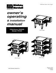
II. PRINCIPLE OF AIR FLOW<br />
The fan-style blower draws air into the oven plenum where<br />
it is heated. The blower then pushes the hot air through the<br />
air fingers into the baking chamber. Each air finger<br />
contains an inner plate and outer plate that form the hot air<br />
into jets, distributing it across a conveyor belt on which the<br />
food product rides. Air is then pulled back into the blower<br />
and the process continues. The curving, black arrows of<br />
Figure 1-4 show this air flow.<br />
A. Heat Transfer and How It Works<br />
1. Heat constantly moves from a warm object to a cold<br />
object. Heat moves using three different paths: Conduction;<br />
Radiation; and Convection.<br />
Conduction: This path utilizes surface-to-surface contact.<br />
The pizza dough in contact with the pan is a good<br />
example of conduction.<br />
Radiation: This path has to do with objects radiating heat.<br />
Dark objects absorb heat whereas light or shiny objects<br />
reflect more heat. This is the reason that the inside of a<br />
SECTION 1<br />
DESCRIPTION<br />
BE2136-Series Oven is light in color: To reflect more heat<br />
back onto the food product.<br />
Convection: This path has to do with moving a volume of<br />
air. It explains why hot air rises and cooler air replaces hot<br />
air. An industrial application of this principle is to incorporate<br />
a fan to force the hot air movement, which in turn<br />
increases the heat transfer to the food product.<br />
Each BE2136-Series Oven has a large fan-style blower to<br />
move the hot air through the air fingers and onto the<br />
product to cook/bake the food product most efficiently.<br />
2. Temperature is the intensity of heat at the point where<br />
it is sensed. As discussed above, heat flows by conduction,<br />
radiation and convection. The speed at which the heat<br />
flows is determined by the temperature difference between<br />
the oven and the food product. The larger the difference,<br />
the faster the heat flows to the item that is being baked.<br />
Upper Air Fingers<br />
Conveyor Belt(s)<br />
Window<br />
Lower Air Fingers<br />
Figure 1-4. PS536ES-Series Oven Air Flow<br />
3
SECTION 1<br />
DESCRIPTION<br />
II. PRINCIPLE OF AIR FLOW (Continued)<br />
B. Air Fingers<br />
The BE2136-Series Ovens are conveyorized ovens that<br />
employ vertical jets of hot air streaming from air fingers<br />
(Figure 1-5) to give uniform, intense heating. The vertical<br />
streams of hot air provide an exceptional heat transfer rate<br />
and generally bake faster and at lower temperatures than<br />
convection hot air or infrared heating ovens.<br />
A BE2136-Series Oven can accommodate up to four<br />
bottom air fingers and four top air fingers. Some BE2136-<br />
Series ovens used to bake pizza have four bottom fingers<br />
and two top fingers. For special product baking requirements,<br />
a number of other styles of fingers and finger<br />
arrangements are available from the factory.<br />
NOTE: Some customers have a predetermined finger<br />
arrangement. If you have any questions pertaining to the<br />
finger arrangement, please call the factory.<br />
Manifold<br />
Air Flow<br />
From Plenum<br />
Manifold Baffle<br />
Outer Plate<br />
Inner Plate<br />
High Velocity<br />
Columns of Air<br />
on Food Product<br />
Air Flow<br />
From Plenum<br />
Manifold Baffle<br />
Inner Plate<br />
Manifold<br />
Outer Plate<br />
Figure 1-5. Air Fingers, Showing High-Velocity Columns of Air Formed During Passage Through<br />
the Inner Plate and Outer Plate to Heat the Food Product.<br />
4
III. COMPONENT FUNCTION (Figure 1-6)<br />
SECTION 1<br />
DESCRIPTION<br />
Figure 1-6. BE2136-Series Oven Components Locations<br />
5
SECTION 1<br />
DESCRIPTION<br />
III. COMPONENT FUNCTION<br />
A. Conveyor Motor and Conveyor Belt<br />
The conveyor belt is driven by a variable-speed electric<br />
motor (Figure 1-7) operating through a gear reducer. The<br />
motor speed is controlled by a digital control. The stainless-steel<br />
wire belt can travel in either direction at variable<br />
rates ranging from 3 minutes to 30 minutes; this is the time<br />
that a product can take to pass through the oven.<br />
B. Blower Fan<br />
The blower fan is located at the rear of the oven. This<br />
blower forces heated air through the air fingers. The<br />
BLOWER/Heat switch must be set to “ON” or “I” for oven<br />
warmup and baking.<br />
C. Electric Heaters<br />
There is one heater element mounted on the inside of the<br />
left panel. The element is connected to an electrical<br />
control which is energized by the temperature controller.<br />
If the pilot flame does not light or a loss of flame occurs,<br />
the main gas valve closes.<br />
The main burner gas is extinguished when the HEAT<br />
switch is set to “OFF” or “O”.<br />
D. Window<br />
A window on the front of the oven permits viewing the items<br />
being baked and provides access to the oven for items that<br />
do not require full baking time, such as sandwiches,<br />
cookies, small items, or cheese-melting processes.<br />
E. Cooling Fan — See Figure 1-8<br />
The cooling fans are located in the back of the oven.<br />
These cooling fans draw air through its grille, blowing it<br />
through the blower motor compartment and the control<br />
compartment into the oven top and exhausted out the front<br />
louvers.<br />
F. Air Fingers and Blank Plates - See Figure 1-9<br />
F1. Air Fingers<br />
An Air Finger Assembly is made up of three parts:<br />
1.Outer Plate - The Outer Plate is the removable covering<br />
with tapered holes, which direct the air stream onto the<br />
product being baked.<br />
2. Inner Plate -The perforated Inner Plate is vital in forming<br />
the unique air jets. It must be assembled into the manifold<br />
with its holes aligned with the holes of the outer plate.<br />
3. Manifold - The Manifold is the assembly which slides<br />
on tracks into the oven plenum.<br />
Figure 1-7. Machinery Compartment<br />
Components<br />
6
SECTION 1<br />
DESCRIPTION<br />
Figure 1-8. Cooling Fan<br />
7
SECTION 1<br />
DESCRIPTION<br />
F2. Blank Plates<br />
1. Blank Plates- The Blank Plates are available to install<br />
on the plenum where an air finger is not required.<br />
Half Blank Plate<br />
Outer Plate<br />
Blank Plate<br />
Inner Plate<br />
Finger<br />
Manifold<br />
Assembly<br />
Baffle<br />
Figure 1-9. Blank Plates (two sizes) and an Air Finger.<br />
8
SECTION 2<br />
INSTALLATION<br />
SECTION 2<br />
INSTALLATION<br />
NOTE: The oven, when installed, must be electrically<br />
grounded in accordance with local codes, or in the absence<br />
of local codes, with the National Electrical Code<br />
(NEC), or ANSI/NFPA70.<br />
NOTE<br />
There must be adequate clearance between<br />
the oven and any adjacent combustible construction.<br />
Clearance must also be provided<br />
for servicing and for operation.<br />
CAUTION<br />
It is required that the oven be placed under a<br />
ventilation hood for adequate air supply and<br />
ventilation.<br />
CAUTION<br />
Do not obstruct the flow of combustion and<br />
ventilation air to and from your oven. Do not<br />
obstruct the ventilation holes in the Control Panel.<br />
CAUTION<br />
On ovens with the Machinery Drive Compartment<br />
located at the right end, a minimum clearance of<br />
0″ to a left side wall, 18″ to a right side wall and 6″<br />
from a back wall to air openings at the rear of the<br />
oven must be maintained. On ovens with the<br />
machinery/drive compartment located at the left<br />
end, a minimum clearance of 0″ to a right side<br />
wall, 18″ to a left side wall and 6″ from a back wall<br />
to air openings at the rear of the oven must be<br />
maintained.<br />
For servicing and cleaning, a minimum of 18″<br />
clearance from all walls is recommended.<br />
I. UNLOADING<br />
Your Blodgett BE2136-Series Oven is shipped partially<br />
assembled. It will arrive in a carton on a crate.<br />
Carton size for a BE2136-Series Oven is:<br />
58″ (2134mm) Long ×<br />
47.25″ (1473mm) Wide ×<br />
36″ (1118mm) High ×<br />
The crate and carton must be examined before signing the<br />
Bill of Lading. Report any visible damage to the transport<br />
company, and check for the proper number of crates. If<br />
apparent damage is found, make arrangements to file a<br />
claim against the carrier. Surface Interstate Commerce<br />
Regulations (U.S.A.) require that the claim must be<br />
initiated by the consignee within 10 days from the date that<br />
the shipment is received.<br />
A Pre-installation Procedures Manual (MM P/N 88910-0009)<br />
is attached to the exterior wall of the carton. This manual<br />
contains detailed instructions on unpacking and moving the<br />
oven(s) to the operating site. When the transport company<br />
notifies you of an impending delivery, arrange to have a forklift<br />
at your facility to unload the carton(s).<br />
Instructions for stacking the ovens is continued in a<br />
separate manual used by Blodgett Authorized Installers.<br />
If you have a door wider than the carton, simply move the<br />
carton into your facility and arrange an appointment with<br />
your Blodgett Authorized Installer.<br />
If your door is narrower than the carton, then the oven will<br />
have to be unpacked. Follow the directions shown in the<br />
Pre-Installation Procedures Manual.<br />
9
SECTION 2<br />
INSTALLATION<br />
BE2136 OVEN INSTALLATION<br />
REQUIRED KITS AND EQUIPMENT<br />
TYPE BE2136 BE2136 BE2136 BE2136<br />
OF Single Oven Double Oven Triple Oven Additional Cavity<br />
INSTALLATION Installation Installation Installation Installation<br />
Kit P/N Kit P/N Kit P/N Kit P/N<br />
44919 44920 44921 44974<br />
45529 (CE) 45530 (CE) 45531 (CE) 45532 (CE)<br />
BE2136 Single Oven 1 1<br />
BE2136 Double Oven 1 2<br />
BE2136 Triple Oven 1 3<br />
10
SECTION 2<br />
INSTALLATION<br />
Figure 2-1 - Installation Kit<br />
I. INSTALLATION KIT - see Figure 2-1<br />
Qty. Qty. Qty. Inc. with Inc. with<br />
Single Double Triple domestic CE<br />
Item Oven Oven Oven Part No. ovens? ovens? Description<br />
1 1 1 1 48605 Yes Yes Top panel<br />
2 4 4 4 3A80A8801 Yes Yes Screw, pan head #10 x 2″<br />
3 1 1 1 42893 Yes Yes Base pad<br />
4a 4 4 -- 42890 Yes Yes 17-1/2″ (445mm) leg extension, for single and<br />
double ovens<br />
4b -- 4 -- 45360 Yes Yes 20-1/2″ (521mm) leg extension, optional<br />
4c -- 4 -- 45329 Yes Yes 25-1/2″ (648mm) leg extension, optional<br />
4d -- -- 4 44799 Yes Yes 6″ (152mm) leg extension, for triple ovens<br />
5 2 2 2 22290-0009 Yes No Caster, with flat plate and brake<br />
6 A/R A/R A/R 22290-0010 Yes Yes Caster, with flat plate (no brake)<br />
NOTE: Domestic and standard export ovens include 2 braking casters (item 5) and 2 non-braking casters (Item 6). CE-approved<br />
ovens include 4 non-braking casters (Item 6) SOLELY for the purpose of moving the oven to the installation location. Casters are<br />
NOT suitable for use as part of CE oven installations. Refer to the notice on the preceding page.<br />
7 4 4 4 22450-0028 No Yes Leg, adjustable, 6″ (152mm)<br />
8 1 1 1 21392-0004 Yes No Eyebolt, 3/4″<br />
9 A/R A/R A/R 220373 Yes Yes Hex bolt, 3/8″-16 x 1″<br />
NOTE: CE-approved ovens include 32 hex bolts. Domestic and standard export ovens include 31 hex bolts and one eyebolt (item 8)<br />
that acts as an anchor for the restraint cable (Item 12). CE ovens are mounted on legs (Item 7) and do not use a restraint cable.<br />
10 32 32 32 21416-0001 Yes Yes Flat washer, 3/8″<br />
11 32 32 32 21422-0001 Yes Yes Lockwasher, 3/8″<br />
12 1 1 1 22450-0228 Yes No Restraint cable assembly<br />
13 1 2 3 22361-0001 Yes No Gas hose, 3/4″ to 1/2″ Gas hose reducer<br />
included with gas hose.<br />
14 1 1 1 50236 Yes Yes Owner's Operating and Installation Manual<br />
15 1 1 1 1002040 Yes Yes Authorized Service Agency Listing<br />
16 1 1 -- 46393 Yes Yes Lower shelf<br />
11
SECTION 2<br />
INSTALLATION<br />
Figure 2-5. MODEL BE2136 SINGLE OVEN DIMENSIONS<br />
2<br />
1<br />
ELECTRICAL JUNCTION BOX<br />
2<br />
2<br />
2<br />
RECOMMENDED MINIMUM CLEARANCES:<br />
Rear of Oven to Wall - 6″ (150mm)<br />
Non-control End of Oven to Wall - 0″<br />
Control End of Oven to Wall - 0″<br />
1<br />
12
SECTION 2<br />
INSTALLATION<br />
Figure 2-6. MODEL BE2136 DOUBLE OVEN DIMENSIONS<br />
2<br />
1<br />
ELECTRICAL JUNCTION BOX<br />
2<br />
2<br />
2<br />
RECOMMENDED MINIMUM CLEARANCES:<br />
Rear of Oven to Wall - 6″ (150mm)<br />
Non-control End of Oven to Wall - 0″<br />
Control End of Oven to Wall - 0″<br />
1<br />
13
SECTION 2<br />
INSTALLATION<br />
2<br />
1<br />
ELECTRICAL JUNCTION BOX<br />
2<br />
2<br />
2<br />
RECOMMENDED MINIMUM CLEARANCES:<br />
Rear of Oven to Wall - 6″ (150mm)<br />
Non-control End of Oven to Wall - 0″<br />
Control End of Oven to Wall - 0″<br />
1<br />
Figure 2-7. MODEL BE2136 TRIPLE OVEN DIMENSIONS<br />
RESTRAINT CABLE INSTALLATION<br />
Install the restraint cable assembly on the oven, as shown<br />
in Figure 2-6.<br />
Figure 2-8. Restraint Cable Assembly Installation<br />
14
UTILITY ROUGH-IN DIMENSIONS AND POSITIONING<br />
FOR BE2136-SERIES PS540-SERIES OVENS<br />
SECTION 2<br />
INSTALLATION<br />
WARNING<br />
DO NOT USE CONDUIT OR GAS LINE<br />
FOR GROUND CONNECTION.<br />
5<br />
6<br />
ON<br />
OFF<br />
2<br />
3<br />
CAUTION<br />
IT IS REQUIRED THAT THE OVEN BE<br />
PLACED UNDER A VENTILATION<br />
HOOD FOR ADEQUATE AIR SUPPLY<br />
AND VENTILATION.<br />
2<br />
2<br />
27"<br />
686mm<br />
3<br />
6<br />
1<br />
ON<br />
OFF<br />
24"<br />
610mm<br />
ELECTRIC AND GAS SUPPLY TO BE<br />
PROVIDED BY CUSTOMER<br />
2<br />
4<br />
13-1/2"<br />
343mm<br />
Suggested dimensions are shown; utility code<br />
requirements supersede any factors shown.<br />
24"<br />
610mm<br />
ELECTRICAL SAFETY SWITCH<br />
15 Amp circuit breaker / fused disconnect switch with<br />
lockout/tagout electrical shutoff for each oven. Wire<br />
each oven separately.<br />
ELECTRICAL SPECIFICATIONS<br />
DOMESTIC or EXPORT: 208-240V blower motor,<br />
1 phase, 4.1 Amp draw, 50/60 Hz, 208-240V control<br />
circuit, 2 poles, 3-wire system per oven (2 hot, 1 grd).<br />
Do NOT use conduit for ground.<br />
GAS RATING<br />
Model PS540 is 110,000 BTU/hour (27,720 kcal), 32.2 kW/hr.<br />
MINIMUM GAS METER RATING<br />
450 ft 3 /hour (12.6m 3 /h) for 1 or 2 ovens;<br />
Add 180 cu. ft./hr (5.1 m 3 /h) for each additional oven.<br />
Minimum rating does no take other gas appliances into<br />
consideration. Gas consumption varies at each site. Total<br />
BTU/hr (kcal/hr) must be calculated during high flame<br />
operation for each appliance to determine if the meter<br />
needs to be larger.<br />
MINIMUM GAS PIPE SIZE<br />
Natural: 2″ (51mm) ID for 1, 2, or 3 ovens with runs up<br />
to 200 ft. (61m).<br />
Must be a dedicated line.<br />
Runs over 200 ft, (61m) consult factory.<br />
Propane: 2″ (51mm) ID for 1, 2, or 3 ovens with runs up<br />
to 200 ft. (61m).<br />
Must be a dedicated line.<br />
Runs over 200 ft, (61m) consult factory.<br />
GAS SAFETY VALVE<br />
A 3/4″ (19mm) ID (inner diameter) full-flow, gas shutoff<br />
valve. A separate connection and valve must be provided<br />
for each oven, as shown in Figure 2-9.<br />
REQUIRED GAS SUPPLY PRESSURE<br />
Natural: 6″ to 12″ water column (13.8 to 29.9 mbar)<br />
Propane: 11.5″ to 12″ water column (28.7 to 29.9 mbar)<br />
SUGGESTED<br />
If space permits, electric and gas service should be<br />
located near the control console end of the oven(s) to allow<br />
convenient access to safety switches and valves.<br />
USER SUPPLIED ITEMS (Figure 2-9)<br />
ITEM<br />
Figure 2-9. Typical BE2136-Series Oven(s)<br />
Figure 2-9. Typical PS540-Series Oven(s)<br />
Installation<br />
Installation<br />
DESCRIPTION<br />
1 2″ (51mm) × 2″ (51mm) × 3/4″ (19mm) TEE<br />
2 3/4″ (19mm) × 3″ (76mm) NIPPLE<br />
3 3/4″ (19mm) FULL FLOW GAS SHUTOFF VALVE<br />
4 2″ (51mm) × 3/4″ (19mm) 90° REDUCER ELBOW<br />
5 2″ (51mm) ID GAS SUPPLY PIPE LINE - NATURAL GAS<br />
6 15 AMP TOGGLE SWITCH - 2 POLE for GAS<br />
15
SECTION 2<br />
INSTALLATION<br />
II. VENTILATION GUIDELINES<br />
A mechanically driven ventilation system is required for<br />
the BE2136 Series Blodgett conveyorized electric ovens.<br />
The minimum hood canopy dimensions are outlined below.<br />
Local codes and conditions vary greatly from one area to<br />
another and must be complied with. Following are the<br />
suggested requirements for good ventilation. Please remember<br />
these are recommendations or guidelines, you<br />
may have a special condition or problem that will require<br />
the services of a ventilation engineer or specialist. Proper<br />
ventilation is the oven owner’s responsibility. Improper<br />
ventilation can inhibit oven performance. It is recommended<br />
that the ventilation and duct work be checked out<br />
every three months. Grease filters in the intake of the hood<br />
may be required by local codes.<br />
VENTILATION HOOD<br />
The rate of air flow exhausted through the ventilation<br />
system is generally between 1400 and 2500 cu. ft./min.<br />
(40 and 70 m 3 /min), but may vary depending on the oven<br />
configuration and hood design. To avoid a negative<br />
pressure condition in the kitchen area, return air must be<br />
brought back to replenish the air that was exhausted. A<br />
negative pressure in the kitchen can cause heat related<br />
problems to the oven components as if there were no<br />
ventilation at all. The best method of supplying return air<br />
is through the heating, ventilation and air conditioning<br />
system. Through they system, the air can be temperature<br />
controlled for summer and winter. Return air can be<br />
brought in directly from outside the building, but detrimental<br />
affects can result from either extreme seasonal hot and<br />
cold temperature from the outdoors.<br />
NOTE: Return air from fan driven system within the hood<br />
must not blow at opening of bake chamber or poor oven<br />
baking performance will result.<br />
Figure 2-10. Vent Hood<br />
16
III. ELECTRICAL CONNECTION<br />
INFORMATION FOR BE2136-SERIES<br />
OVENS.<br />
WARNING<br />
Authorized supplier personnel normally accomplish<br />
the connections for the ventilation system,<br />
electric supply, and gas supply, as arranged by<br />
the customer. Following these connections, the<br />
factory-authorized installer can perform the initial<br />
startup of the oven.<br />
Check the oven data plate (Figure 2-11) before making any<br />
electric supply connections. Electric supply connections<br />
must agree with data on the oven data plate.<br />
NOTE: The electric supply installation must satisfy the<br />
requirements of the appropriate statutory authority, such<br />
as the National Electrical Code (NEC), ANSI/NFPA70,<br />
(U.S.A.); the Canadian Electrical Code, CSA C22.2; the<br />
Australian Code AG601; or other applicable regulations.<br />
A fused disconnect switch or a main circuit breaker<br />
(customer furnished) MUST be installed in the electric<br />
supply line for each oven; it is recommended that this<br />
switch/ circuit breaker have lockout/tagout capability. The<br />
electric supply connection must meet all national and local<br />
electrical code requirements. Copper is the recommended<br />
material for the electrical supply conductors.<br />
SECTION 2<br />
INSTALLATION<br />
IV. ELECTRIC SUPPLY FOR<br />
ELECTRICALLY HEATED OVENS<br />
Power requirements for electrically heated ovens are<br />
usually 208 - 240VAC, 3-phase, 4-wire (3 ‘hot’, 1 ground),<br />
although ovens built for export can have power requirements<br />
of 380VAC and 480VAC. (These ovens have a 5-<br />
wire system.) A 2″ (51mm) diameter cutout/hole in the<br />
back of the machinery compartment provides access for<br />
the electrical supply connections. Using flexible cable(s)<br />
for the electrical power supply conductors requires a 2″<br />
(51mm) strain-relief fitting (not furnished) to enable safe<br />
access to the terminal block from which oven power is<br />
distributed.<br />
The supply conductors must be of the size and material<br />
(copper) recommended to provide the current required;<br />
(refer to the data plate for the ampere specifications). The<br />
electric current rating for each conductor supplying a<br />
BE2136-Series Oven must comply to local and national<br />
codes.<br />
Typical specifications for each BE2136-Series Oven are<br />
208V or 240V, 3-phase, 4-wire, 60-ampere, 17kW; this<br />
oven requires 60-ampere service. A BE2136-Series Double<br />
Oven (Figure 1-2) installation would require two 60-ampere<br />
service connections, one for each oven; the 17kW power<br />
consumption also doubles for such an installation to<br />
34kW.<br />
The 208V or 240VAC electrically heated oven uses two<br />
legs of the supplied power to provide 208V or 240VAC<br />
power for the oven control circuitry.<br />
Figure 2-11. Typical Electric Oven Data Plate<br />
Figure 2-12. Junction Connection Box<br />
17
SECTION 2<br />
INSTALLATION<br />
VI. CONVEYOR REAR STOP AND END<br />
STOP INSTALLATION<br />
Locate the conveyor rear stop and end stop in the<br />
installation kit. Install the rear stop and end stop at the exit<br />
end of the oven. See Figure 2-13.<br />
Figure 2-13. Installing Rear and End Stops<br />
18
SECTION 3<br />
OPERATION<br />
SECTION 3<br />
OPERATION<br />
I. CONTROL FUNCTIONS<br />
Figure 3-1. BE2136-Series Oven Control Functions<br />
WARNING<br />
A possibility of injury from rotating parts and<br />
electric shock exists in this oven.<br />
Never disassemble or clean the oven with the<br />
BLOWER/HEAT switch or any other oven<br />
control turned “ON” or “I”. Turn “OFF” or “O” and<br />
lockout or tagout all electric power to the oven<br />
before attempting to clean or service this oven.<br />
19
SECTION 3<br />
OPERATION<br />
II. COMPONENT INFORMATION AND<br />
LOCATION (Figures 3-1 and 3-2)<br />
A. Door Safety Switch<br />
The Door Safety Switch is located at the lower left side of<br />
control panel opening. Opening the control panel door<br />
permits this switch to open, disconnecting power to all<br />
electrical controls.<br />
CAUTION<br />
Do NOT touch the wires going to this safety<br />
switch. Current is always present.<br />
B. Blower Switch<br />
The blower switch has two positions. The switch must be<br />
“ON” or “I” for the burner to come on and permit the oven<br />
to warm up. The fan circulates the air throughout the oven<br />
and must stay on during baking and during the cool down<br />
cycle above 200°F (93°C) to prevent blower bearing<br />
damage. To protect the blower motor and bearings a<br />
thermostatic override is built into the oven. If the temperature<br />
inside the oven is over 180°F (82°C) the main<br />
blower will continue to run after the blower switch is<br />
turned to the “OFF” or “O” position.<br />
An air pressure switch monitors the air flow from the<br />
blower, acting as a safety interlock for the burner. The<br />
burner cannot light, if the air switch does not sense air<br />
flow off the main blower fan.<br />
C. Heat Switch<br />
Turning the HEAT switch to “ON” or“I” will initially set<br />
up the oven purge circuit. After approximately 30<br />
seconds, the burner lights. After the burner is lit, a<br />
flame sensor sends a signal to the ignition module to<br />
stop the spark. The burner will run unless the flame<br />
sensor does not detect a flame or the heat switch is<br />
turned to the “OFF” or “O” position.<br />
The HEAT switch is in series with the burner blower<br />
motor centrifugal switch, the high-temperature safety<br />
switch, and the blower fan air pressure switch. All three<br />
safety switches must be closed for gas to flow and the<br />
burner to light.<br />
D. Temperature Controller<br />
The temperature controller is a solid-state, on/off type to<br />
maintain the operator-set temperature. The temperature<br />
controller continuously monitors the oven temperature<br />
and turns on the modulating solenoid valve in a gasheated<br />
oven. The heat is on for the time required to<br />
maintain a constant oven temperature.<br />
The temperature controller contains a low-limit switch<br />
which allows the oven to cool down to 200°F (93°C) before<br />
shutting off the blower. A high-limit indication (ALM 1) will<br />
appear on the display if the oven reaches 650°F (343°C).<br />
Figure 3-2. Interior View of Machinery Compartment and Control Console<br />
20
SECTION 3<br />
OPERATION<br />
E. Conveyor<br />
The on-off switch for the conveyor motor is on the control<br />
panel. Also on the control panel is the digital conveyor<br />
speed control. The digital control can be adjusted from 3<br />
min. to 30 min. bake time (conveyor speed). Refer to<br />
Figure 3-3.<br />
Conveyor speed is measured by the amount of time it<br />
takes for an item to go through the bake chamber of the<br />
oven.<br />
MEASURING CONVEYOR SPEED.<br />
See Figures 3-4 and 3-5.<br />
To check conveyor speed, place a product item at the<br />
entrance end of baking chamber as shown. Time how<br />
long it takes for the leading edge of the item to go from the<br />
entrance end of the baking chamber to the exit end. This<br />
should be the conveyor speed shown on the conveyor<br />
speed digital control.<br />
NOTE: In Figures 3-4 and 3-5, the oven shown is with the<br />
conveyor running right to left.<br />
WARNING<br />
Possibility of injury from rotating parts and<br />
electrical shock exist in this oven.<br />
Never disassemble or clean the oven with the<br />
BLOWER/HEAT switch or any other part of<br />
the oven turned “ON” or “I”. Turn “OFF” or “O”<br />
and lockout or tagout all electrical power to the<br />
oven before attempting to clean or service<br />
this oven.<br />
Figure 3-3. Conveyor Speed Digital Control<br />
Figure 3-4. Product at entrance end of baking<br />
chamber – BEGINNING OF TIMING<br />
21<br />
Figure 3-5. Product at exit end of baking<br />
chamber – END OF TIMING
SECTION 3<br />
OPERATION<br />
WARNING<br />
OVEN MUST BE KEPT CLEAR OF<br />
COMBUSTIBLES AT ALL TIMES.<br />
III. STEP-BY-STEP OPERATION<br />
Control Panel (On split belt ovens, two conveyor speed<br />
controls are mounted on the control panel.)<br />
A. Startup Procedures<br />
Daily Startup<br />
1. Turn the BLOWER/HEAT switch (Figure 3-6) to the<br />
“ON” or “I” position. This starts the main blower fan and the<br />
cooling fan. The blower circulates air through the air fingers<br />
and must stay on during the cooking or baking process.<br />
2. Check to see if the cooling fan (see Figure 1-8) is operating<br />
when the BLOWER/HEATswitch (see Figure 3-6) is turned<br />
“ON” or “I”. The cooling fans cool the control components and<br />
burner blower motor. The cooling fan, located at the rear of the<br />
electrical control cabinet blows air into and through the cabinet.<br />
Air is exhausted through the front of the cabinet and also out<br />
the front of the oven. Refer to Daily Maintenance Section for fan<br />
intake checking procedure.<br />
IMPORTANT NOTE<br />
The cooling fan operates when the BLOWER/<br />
HEAT switch is turned “ON” or “I”. It must operate<br />
to keep the control console below 140°F (60°C).<br />
4. Set the temperature controller to the desired baking<br />
temperature. See section on bake times to determine<br />
desired temperature.<br />
NOTE: For complete temperature controller operation<br />
instructions refer to Step C.<br />
5. Turn the HEAT switch (Figure 3-6) to the “ON” or “I”<br />
position. This completes a circuit to supply electric power<br />
to the electric heating system.<br />
6. Close front window.<br />
7. Oven will reach a baking temperature of 500°F (232°C)<br />
in approximately 10 minutes. Allow the oven to cycle for<br />
30 minutes after it has reached desired bake temperatue.<br />
The oven is now ready for baking.<br />
Power Failure<br />
In case of power failure, turn off all switches; open oven<br />
window and remove product. After power has been<br />
reestablished follow normal startup procedure.<br />
B. Shutdown Procedure<br />
1. Turn the BLOWER/HEAT switch to “OFF” or “O”.<br />
NOTE: The blowers will remain on until the oven temperature<br />
cools down to 200°F (93°C) at which time they<br />
will stop automatically.<br />
2. Make certain that there are no products left on the<br />
conveyor inside the oven. Turn the CONVEYOR switch<br />
to “OFF” or “O”.<br />
3. Open the oven window.<br />
3. Turn the CONVEYOR switch (Figure 3-6) to the “ON” or<br />
“I” position. This starts the conveyor belt moving through<br />
the oven. Set the conveyor speed for the desired baking<br />
time. Refer to the following Procedures E, F and G.<br />
22
SECTION 3<br />
OPERATION<br />
D<br />
C<br />
B<br />
A<br />
LOCATION AND DESCRIPTION OF CONTROLS<br />
Figure 3-6. Control Panel<br />
A.<br />
B.<br />
C.<br />
"BLOWER/HEAT" Switch: Turns the blower<br />
and cooling fans on and off, as well as, the gas<br />
burner system. The gas burners will activate<br />
shortly after the BLOWER/HEAT switch is turned<br />
on. The Temperature of the oven will be regulated<br />
by the temperature controller.<br />
"CONVEYOR" Switch: Turns the conveyor<br />
drive motor on and off.<br />
Conveyor Speed Controller: Adjusts and displays<br />
the bake time. Single-belt ovens have one<br />
controller. Split belt ovens have one controller<br />
for each conveyor belt, labeled "FRONT" and<br />
"BACK."<br />
23<br />
D. Digital Temperature Controller: Continuously<br />
monitors the oven temperature. Settings on the<br />
Digital Temperture Controller control the activation<br />
of the burner. Keypad controls allow the<br />
operator to select the cooking temperature and<br />
monitor oven operation.<br />
NOT SHOWN:<br />
E. Machinery and Control Compartment Safety Switches:<br />
Disconnect electrical power to the controls and blowers<br />
when EITHER the machinery compartment door OR the<br />
control compartment door is opened. The doors should only<br />
be opened by authorized service personnel.
SECTION 3<br />
OPERATION<br />
II.<br />
NORMAL OPERATION - STEP-BY-STEP<br />
A. DAILY STARTUP PROCEDURE<br />
1. Check that the circuit breaker/fused disconnect is in the on<br />
position. Check that the window is closed.<br />
2. Turn the "BLOWER/<br />
HEAT" ( )( )switch<br />
to the “ON” ("I") position.<br />
3. Turn the "CONVEYOR"<br />
( ) switch to the “ON”<br />
("I") position.<br />
8. Allow the oven to preheat for 10 minutes after it has reached<br />
the set point temperature.<br />
B. DAILY SHUTDOWN PROCEDURE<br />
1. Turn the "BLOWER"/<br />
"HEAT" ( )( ) switch<br />
to the "OFF" ("O") position.<br />
Note that the blowers<br />
will remain in operation<br />
until the oven has<br />
cooled to below 200°F<br />
(93°C).<br />
4. If necessary, adjust the<br />
conveyor speed setting<br />
by pressing the or<br />
pushbuttons on the conveyor<br />
speed controller to<br />
change the displayed<br />
bake time.<br />
or<br />
2. Make certain that there<br />
are no products left on<br />
the conveyor inside the<br />
oven. Turn the "CON-<br />
VEYOR" ( ) switch to<br />
the "OFF" ("O") position.<br />
3. Open the window to allow the oven to cool faster.<br />
5. Adjust the temperature<br />
controller to a desired set<br />
temperature, if necessary.<br />
• Press the Set Point<br />
and Unlock keys at<br />
the same time. Wait<br />
for the "SET PT" light<br />
to turn on.<br />
+<br />
wait<br />
for<br />
4. After the oven has cooled and the blowers have turned off,<br />
switch the circuit breaker/fused disconnect to the off position.<br />
• Press the Up Arrow<br />
and Down Arrow<br />
Keys as necessary<br />
to adjust the setpoint.<br />
6. Wait for the oven to heat to the setpoint temperature. Higher<br />
setpoint temperatures will require a longer wait. The oven<br />
can reach a temperature of 500°F (232°C) in approximately<br />
15 minutes.<br />
7. (Optional) Press the Temperature<br />
( ) key to show<br />
the Actual Temperature<br />
in the display, and wait<br />
for the "ACTUAL TEMP"<br />
light to turn on. This allows<br />
you to monitor the<br />
oven temperature as it<br />
rises to the setpoint.<br />
or<br />
wait<br />
for<br />
IMPORTANT<br />
On gas ovens, if the "HEAT ON" light will not illuminate, OR<br />
if the oven does not heat, the gas burner may not have lit.<br />
Turn the "BLOWER/HEAT" ( )( ), and "CONVEYOR"<br />
( ) switches to the "OFF" ("O") position. Wait for AT<br />
LEAST FIVE MINUTES before restarting the oven. Then,<br />
repeat the Daily Startup procedure.<br />
CAUTION<br />
In case of power failure, turn all switches to the “OFF” ("O")<br />
position, open the oven window, and remove the product.<br />
After the power has been restored, perform the normal<br />
startup procedure. IF THE OVEN WAS SWITCHED OFF<br />
FOR LESS THAN 5 MINUTES, WAIT FOR AT LEAST FIVE<br />
MINUTES BEFORE RESTARTING THE OVEN.<br />
The burner will not operate and gas will not flow through<br />
the burner without electric power. No attempt should<br />
be made to operate the oven during a power failure.<br />
24
SECTION 3<br />
OPERATION<br />
"SP LOCK"<br />
Light<br />
Lights when the set<br />
point is locked out<br />
from changes. This<br />
setting can only be<br />
changed by service<br />
personnel.<br />
Display<br />
Shows the Set Point<br />
or the Actual Temperature<br />
in degrees<br />
Fahrenheit (F) or<br />
Celsius (C).<br />
"HEAT ON" Light<br />
Lights when the<br />
burner is in<br />
operation.<br />
"SET PT"<br />
(setpoint) Light<br />
Lights when the set<br />
point is shown in<br />
the display.<br />
OVERTEMP<br />
Light<br />
Lights when the oven<br />
temperature is greater<br />
than 650°F (343°C).<br />
Refer to Quick<br />
Reference: Troubleshooting<br />
in this<br />
section.<br />
"ACTUAL TEMP"<br />
Light<br />
Lights when the Actual<br />
Temperature is shown<br />
in the display.<br />
Temperature Key<br />
Press this key once to<br />
view the Actual<br />
Temperature in the<br />
Display.<br />
Service Key<br />
Service use<br />
only.<br />
Unlock Key<br />
Press this key<br />
together with the Set<br />
Point Key to allow the<br />
Set Point to be<br />
changed. Changes<br />
can only be made for<br />
60 seconds.<br />
Up Arrow and Down<br />
Arrow Keys<br />
Press these keys to adjust<br />
the Set Point up or down.<br />
If the Set Point will not<br />
change, refer to Set Point<br />
Key and Unlock Key in<br />
this section.<br />
Set Point Key<br />
Press this key<br />
together with the<br />
Unlock Key to allow<br />
the Set Point to be<br />
changed.<br />
Changes can only be<br />
made for 60 seconds.<br />
25
SECTION 3<br />
OPERATION<br />
IV. QUICK REFERENCE: TROUBLESHOOTING<br />
SYMPTOM PROBLEM SOLUTION<br />
light is lit, food product is<br />
undercooked<br />
Oven will not<br />
turn on at all<br />
The oven temperature exceeded<br />
650°F (343°C), and<br />
the burner was automatically<br />
shut down.<br />
Electrical power may not be<br />
reaching the oven, or the<br />
controls may be set incorrectly.<br />
• Follow the procedures under Daily Shutdown Procedures in this<br />
section to shut down the oven. Contact your Middleby Marshall<br />
Authorized Service Agent to determine and correct the cause of<br />
the condition to prevent damage to the oven.<br />
• Check that the circuit breaker/fused disconnect is turned on.<br />
• Check that the "BLOWER" ( ) Switch is in the “ON” ("I")<br />
position. The burner cannot engage until the blowers are in<br />
operation.<br />
Oven shuts down shortly<br />
after it is turned on<br />
The gas burner did not light<br />
within 90 seconds of turning<br />
the "HEAT" ( ) Switch<br />
to the “ON” ("I") position.<br />
This automatically engages<br />
a safety lockout mode.<br />
• Turn the "HEAT" ( ), "BLOWER" ( ), and "CONVEYOR"<br />
( )switches to the "OFF" ("O") position.<br />
• Wait for AT LEAST FIVE MINUTES before restarting the oven.<br />
• Repeat the Daily Startup procedure.<br />
appears in display,<br />
oven is not heating<br />
The oven did not reach<br />
200°F (93°C) within 15 minutes<br />
of startup, and the oven<br />
has stopped heating.<br />
• Turn the "HEAT" ( ), "BLOWER" ( ), and "CONVEYOR"<br />
( )switches to the "OFF" ("O") position.<br />
• Wait for AT LEAST FIVE MINUTES before restarting the oven.<br />
• Repeat the Daily Startup procedure.<br />
Oven will not heat<br />
Controls may be set incorrectly.<br />
• Check that the Set Point is correctly set.<br />
• Check that both the "BLOWER" ( ) and "HEAT" ( ) Switches<br />
are in the “ON” ("I") position.<br />
• If the oven still will not heat,turn the "HEAT" ( ), "BLOWER"<br />
( ), and "CONVEYOR" ( )switches to the "OFF" ("O")<br />
position.<br />
• Wait for AT LEAST FIVE MINUTES before restarting the oven.<br />
• Repeat the Daily Startup procedure. Check that the Set Point<br />
is above 200°F (93°C).<br />
Oven is operating, but<br />
little or no air is blowing<br />
from air fingers<br />
Air fingers may have been<br />
reassembled incorrectly after<br />
cleaning.<br />
• Turn the oven to the “OFF” or “O” position, and allow it to cool.<br />
Disconnect electrical power to the oven.<br />
• Refer to Section 4, Maintenance, for instructions on reassembling<br />
the air fingers.<br />
Conveyor moves with a<br />
jerky motion, or will not<br />
move at all<br />
Conveyor may be jammed<br />
on an object in the oven, or<br />
conveyor belt or drive chain<br />
tension may be incorrect.<br />
• Turn the oven to the “OFF” or “O” position, and allow it to cool.<br />
Disconnect electrical power to the oven.<br />
• Check if the conveyor is blocked by an object inside the oven.<br />
• Refer to Section 4, Maintenance, for instructions on checking<br />
the conveyor and drive chain tension.<br />
Food products are<br />
overcooked or<br />
undercooked.<br />
Controls may be set incorrectly.<br />
• Check that the set temperature and bake time settings are<br />
correct.<br />
IF THESE STEPS FAIL TO RESOLVE THE PROBLEM, CONTACT YOUR LOCAL BLODGETT<br />
AUTHORIZED SERVICE AGENT. A SERVICE AGENCY DIRECTORY IS SUPPLIED WITH YOUR OVEN.<br />
26
SECTION 4<br />
MAINTENANCE<br />
SECTION 4<br />
MAINTENANCE<br />
WARNING<br />
Possibility of injury from rotating parts and electrical<br />
shock exist in this oven. Turn off and lockout or tagout<br />
electrical supply to oven(s) before attempting to<br />
disassemble, clean or service oven(s). Never disassemble<br />
or clean the oven with the blower switch or any<br />
other part of the oven turned on.<br />
WARNING<br />
Before performing any maintenance work or cleaning,<br />
turn main power switch off.<br />
CAUTION<br />
When cleaning do not use any abrasive cleaning<br />
materials or water spray, wipe clean only. Never use a<br />
water hose or pressurized steam cleaning equipment<br />
when cleaning this oven.<br />
NOTICE<br />
If the oven is to be removed from its installed location<br />
for servicing, perform the following procedure:<br />
1. Switch off the oven and allow it to cool. Do NOT<br />
service the oven while it is warm.<br />
2. Turn off main circuit breakers and disconnect<br />
connector from oven.<br />
3. Turn the adjustable legs to put weight on the<br />
casters.<br />
4. Move oven to desired location for servicing.<br />
5. When servicing is complete, move oven to original<br />
location.<br />
6. Adjust legs to level oven and take weight off<br />
casters.<br />
7. Connect electrical and gas connectors to oven.<br />
8. Turn on main circuit breakers.<br />
9. Follow normal startup instructions.<br />
27
SECTION 4<br />
MAINTENANCE<br />
I. MAINTENANCE - DAILY<br />
A. Exterior<br />
Everyday you should clean the outside of the oven with a<br />
soft cloth and mild detergent.<br />
WARNING<br />
Never use a water hose or pressurized steam<br />
cleaning equipment when cleaning the oven.<br />
D. Crumb Pans (Figure 4-2)<br />
Remove and clean the crumb pan at each end of the oven.<br />
Each crumb pan can be removed by sliding it out, as<br />
shown in Figure 4-2. Reinstall the crumb pans after<br />
cleaning.<br />
E. Window<br />
The window can be cleaned daily while it is in place.<br />
B. Cooling Fan<br />
1. TWO COOLING FAN GRILLES AT THE REAR OF<br />
EACH OVEN CONTROL COMPARTMENT MUST BE<br />
CLEANED DAILY - Clean grilles with a stiff nylon type<br />
brush.<br />
2. Check the air intake of the cooling fan daily. The best<br />
time to check is right after starting the oven.<br />
IMPORTANT NOTE<br />
The cooling fan operates when the blower switch<br />
is turned to “ON” (“I”). It must operate to keep the<br />
electrical control cabinet below 140°F (60°C).<br />
WARNING<br />
IF FAN BLADE IS NOT ROTATING, BROKEN,<br />
OR FAN ASSEMBLY IS MISSING FROM MAIN<br />
BLOWER MOTOR SHAFT, DO NOT OPERATE<br />
OVEN. REPLACE COOLING FAN BLADE<br />
BEFORE OPERATING OVEN. Serious damage<br />
could be done to the burner blower motor and/or<br />
solid-state electrical components if oven is<br />
operated while cooling fan is not running or vent<br />
grille is plugged.<br />
Figure 4-1. Oven Cooling Fans<br />
3. Using a stiff nylon brush clean control compartment<br />
vent grille. Hot air from control compartment exits from this<br />
grille.<br />
C. Conveyor Belt (Figure 4-2)<br />
Everyday, just after starting the oven, stand at the<br />
unloading end of the conveyor, and with a brush, remove<br />
food particles (crumbs, etc.) clinging to the conveyor belt,<br />
brushing them into the crumb pan.<br />
Figure 4-2. Conveyor Belt and<br />
Crumb Pan Cleaning<br />
28
II. MAINTENANCE - MONTHLY<br />
NOTE: The oven interior may require cleaning more<br />
than once a month depending on the volume of<br />
baking. To clean the interior, you have to disassemble<br />
some parts of the oven.<br />
When cleaning your Series BE2136 Oven note the<br />
following:<br />
PRECAUTIONS-<br />
1. Do not use excessive water or saturation of oven<br />
insulation will occur.<br />
2. Do not use a caustic oven cleaner or the aluminized<br />
finger manifold surfaces will be severely damaged.<br />
When cleaning your oven, first remove all heavy debris<br />
with a vacuum cleaner. Use a damp cloth for light cleaning.<br />
For heavier cleaning of baked on grease and carbon<br />
SECTION 4<br />
MAINTENANCE<br />
deposits use a non-caustic cleaner that will not react with<br />
the aluminized finger manifold surfaces.<br />
You can order non-caustic cleaner from your local authorized<br />
Blodgett Parts Distributor in the quantities listed<br />
below:<br />
Part #<br />
Quantity<br />
27170-0244 Case of Quarts (6)<br />
27170-0246 Case of Gallons (4)<br />
A. Removing Conveyor From Oven For Cleaning<br />
1. Remove crumb pans as shown in Figure 4-2.<br />
2. Remove upper and lower end plugs from each end of<br />
oven by removing the two wing screws from each end plug.<br />
3. Remove the conveyor end stop and the conveyor rear<br />
stop (Figure 4-3).<br />
Figure 4-3.<br />
29
SECTION 4<br />
MAINTENANCE<br />
4. Remove conveyor drive chain cover as shown.<br />
5. Remove tension from drive chain by lifting and pushing<br />
the conveyor slightly into the oven. Remove drive chain<br />
from conveyor drive sprocket as shown.<br />
NOTE: The split belt conveyor assembly can only be<br />
removed from the drive end of the oven.<br />
6. Begin sliding conveyor out of the oven as shown.<br />
Figure 4-4.<br />
Figure 4-7.<br />
7. Continue sliding the conveyor completely out of the<br />
oven, fold it in half and then place it to the side for cleaning.<br />
Be careful not to bump drive sprocket while handling<br />
conveyor or damage may result to drive shaft.<br />
Figure 4-5.<br />
Figure 4-8.<br />
CAUTION<br />
Be careful not to bump the drive sprocket while<br />
handling the conveyor, to avoid damaging the<br />
drive shaft.<br />
Figure 4-6.<br />
30
B. Air Fingers Disassembly For Cleaning<br />
1. As the air fingers are removed use a felt pen to mark all<br />
parts of the fingers. This includes the finger manifold, inner<br />
plate and the outer plate (refer to Figure 1-9). If a blank or<br />
choke plate is used, mark that plate also. Fingers are<br />
marked in the order shown; as viewed from the front of the<br />
oven. (The marks for an upper oven should be preceded<br />
with a “U”, example UB1, UT2, etc.)<br />
SECTION 4<br />
MAINTENANCE<br />
T1 T2 T3 T4<br />
B1 B2 B3 B4<br />
Standard Fingers<br />
2. Slide blank plates straight out.<br />
Figure 4-10.<br />
4. With air fingers out, place them in an upright position to<br />
remove the outer plate.<br />
5. Gently step o the lip of the finger and pull the outer plate<br />
off.<br />
Figure 4-9.<br />
3. Remove air fingers.<br />
NOTE: Some oven users require a custom finger arrangement<br />
where the quantity of air fingers may vary.<br />
You can remove top and bottom fingers and blank plates<br />
from each or either end. It is highly recommended that<br />
each finger be marked before removing so it is placed in<br />
exactly the same position when reassembled<br />
(refer to step 1).<br />
Remove the air fingers, pull the finger at the back side - pull<br />
straight out.<br />
Figure 4-11.<br />
31
SECTION 4<br />
MAINTENANCE<br />
6. To remove the inner plate, pull the plate out and then up.<br />
D. Reassembly of Air Fingers<br />
1. Air fingers are made up of one inner plate, one outer<br />
plate and the finger housing manifold. Be sure to match up<br />
the markings (T1, T2, T3, etc.) on all the parts of the air<br />
fingers as you are reassembling.<br />
Figure 4-12.<br />
7. The outer finger plate is stainless and may be cleaned<br />
by either soaking in a hot, strong detergent solution or<br />
using a caustic cleaner. The conveyor belt can also be<br />
cleaned in the same way.<br />
Figure 4-15.<br />
2. Reassemble the inner plate. Keep your fingers clear so<br />
you won’t pinch them. The inner plate of a finger will only<br />
go in one way because of its design.<br />
3. Replace the outer plate by placing your hands flat on<br />
the top of the plate and pushing down. Keep your fingers<br />
clear so you won’t pinch them.<br />
Figure 4-13. Standard Lower Finger<br />
Figure 4-16.<br />
Figure 4-14. Standard Upper Finger<br />
C. Cleaning the Window<br />
The window can be cleaned in place.<br />
32
4. Replace the air fingers by pushing in at the back side.<br />
Remember to replace them according to the numbers<br />
marked on them when they were removed. They must go<br />
back in the same way they came out.<br />
SECTION 4<br />
MAINTENANCE<br />
IMPORTANT: When inserting fingers the tab on<br />
the outer plate must be in the groove as shown in<br />
Figure 4-18. There is a blocking tab on the outside<br />
of the groove which will prevent inserting the<br />
finger in the groove if the outer plate is moved<br />
away from the flange of the finger manifold.<br />
Figure 4-17.<br />
Extended Lip<br />
Tab on<br />
Outer Plate<br />
Flange of<br />
Finger Manifold<br />
Tab on<br />
Outer Plate<br />
Figure 4-18.<br />
33
SECTION 4<br />
MAINTENANCE<br />
5. Install fingers and blank plates correctly with edges<br />
interlocked and no space between edges.<br />
Top Finger<br />
Incorrect - Too<br />
Much Space<br />
Blank Plate<br />
Tab on Outer Plate of Finger<br />
Located in Groove<br />
Top Finger<br />
Incorrect - Too<br />
Much Space<br />
Blank Plate<br />
Tab on Outer Plate of Finger<br />
Located in Groove<br />
Top Finger<br />
Correct -<br />
Edges Overlap<br />
Completely<br />
Blank Plate<br />
Tab on Outer Plate of Finger<br />
Located in Groove<br />
Figure 4-19.<br />
34
E. Reinstall End Plugs<br />
1. Reinstall lower end plug. Be sure to tighten two wing<br />
screws on the end plug.<br />
2. Reinstall conveyor.<br />
3. Reinstall upper end plug. Be sure to tighten two wing<br />
screws on the end plug.<br />
SECTION 4<br />
MAINTENANCE<br />
Figure 4-20.<br />
Figure 4-21.<br />
35
SECTION 4<br />
MAINTENANCE<br />
F. Conveyor Reassembly Into Oven<br />
1. Lift conveyor and position it in oven as shown.<br />
NOTE: Conveyor assembly may be inserted into either<br />
end of oven. If it is to be installed from the non-drive end<br />
of the oven the drive sprocket assembly must be removed<br />
as shown in conveyor disassembly section.<br />
NOTE: Split belt conveyors can only be inserted from the<br />
drive end of the oven.<br />
G. Checking Conveyor Belt Tension<br />
WARNING<br />
Oven conveyor belt must be cool when adjusting<br />
belt. Do not adjust belt if HOT.<br />
1. With the conveyor assembly in the oven, stand at one<br />
end of conveyor and check tension by lifting the conveyor<br />
belt at the center of the oven chamber opening. The belt<br />
should not lift higher that 3″ to 4″ (75mm to 102mm).<br />
2. Adjust conveyor belt tension screws (located on left<br />
end of oven) for the 3″ to 4″ (75mm to 102mm) deflection<br />
as shown in Figure 4-26. If there is proper tension, proceed<br />
to “J. Attaching Drive Chain”. If belt is still too loose,<br />
continue to step 3 below.<br />
3. If conveyor belt is still not under proper tension, an<br />
entire link must be removed. Use the following procedure<br />
“H. Conveyor Belt Link Removal” to remove a link. If<br />
conveyor belt is under proper tension proceed directly to<br />
“J. Attaching Drive Chain”.<br />
Figure 4-22.<br />
2. Reinstall the conveyor rear stop. Reinstall the conveyor<br />
end stop.<br />
Conveyor Rear Stop<br />
Conveyor End Stop<br />
Figure 4-24.<br />
Figure 4-23.<br />
36
H. Conveyor Belt Link Removal<br />
1. Using long nose pliers, an entire link can be removed<br />
with the conveyor assembly either in or out of the oven.<br />
Position master links at end of conveyor as shown in<br />
Figure 4-25.<br />
SECTION 4<br />
MAINTENANCE<br />
4. Unhook the link to be removed.<br />
5. Pull up on the belt link section and remove. Do not<br />
discard the link removed as it may be used for making<br />
spare master links.<br />
NOTE: If a section of the conveyor belt is being replaced<br />
it should be done now. Remove the links that need<br />
replacing and use the section of conveyor belt furnished in<br />
your installation kit to replace them.<br />
Master<br />
Links<br />
Figure 4-25.<br />
2. Using long nose pliers, unhook master links at left end<br />
of conveyor as shown in Figure 4-26.<br />
Figure 4-28.<br />
NOTE: Before connecting the inside master links, notice<br />
that these links have a correct position (Figure 4-29). The<br />
link at the right is in the correct (horns up) position for<br />
inserting into the conveyor belt. The horns facing down are<br />
in the incorrect position.<br />
Correct<br />
Position<br />
Figure 4-26.<br />
3. Remove the outside master links on the right and left<br />
sides of the conveyor belt as shown in Figure 4-27.<br />
Incorrect<br />
Position<br />
Figure 4-29.<br />
Figure 4-27.<br />
37
SECTION 4<br />
MAINTENANCE<br />
6. Reconnect the inside master links (Figure 4-30.)<br />
Figure 4-30.<br />
NOTE: The outside master links have right and left sides<br />
to them. The right edge master link has an open hook<br />
facing you as shown in Figure 4-31. This will match up with<br />
the outer edges of the conveyor belt. Remember this hook<br />
travels backwards on the conveyor.<br />
I. Replacing Conveyor Belt<br />
If a section of the conveyor belt needs replacing it can be<br />
done with the conveyor assembly either in or out of the<br />
oven. The section of the conveyor belt furnished with the<br />
oven in the installation kit may then be used to replace a<br />
section. Follow the preceding procedure “H. Conveyor belt<br />
link removal” which outlines the disassembly procedure.<br />
J. Attaching Drive Chain<br />
1. If drive sprocket assembly was removed reassemble it<br />
into the conveyor drive shaft. Be sure flat on end of drive<br />
shaft aligns with set screw in conveyor shaft collar. Once<br />
in place tighten 3/32″ set screw.<br />
2. Lift conveyor and install drive chain to conveyor drive<br />
sprocket and motor sprocket.<br />
Direction of travel<br />
Figure 4-31.<br />
7. Reconnect the outside master links.<br />
8. Replace all parts removed from the oven.<br />
Figure 4-33.<br />
3. The angle plate located on the underside of the conveyor<br />
must be against the lower end plug. This is true on<br />
both sides of oven.<br />
Crumb Pan<br />
Mounting<br />
Bracket<br />
Figure 4-32.<br />
Lower End Plug<br />
Figure 4-34.<br />
38
4. Reassemble conveyor drive chain cover and then<br />
reassemble the bottom cover to the drive chain cover.<br />
Install both upper end plugs.<br />
SECTION 4<br />
MAINTENANCE<br />
III. MAINTENANCE - EVERY 3 MONTHS<br />
WARNING<br />
Shut OFF all electrical power and lock/tag out the<br />
switch before attempting maintenance work.<br />
Shut OFF gas supply to oven.<br />
NOTE: It is recommended that the 3-month maintenance<br />
be performed by an authorized Middleby Marshall<br />
technician.<br />
A. Cleaning the Blower/Fan Motor<br />
To gain access to the blower/fan motor, open the control<br />
cabinet door by removing the three screws. Clean the<br />
motor, burner blower motor, the conveyor drive motor and<br />
the surrounding area, using either compressed air or CO 2<br />
.<br />
Thoroughly blow out the motor compartment and vents<br />
inside the motor (Figure 4-38). Failure to do this can cause<br />
premature failure of blower fan motor.<br />
Figure 4-35.<br />
CAUTION<br />
Not cleaning the blower/fan motor properly can<br />
cause premature failure.<br />
Figure 4-36.<br />
39
SECTION 4<br />
MAINTENANCE<br />
B. Electrical Terminals<br />
Open the control cabinet door by removing the three<br />
screws from the control cabinet door. Tighten all electrical<br />
control terminal screws including the electrical contactor<br />
terminal screws as shown in Figure 4-37.<br />
C. Ventilation<br />
Check that the air circulation throughout the oven is not<br />
blocked and is working properly.<br />
Figure 4-37.<br />
Figure 4-38.<br />
40
D. Split-belt Conveyor Shaft Cleaning<br />
It is very important that the split-belt conveyor drive and<br />
idler shafts are removed from the conveyor frame for<br />
cleaning and lubrication.<br />
SECTION 4<br />
MAINTENANCE<br />
4. Drop the idler shaft assembly clear of the frame through<br />
the front frame slot.<br />
CAUTION<br />
Use a turbine oil or light machine oil. DO NOT<br />
USE WD40 or similar product. These oils<br />
evaporate and cause the shafts to seize.<br />
1. Perform the conveyor removal steps described in<br />
Monthly Maintenance, paragraph “A”. After the conveyor<br />
is removed, lay it on a flat surface.<br />
2. Remove the two conveyor belts by disassembling the<br />
conveyor master links, as described in Monthly Maintenance,<br />
paragraph “H”. Then, remove the two conveyor<br />
belts by rolling them up.<br />
3. Remove the conveyor adjustment bolts to allow the<br />
idler brackets to swing free.<br />
Figure 4-40.<br />
5. Pull the front and rear shafts apart and apply oil to both<br />
the extended shaft and the interior of the hollow shaft.<br />
Using a rag, wipe oil off parts. Repeat until shafts are<br />
clean. Apply more oil to shafts then reassemble.<br />
Figure 4-39.<br />
Figure 4-41.<br />
41
SECTION 4<br />
MAINTENANCE<br />
6. Make sure bronze washer is in between the two halves.<br />
9. Loosen the split locking collar.<br />
Figure 4-42.<br />
7. Place the idler shaft assembly back into place and<br />
reinstall the adjustment screws.<br />
Figure 4-45.<br />
10. Remove drive shafts by sliding to right then lifting the<br />
left side. Follow cleaning and lubricating procedures outlined<br />
in Steps 4-6.<br />
Figure 4-43.<br />
8. Loosen the set screw on each conveyor drive sprocket<br />
and remove sprockets.<br />
Figure 4-46.<br />
11. Reassemble conveyor drive shafts into frame, making<br />
sure nylon spacer is in place.<br />
Figure 4-44.<br />
Figure 4-47.<br />
42
12. Slide shaft assembly to right side, holding assembly<br />
in place. Slide split locking collar to the left side and<br />
tighten.<br />
13. Slide rear conveyor drive sprocket onto shaft. Tighten<br />
the set screw of this drive sprocket until it extends into the<br />
hole of the hollow shaft. It should NOT touch the inner,<br />
solid shaft. Check to see that only the rear shaft moves<br />
when the sprocket is turned. If both shafts move, you have<br />
tightened the set screw too tight. Loosen the set screw<br />
until only the rear shaft moves when the sprocket is<br />
turning.<br />
14. Insert adaptor bushing into remaining drive sprocket<br />
then place onto shaft. Make sure nylon spacer is in place.<br />
Tighten set screw making sure screw goes through slot in<br />
adaptor bushing and locks onto shaft.<br />
15. Thread conveyor belts back onto frame making sure<br />
the links will be traveling in the proper direction.<br />
16. Follow conveyor reassembly instructions in Monthly<br />
Maintenance Paragraph “F”.<br />
NOTE: It is recommended that the 6 Month Maintenance<br />
schedule be performed by a Middleby Marshall authorized<br />
service technician.<br />
IV. MAINTENANCE - EVERY 6 MONTHS<br />
A. Check brushes on D.C. conveyor motor, when worn to<br />
less than 1/10″ (2.4mm), replace the brushes.<br />
B. Clean and inspect the burner nozzle and electrode<br />
assembly. Also check your oven venting system.<br />
C. Check conveyor shaft bushings and spacers. Replace<br />
them if they are worn. See Figure 6-5, Conveyor Exploded<br />
Drawing, items 15, 30 and 31 or Figure 6-6, Split Belt<br />
Conveyor, items 19, 23, 31, 35 and 36.<br />
Figure 4-48.<br />
Figure 4-49.<br />
SECTION 4<br />
MAINTENANCE<br />
IMPORTANT NOTICES:<br />
• Installation of replacement parts requiring access<br />
to the interior of the oven is permitted only by an<br />
authorized service technician.<br />
• If there are any problems with the operation of the<br />
oven, the authorized service technician must be<br />
called.<br />
• It is suggested to obtain a service contract with a<br />
manufacturer’s authorized service technician.<br />
Figure 4-50.<br />
Figure 4-51.<br />
43
SECTION 4<br />
MAINTENANCE<br />
KEY SPARE PARTS KIT<br />
An oven can be purchased with a Key Spare Parts Kit<br />
(Figure 4-52). (The kit can be purchased when the oven is<br />
ordered, or later, from a Blodgett Authorized Parts Distributor).<br />
The kit contains many of the crucial parts that can<br />
1 2<br />
3<br />
reduce serious downtime and loss of production, if a failure<br />
occurs.<br />
Replacement parts for this kit can be purchased from your<br />
Blodgett Authorized Parts Distributor.<br />
4<br />
5<br />
ITEM PART NO. ENGLISH DESCRIPTION QUANTITY<br />
1 47321 Temperature Controller 1<br />
2 44687 Blower/Fan Motor 1<br />
3 47797 Conveyor 7 Drive Motor 1<br />
6<br />
4 37337 Conveyor Speed Control 1<br />
5 33812-3 Thermocouple 1<br />
6 41647 Module M420 1<br />
7 50275 Burner & Motor Assembly 1<br />
9<br />
8 50239 Ignition Control Module (kit) 1<br />
10<br />
13<br />
11 12<br />
12, 13<br />
8<br />
14<br />
15<br />
16<br />
14, 15, 16, 17<br />
17<br />
ITEM QTY. P/N DESCRIPTION<br />
1 1 47321 DIGITAL TEMPERATURE CONTROLLER<br />
2 1 51067 CONVEYOR DRIVE MOTOR W/PICKUP ASSY.<br />
3 2 30153 DRIVE MOTOR BRUSHES<br />
4 1 37337 KIT, CONVEYOR SPEED CONTROLER<br />
5 1 33984 KIT, THERMOCOUPLE 6″<br />
6 1 50517 BELT, BLOWER<br />
7 1 44687 MOTOR, BLOWER, 208/230V, 1/2HP<br />
8 1 33983 HIGH LIMIT CONTROL MODULE, 240V<br />
9 1 36451 COOLING FAN (BACKWALL)<br />
10 1 97525 COOLING FAN (CONTROL COMPARTMENT)<br />
11 1 37498 AIR SWITCH<br />
12 2 44914 CONTROLLER, POWER 208V/240V<br />
13 2 44568 CONTROLLER, POWER 380V/480V<br />
14 1 58238 HEATER 208V 17kW<br />
15 1 50232 HEATER 240V 17kW<br />
16 1 50587 HEATER 380V 17kW<br />
17 1 50589 HEATER 480V 17kW<br />
44
SECTION 5<br />
TROUBLESHOOTING<br />
SECTION 5<br />
TROUBLESHOOTING<br />
PROBLEM:<br />
PRODUCTS ARE OVERCOOKED<br />
OR UNDERCOOKED<br />
PROBLEM:<br />
OVEN BLOWER AND CONVEYOR OPER-<br />
ATE, YET THE OVEN IS NOT HEATING<br />
Check for correct<br />
setting of conveyor<br />
speed control.<br />
Check for correct<br />
setting on temperature<br />
controller.<br />
Reset the temperature controller<br />
to a new setting (above 200°F),<br />
after turning the BLOWER/HEAT<br />
switch to off for 30 seconds.<br />
Set the conveyor speed<br />
control at correct setting.<br />
Turn temperature<br />
control to correct<br />
setting.<br />
Start the oven again. If the oven still does not<br />
heat, call your Blodgett Service Agency.<br />
Verify the food<br />
preparation process.<br />
If products still cook incorrectly,<br />
call your Blodgett Service<br />
Agency.<br />
PROBLEM:<br />
CONVEYOR WILL NOT HOLD PROPER<br />
SPEED OR WILL NOT RUN AT ALL<br />
Check whether the conveyor is<br />
jammed on something in oven.<br />
PROBLEM:<br />
OVEN DOES NOT HEAT<br />
Check to see if both BLOWER/<br />
HEAT switch are in the “ON” or<br />
“I” position.<br />
Check for proper tension of conveyor drive<br />
chain and conveyor belt. Refer to Section 4 for<br />
correct procedure.<br />
Check that the conveyor<br />
drive sprocket is tight.<br />
If oven does not heat, call your<br />
Blodgett Service Agency.<br />
If conveyor still does not run correctly, contact<br />
your Blodgett Service Agency.<br />
PROBLEM:<br />
BLOWER MOTOR IS RUNNING, YET LITTLE<br />
OR NO AIR BLOWS FROM AIR FINGERS<br />
Air fingers reassembled incorrectly,<br />
after cleaning.<br />
PROBLEM:<br />
OVEN DOES NOT TURN ON WHEN ITS<br />
SWITCHES ARE TURNED ON<br />
Check that all electric supply switches are set to<br />
the “ON” or “I” position. Then, start the oven.<br />
Assemble air fingers correctly, after cleaning.<br />
Refer to Section 4 procedure, or call your<br />
Blodgett Service Agency.<br />
If oven still will not start, contact your Blodgett<br />
Service Agency.<br />
45
SECTION 5<br />
TROUBLESHOOTING<br />
NOTES<br />
46
SECTION 6 - PARTS LIST<br />
SECTION 6<br />
PARTS LIST<br />
ENGLISH<br />
47
SECTION 6<br />
PARTS LIST<br />
ENGLISH<br />
48
SECTION 6<br />
PARTS LIST<br />
OVEN PANELS, WINDOW AND LEGS<br />
ITEM QTY. P/N DESCRIPTION<br />
1 2 A30241 NUT, 1/4-20 18-8 NYL INS L/N<br />
2 2 A27750 WASHER, FLAT .531X1.00X.062<br />
3 2 30927 BUMPER, WINDOW<br />
4 1 51210 BRKT, WINDOW HINGE & STOP LEFT<br />
5 1 51211 BRKT, WINDOW HINGE & STOP RIGHT<br />
6 1 51087 WLDMT, GLASS FRAME WINDOW<br />
7 1 M10092 HANDLE, WINDOW<br />
8 1 M1115 BRACKET, LT WINDOW HANDLE<br />
9 1 M1116 BRACKET, RT WINDOW HANDLE<br />
10 1 45739 NAMEPLATE, MM<br />
11 1 48605 PANEL,ROOF<br />
12 4 21256-0008 SCR,10-32X3/8 18-8 SL TRUS S<br />
13 8 48640 ASSY, END PLUG MOUNTING PS536<br />
14 16 21296-0005 SCR, HX WSHHD 12-14X3/4 SS BSD<br />
15 2 50161 ASSY, END PLUG TOP PS536<br />
16 2 42771 SLIDE, OUTER SIDE PS536<br />
17 16 36452 NUT, WING-PLASTIC 1/4-20<br />
18 2 48622 ASSY, END PLUG PS536<br />
19 32 21416-0001 WASHER, FLAT SS 3/8<br />
20 32 2001805 WASHER, LOCK 3/8M 18-8 REG<br />
21 32 220373 SCR, HH 3/8-16X1 SST<br />
22 1 42893 WLDMT, BASE<br />
23 4 42890 WLDMT, LEG 17.56<br />
24 1 46393 BOTTOM, CART<br />
25 2 22290-0009 CASTER, SWVL W/BRAKE FLAT PLATE<br />
26 2 22290-0010 CASTER, SWVL FLAT PLATE<br />
27 4 44799 WLDMT, LEG 6"<br />
ENGLISH<br />
49
SECTION 6<br />
PARTS LIST<br />
ENGLISH<br />
50
SECTION 6<br />
PARTS LIST<br />
CONTROL PANEL<br />
ITEM QTY. P/N DESCRIPTION<br />
1 1 48635 BREAKER, CIRCUIT 240V 0.3A<br />
2 2 46831 BREAKER, CIRCUIT 240V 8A<br />
3 1 28021-0047 SWITCH, INTLCK 10A NO2P<br />
4 2 45036 BREAKER, CIRCUIT 240V 3A<br />
5 1 33983 CNTRL, ELEC HI-LIMIT 240V<br />
6 1 33813 FILTER, RFI TYPE F1780DD20<br />
7 1 OR 2 3002757 MOTOR, CONVEYOR DRIVE<br />
8 1 31504 TFMR, 230V(P) / 120V(S) 200VA<br />
9 1 50610 SWITCH, AIR .16 IN. WC<br />
10 1 44390 BLOCK, TERM 600V 50A 3 POLE<br />
11 1 35145 SWITCH, PB MOLVENO 250V<br />
12 1 97525 FAN, 230V<br />
13 1 OR 2 37337 KIT, CONVEYOR SPEED CONTROLLER P WITH DIGITAL DISPLAY (INC. ITEM<br />
13A)<br />
13A 1 OR 2 37503 DIGITAL DISPLAY ONLY<br />
14 1 50990 CONTROL, COMBO 4-20MA, BURST<br />
15 3 44696 SWITCH, ROTARY & MTG ADAPTOR<br />
16 3 44697 BLOCK, CONTACT<br />
17 1 28041-0011 CONTACTOR, 208/240V<br />
18 2 33363 END, STOP ENTRELEC<br />
ENGLISH<br />
51
SECTION 6<br />
PARTS LIST<br />
ENGLISH<br />
52
SECTION 6<br />
PARTS LIST<br />
BLOWER AND SHROUD<br />
ITEM QTY. P/N DESCRIPTION<br />
ITEM QTY. P/N DESCRIPTION<br />
1 2 42951 INLET RING<br />
11 4 A11687 SCREW, HEX CAP HEAD 5/16"-18 X 7/8"<br />
2a 1 42752 BLOWER WHEEL, RIGHT (VIEWED FROM<br />
REAR OF OVEN)<br />
2b 1 42753 BLOWER WHEEL, LEFT (VIEWED FROM REAR<br />
OF OVEN)<br />
3 2 42999 RETAINER, TEFLON SEAL<br />
4 2 35121-0045 TEFLON SEAL<br />
5 2 22072-0025 BEARING, 5/8" BORE WITH STANDARD<br />
GREASE<br />
-- -- 17110-0015 GREASE, MM STANDARD CARTRIDGE<br />
6 2 50160 GASKET, BEARING<br />
7 2 50151 BLOWER SHAFT<br />
8 1 44748 COUPLING, BLOWER SHAFT<br />
12 4 B301A8847 FLAT WASHER, 5/16"<br />
13 4 A3682 LOCK WASHER, 5/16"<br />
14 1 50256 KIT, RPM, (50/60Hz) CONTAINS SHEAVE<br />
(50260) WITH BUSHING (50259)<br />
15 1 50224 PULLEY, BLOWER SHAFT<br />
16 1 50517 BELT, (50/60Hz)<br />
17 1 28021-0061 SAFETY SWITCH<br />
18 1 47633 BACK WALL<br />
19 1 36451 COOLING FAN<br />
20 1 31497 FINGER GUARD, COOLING FAN<br />
9 1 44687 MOTOR, BLOWER, 208/230V, 1/2HP<br />
10 1 44688 PLATE, MOTOR MOUNTING<br />
ENGLISH<br />
53
SECTION 6<br />
PARTS LIST<br />
ENGLISH<br />
54
SECTION 6<br />
PARTS LIST<br />
CONVEYOR<br />
P/N - 60" P/N - 56"<br />
ITEM QTY. CONVEYOR CONVEYOR DESCRIPTION<br />
1 1 48847 48847 FRAME, DRIVE SIDE<br />
P/N - 60" P/N - 56"<br />
ITEM QTY. CONVEYOR CONVEYOR DESCRIPTION<br />
22 4 < - - - - 21176-0002 LOCKNUT, HEX 3/8"-16 SS<br />
2 1 < - - - - 48797 ASSEMBLY, STANDARD DRIVE SHAFT (INC.<br />
ITEMS 3-8)<br />
23 1 < - - - - 51067 ASSEMBLY, CONVEYOR MOTOR AND PICKUP<br />
(INC. ITEM 23a)<br />
3 1 < - - - - 48781 DRIVE SHAFT<br />
23a 1 < - - - - 50163 PICKUP<br />
4 4 < - - - - 22229-0003 SPROCKET, CONV. BELT<br />
5 2 < - - - - 43275 SPACER<br />
6 2 < - - - - 22034-0003 BUSHING, BRONZE 5/8" I.D.<br />
7 2 < - - - - 35000-1080 SPACER, NYLON<br />
8 2 < - - - - 49972 BRACKET, DRIVE SUPPORT<br />
9 1 < - - - - 48782 ASSEMBLY, HIGH SPEED DRIVE SHAFT (INC.<br />
ITEMS 10-11)<br />
10 1 < - - - - 48781 DRIVE SHAFT<br />
24a 1 < - - - - 34128 SPROCKET, CONVEYOR DRIVE MOTOR, 20T<br />
(STANDARD)<br />
25 1 < - - - - 22159-0003 SPROCKET, CONVEYOR DRIVE SHAFT, 20T<br />
26 1 50050 50050 ASSEMBLY, DRIVE CHAIN (INC. ITEM 26a)<br />
26a 1 < - - - - 3101212 MASTER LINK, DRIVE CHAIN<br />
27a 1 48851 48851 ASSEMBLY, CHAIN COVER-FOR OVENS<br />
WITH RIGHT SIDE CONTROLS<br />
27b 1
SECTION 6<br />
PARTS LIST<br />
ENGLISH<br />
56
SECTION 6<br />
PARTS LIST<br />
SPLIT BELT CONVEYOR<br />
P/N - 60" P/N - 56"<br />
ITEM QTY. CONVEYOR CONVEYOR DESCRIPTION<br />
1 1 48847 48847 FRAME, DRIVE SIDE<br />
P/N - 60" P/N - 56"<br />
ITEM QTY. CONVEYOR CONVEYOR DESCRIPTION<br />
21 2 < - - - - 48755 PIVOT PLATE<br />
2 1 < - - - - 48759 ASSEMBLY, SPLIT DRIVE SHAFT, STANDARD<br />
AND HIGH SPEED (INC. ITEMS 3-6)<br />
3 1 < - - - - 49969 SPLIT DRIVE SHAFT - MAIN<br />
22 4 < - - - - 21176-0002 LOCKNUT, HEX 3/8"-16 SS<br />
23 2 < - - - - 51067 ASSEMBLY, CONVEYOR MOTOR AND PICKUP<br />
(INC. ITEM 23a)<br />
4 1 < - - - - 48837 SPLIT DRIVE SHAFT - SLEEVE<br />
23a 1 < - - - - 50163 PICKUP<br />
5 1 < - - - - 21415-0001 FLAT WASHER, BRONZE<br />
6 4 < - - - - 22229-0003 SPROCKET, CONV. BELT<br />
7 2 < - - - - 43275 SPACER (STANDARD ONLY)<br />
24 2 < - - - - 34128 SPROCKET, CONVEYOR DRIVE MOTOR, 20T<br />
(STANDARD)<br />
25 2 < - - - - 22159-0003 SPROCKET, CONVEYOR DRIVE SHAFT, 20T<br />
(STANDARD AND HIGH SPEED)<br />
8 2 < - - - - 22034-0003 BUSHING, BRONZE 5/8" I.D. (STANDARD<br />
ONLY)<br />
9 2 < - - - - 49972 BRACKET, DRIVE SUPPORT (STANDARD<br />
ONLY)<br />
10 2 < - - - - 45377 FLANGE BEARING (HIGH SPEED ONLY)<br />
26 1 < - - - - 35900-0023 BUSHING, DRIVE SPROCKET<br />
27a 1 50050 50050 ASSEMBLY, DRIVE CHAIN, REAR BELT (LONG<br />
- INC. ITEM 27c)<br />
27b 1 50051 50051 ASSEMBLY, DRIVE CHAIN, FRONT BELT<br />
(SHORT - INC. ITEM 27c)<br />
11 1 48746 48784 FRAME, IDLER SIDE<br />
27c 1 < - - - - 3101212 MASTER LINK, DRIVE CHAIN<br />
12 1 48769 50035 ASSEMBLY, SPLIT IDLER SHAFT (INC.<br />
ITEMS 13-19)<br />
13 1 < - - - - 49968 SPLIT IDLER SHAFT - MAIN<br />
14 1 < - - - - 48778 SPLIT IDLER SHAFT - SLEEVE<br />
15 1 < - - - - 21415-0001 FLAT WASHER, BRONZE<br />
16 4 < - - - - 22229-0003 SPROCKET, CONV. BELT<br />
17 2 < - - - - 22034-0003 BUSHING, BRONZE 5/8" I.D.<br />
28 1 48851 48851 ASSEMBLY, CHAIN COVER<br />
29a 2 50056 50054 BELT, CONVEYOR, 9"/229mm, STANDARD<br />
29b 2 50056 50054 BELT, CONVEYOR, 9"/229mm, HIGH SPEED<br />
30a 1 48707 48707 CRUMB PAN, DRIVE SIDE<br />
30b 1 48707 48706 CRUMB PAN, IDLER SIDE<br />
31 50044 50044 END STOP (STD. ON 76" CONVEYOR, OPT.<br />
ON 60" & 56")<br />
18 2 37000-0413 50033 BRACKET, IDLER ADJUSTMT.<br />
19 2 < - - - - 35900-0020 BRACKET, IDLER SUPPORT<br />
20 2 35000-1008 50028 SCREW, IDLER ADJUSTMENT<br />
32a 1 50040 50040 EXIT TRAY, 8"/203mm (STD. ON 60" & 56"<br />
CONVEYORS, OPT. ON 76")<br />
32b 1 50023 50023 EXIT TRAY, 20"/508mm (OPT. ON ALL<br />
CONVEYORS)<br />
ENGLISH<br />
57
SECTION 6<br />
PARTS LIST<br />
ENGLISH<br />
ELEMENT<br />
58
SECTION 6<br />
PARTS LIST<br />
MACHINERY COMPARTMENT<br />
ITEM QTY. P/N DESCRIPTION<br />
1 2 44914 CONTROLLER, PS555EL 208-240V<br />
1 2 44568 CONTROLLER, PS555EL 380-480V<br />
2 1 58238 WLDMT, HTG ELE 208V 17KW 536ES<br />
2 1 50232 WLDMT, HTG ELE 240V 17KW 536ES<br />
2 1 50587 WLDMT, HTG ELE 380V 17KW 536ES<br />
2 1 50589 WLDMT, HTG ELE 480V 17KW 536ES<br />
3 2 27480-0001 BLOCK, POWER DIST 2POLES 600V<br />
4 1 31589 LUG, TERM LUG-CU/AL 14-2AWG<br />
5 2 45019 BREAKER, CKT 480VAC 63A 3POLE<br />
6 6 33363 END, STOP ENTRELEC<br />
7 2 44549 CONTACTOR, 230V AC COIL 85A<br />
8 1 28021-0047 SWITCH, INTLCK 10A NO2P<br />
9 1 33812-1 TC, TYPE “J” SHIELDED 6.00X120”<br />
ENGLISH<br />
59
SECTION 6<br />
PARTS LIST<br />
NOTES<br />
ENGLISH<br />
60
SECTION 7<br />
ELECTRICAL SCHEMATICS<br />
SECTION 7<br />
ELECTRICAL SCHEMATICS<br />
Wiring Diagram, E208-240 50/60, 3PH 4W BE2136<br />
61
SECTION 7<br />
ELECTRICAL SCHEMATICS<br />
Wiring Diagram, E380-480 50/60, 5PH 4W BE2136<br />
62
SECTION 7<br />
ELECTRICAL SCHEMATICS<br />
Wiring Diagram, E380 50/60, 5PH 4W BE2136<br />
63
SECTION 7<br />
ELECTRICAL SCHEMATICS<br />
NOTES<br />
64
NOTES<br />
SECTION 7<br />
ELECTRICAL SCHEMATICS<br />
65
SECTION 7<br />
ELECTRICAL SCHEMATICS<br />
NOTES<br />
66
WARNING<br />
Improper installation, adjustment, alteration, service or maintenance<br />
can cause property damage, injury or death. Read the installation,<br />
operating and maintenance instructions thoroughly before<br />
installing or servicing this equipment.<br />
NOTICE<br />
During the warranty period, ALL parts replacement and servicing should be performed by<br />
your Middleby Marshall Authorized Service Agent. Service that is performed by parties<br />
other than your Middleby Marshall Authorized Service Agent may void your warranty.<br />
NOTICE<br />
Using any parts other than genuine Middleby Marshall factory manufactured parts relieves<br />
the manufacturer of all warranty and liability.<br />
NOTICE<br />
Middleby Marshall reserves the right to change specifications at any time.<br />
Blodgett is proud to support the Commercial Food Equipment<br />
Service Association (CFESA). We recognize and applaud<br />
CFESA's ongoing efforts to improve the quality of technical<br />
service in the industry.<br />
G.S. Blodgett Corporation • 50 Lakeside Avenue, Box 586 • Burlington, Vermont 05402 • USA<br />
Telephone (800) 331-5842, (802) 860-3700 • Fax: (802) 864-0183<br />
www.blodgettcorp.com