LME49880 Overture E-Series Dual JFET Input ... - Parts ConneXion
LME49880 Overture E-Series Dual JFET Input ... - Parts ConneXion
LME49880 Overture E-Series Dual JFET Input ... - Parts ConneXion

Create successful ePaper yourself
Turn your PDF publications into a flip-book with our unique Google optimized e-Paper software.
<strong>LME49880</strong><br />
<strong>LME49880</strong> <strong>Overture</strong> E-<strong>Series</strong> <strong>Dual</strong> <strong>JFET</strong> <strong>Input</strong> Audio Operational Amplifier<br />
Literature Number: SNAS455B
<strong>LME49880</strong> <strong>Overture</strong> ®<br />
E-<strong>Series</strong><br />
<strong>Dual</strong> <strong>JFET</strong> <strong>Input</strong> Audio Operational Amplifier<br />
General Description<br />
The <strong>LME49880</strong> is part of the ultra-low distortion, low noise,<br />
high slew rate operational amplifier series optimized and fully<br />
specified for high performance, high fidelity application. The<br />
<strong>LME49880</strong> is developed in <strong>JFET</strong> technology and reducing the<br />
flicker noise as well as the noise corner frequency significantly.<br />
It combines low voltage noise density (7nV/√Hz) with very<br />
low THD+N (0.00003%). The <strong>LME49880</strong> has a high slew rate<br />
of ±17 V/μs and an output current capability of ±22mA. It<br />
drives 600Ω loads to within 1.3V of either power supply voltage.<br />
The <strong>LME49880</strong> has a wide supply range of ±5V to ±17V. Its<br />
outstanding GAIN (120dB), and low input bias current (5pA)<br />
give the amplifier excellent operational amplifier DC performance.<br />
The <strong>LME49880</strong> is unity gain stable and capable of<br />
driving complex loads with values as high as 100pF. It is<br />
available in an 8-lead narrow body PSOP.<br />
Key Specifications<br />
■ <strong>Input</strong> Bias Current<br />
April 22, 2010<br />
5pA (typ)<br />
■ Power Supply Voltage Range ±5V to ±17V<br />
■ THD+N<br />
(A V = 1, V OUT = 3V RMS , f IN = 1kHz)<br />
R L = 2kΩ<br />
R L = 600Ω<br />
■ Slew Rate<br />
■ Gain Bandwidth Product<br />
■ Open Loop Gain (R L = 600Ω)<br />
■ <strong>Input</strong> Noise Density<br />
■ <strong>Input</strong> Offset Voltage<br />
■ CMRR<br />
Features<br />
■ Easily drives 600Ω loads<br />
■ Output short circuit protection<br />
Applications<br />
■ Ultra high quality audio signal processing<br />
■ Preamplifier<br />
■ Spectrum analyzers<br />
■ Ultrasound preamplifier<br />
■ Active filters<br />
0.00003% (typ)<br />
0.00003% (typ)<br />
±17V/μs (typ)<br />
25MHz (typ)<br />
115dB (typ)<br />
7nV/√Hz (typ)<br />
5mV (typ)<br />
110dB (typ)<br />
<strong>LME49880</strong> <strong>Dual</strong> FET <strong>Input</strong> Audio Operational Amplifier<br />
Typical Application<br />
V CC = ±15V, V O = 3V RMS , R L = 600Ω<br />
300596t9<br />
FIGURE 1: Current Noise and Voltage Spectral Density<br />
FIGURE 2: THD+N vs Frequency<br />
300596s0<br />
<strong>Overture</strong> ® is a registered trademark of National Semiconductor.<br />
© 2010 National Semiconductor Corporation 300596 www.national.com
<strong>LME49880</strong><br />
Connection Diagram<br />
Order Number <strong>LME49880</strong>MR<br />
See NS Package Number — MRA08B<br />
30059655<br />
Ordering Information<br />
Ordering Information<br />
Order Number Package Package DWG # Transport Media MSL Level Green Status<br />
<strong>LME49880</strong>MR<br />
<strong>LME49880</strong>MRX<br />
8 Ld PSOP<br />
with Exposed Pad<br />
8 Ld PSOP<br />
with Exposed Pad<br />
MRA08B 95 units 3 RoHS and noSb/Br<br />
MRA08B 2500 units on rail 3 RoHS and noSb/Br<br />
www.national.com 2
Absolute Maximum Ratings (Note 1)<br />
If Military/Aerospace specified devices are required,<br />
please contact the National Semiconductor Sales Office/<br />
Distributors for availability and specifications.<br />
Power Supply Voltage<br />
(V S = V + - V - ) 36V<br />
Storage Temperature −65°C to 150°C<br />
<strong>Input</strong> Voltage (V-) - 0.3V to (V+) + 0.3V<br />
Output Short Circuit (Note 3)<br />
Continuous<br />
Power Dissipation<br />
Internally Limited<br />
ESD Rating (Note 4)<br />
2000V<br />
ESD Rating (Note 5)<br />
200V<br />
ESD Rating (Note 8)<br />
1000V<br />
Junction Temperature 150°C<br />
Thermal Resistance<br />
θ JA (PSOP)<br />
55°C/W<br />
Solder Information<br />
Infrared or Convection (20 sec) 260°C<br />
Operating Ratings (Note 1)<br />
Temperature Range<br />
T MIN ≤ T A ≤ T MAX –40°C ≤ T A ≤ 85°C<br />
Supply Voltage Range ±5V ≤ V S ≤ ±17V<br />
<strong>LME49880</strong><br />
Electrical Characteristics (Note 2)<br />
otherwise specified.<br />
Symbol Parameter Conditions<br />
THD+N<br />
Total Harmonic Distortion + Noise<br />
The following specifications apply for V S = ±15V, T A = 25°C, unless<br />
A V = 1, V OUT = 3V RMS<br />
R L = 2kΩ<br />
R L = 600Ω<br />
Typical<br />
<strong>LME49880</strong><br />
Limit<br />
(Note 6) (Note 7)<br />
0.00003<br />
0.00003 0.00009<br />
Unit s<br />
(Limits)<br />
% (max)<br />
GBWP Gain Bandwidth Product A V = 1k, R L = 2k 25 19 MHz (min)<br />
SR Slew Rate R L = 2k ±17 ±12 V/μs (min)<br />
t s<br />
Settling time<br />
A V = –1, 10V step, C L = 100pF<br />
0.1% error range<br />
0.8 μs<br />
e N<br />
Equivalent <strong>Input</strong> Noise Voltage f BW = 20Hz to 20kHz 0.7 1.6<br />
Equivalent <strong>Input</strong> Noise Density<br />
f = 1kHz<br />
f = 10Hz<br />
7<br />
16<br />
μV RMS<br />
(max)<br />
11 nV/√Hz<br />
(max)<br />
i N Current Noise Density f = 1kHz 6 fA/√Hz<br />
V OS Offset Voltage ±5 ±10 mV (max)<br />
ΔV OS /ΔTemp<br />
Average <strong>Input</strong> Offset Voltage Drift<br />
vs Temperature<br />
–40°C ≤ T A ≤ 85°C 3 μV/°C<br />
PSRR Power Supply Rejection Ratio V CC = ±5V to ±15V 110 dB<br />
I B <strong>Input</strong> Bias Current V CM = 0V 5 150 pA (max)<br />
I OS <strong>Input</strong> Offset Current V CM = 0V 2 100 pA (max)<br />
V IN-CM<br />
Common-Mode <strong>Input</strong> Voltage Range CMRR > 55dB<br />
+11.5<br />
–11.5<br />
(V+) –5V<br />
(V-) +5V<br />
V (min)<br />
CMRR Common-Mode Rejection –10V
<strong>LME49880</strong><br />
Note 1: “Absolute Maximum Ratings” indicate limits beyond which damage to the device may occur, including inoperability and degradation of device reliability<br />
and/or performance. Functional operation of the device and/or non-degradation at the Absolute Maximum Ratings or other conditions beyond those indicated in<br />
the Recommended Operating Conditions is not implied. The Recommended Operating Conditions indicate conditions at which the device is functional and the<br />
device should not be operated beyond such conditions. All voltages are measured with respect to the ground pin, unless otherwise specified.<br />
Note 2: The Electrical Characteristics tables list guaranteed specifications under the listed Recommended Operating Conditions except as otherwise modified<br />
or specified by the Electrical Characteristics Conditions and/or Notes. Typical specifications are estimations only and are not guaranteed.<br />
Note 3: Amplifier output connected to GND, any number of amplifiers within a package.<br />
Note 4: Human body model, applicable std. JESD22-A114C.<br />
Note 5: Machine model, applicable std. JESD22-A115-A.<br />
Note 6: Typical values represent most likely parametric norms at T A = +25ºC, and at the Recommended Operation Conditions at the time of product<br />
characterization and are not guaranteed.<br />
Note 7: Datasheet min/max specification limits are guaranteed by test or statistical analysis.<br />
Note 8: Charge device model, applicable std JESD22-C101-A.<br />
www.national.com 4
Typical Performance Characteristics<br />
THD+N vs Frequency<br />
V CC = 15V, V OUT = 3V<br />
R L = 2kΩ<br />
THD+N vs Frequency<br />
V CC = 15V, V OUT = 3V<br />
R L = 600Ω<br />
<strong>LME49880</strong><br />
300596r9<br />
300596s0<br />
THD+N vs Frequency<br />
V CC = 18V, V OUT = 3V<br />
R L = 2kΩ<br />
THD+N vs Frequency<br />
V CC = 18V, V OUT = 3V<br />
R L = 600Ω<br />
300596s1<br />
300596s2<br />
THD+N vs Output Voltage<br />
V CC = 15V<br />
R L = 2kΩ<br />
THD+N vs Output Voltage<br />
V CC = 15V<br />
R L = 600Ω<br />
300596s3<br />
300596s4<br />
5 www.national.com
<strong>LME49880</strong><br />
THD+N vs Output Voltage<br />
V CC = 18V<br />
R L = 2kΩ<br />
THD+N vs Output Voltage<br />
V CC = 18V<br />
R L = 600Ω<br />
300596s5<br />
300596s6<br />
+PSRR vs Frequency<br />
−PSRR vs Frequency<br />
300596s7<br />
300596t0<br />
CMRR vs Frequency<br />
Current Noise vs Frequency<br />
300596s8<br />
300596t7<br />
www.national.com 6
Voltage Noise vs Frequency<br />
<strong>LME49880</strong><br />
300596t8<br />
7 www.national.com
<strong>LME49880</strong><br />
Application Hints<br />
OUTPUT DRIVE AND STABILITY<br />
The <strong>LME49880</strong> is unity gain stable within the part’s commonmode<br />
range. Some instabilities may occur near the limit of the<br />
common-mode range. It can drive resistive load 600Ω with<br />
output circuit with a typical 26mA. Capacitive loads up to<br />
100pF will cause little change in the phase characteristics of<br />
the amplifiers and are therefore allowable.<br />
Capacitive loads greater than 100pF must be isolated from<br />
the output. The most straight forward way to do this is to put<br />
a resistor in series with the output. This resistor will also prevent<br />
excess power dissipation if the output is accidentally<br />
shorted. The internal short-circuit protection of <strong>LME49880</strong> also<br />
prevent the device from damage when the either outputs<br />
are being shorted.<br />
The effective load impedance (including feedback resistance)<br />
should be kept above 600Ω for fast settling. Load capacitance<br />
should also be minimized if good settling time is to be optimized.<br />
Large feedback resistors will make the circuit more<br />
susceptible to stray capacitance, so in high-speed applications<br />
keep the feedback resistors in the 1kΩ to 2kΩ range<br />
whenever practical.<br />
OUTPUT COMPENSATION<br />
In most of the audio applications, the device will be operated<br />
in a room temperature and compensation networks are not<br />
necessary. However, the consideration of network as shown<br />
in Figure 3 may be taken into account for some of the high<br />
performance audio applications such as high speed data conversion<br />
or when operating in a relatively low junction temperature.<br />
The compensation network will also provide a small<br />
improvement in settling time for the response time demanding<br />
applications.<br />
PSOP EXPOSED PAD PACKAGE<br />
The <strong>LME49880</strong> has an exposed pad on the bottom side of the<br />
IC package. Connect the exposed pad to pin 4 (V-) of the IC.<br />
The PCB footprint for the exposed pad should be a open<br />
polygon of copper to provide a good thermal path away from<br />
the <strong>LME49880</strong>. Use multiple vias on the exposed pad to create<br />
better thermal conductivity. Do not route traces below the<br />
exposed pad as they risk shorting to the exposed pad.<br />
300596t3<br />
FIGURE 4: <strong>LME49880</strong> Output Compensation Network<br />
SUPPLY BYPASSING<br />
To achieve a low noise and high-speed audio performance,<br />
power supply bypassing is extremely important. Applying<br />
multiple bypass capacitors is highly recommended. From experiment<br />
results, a 10μF tantalum, 2.2μF ceramic, and a<br />
0.47μF ceramic work well. All bypass capacitors leads should<br />
be very short. The ground leads of capacitors should also be<br />
separated to reduce the inductance to ground. To obtain the<br />
best result, a large ground plane layout technique is recommended<br />
and it was applied in the <strong>LME49880</strong> evaluation<br />
board.<br />
300596r5<br />
FIGURE 3: <strong>LME49880</strong> Output Compensation Network<br />
www.national.com 8
Application Information<br />
SETTLING TIME AND SLEW RATE MEASUREMENTS<br />
The settling time of <strong>LME49880</strong> may be verified using the test<br />
circuit in Figure 5. The <strong>LME49880</strong> is connected for inverting<br />
operation, and the output voltage is summed with the input<br />
voltage step. When the <strong>LME49880</strong>’s output voltage is equal<br />
to the input voltage, the voltage on the PROBE 1 will be zero.<br />
Any voltage appearing at this point will represent an error. And<br />
the settling time is equal to the time required for the error signal<br />
displayed on the oscilloscope to decay to less than onehalf<br />
the necessary accuracy (See Settling Time – Output<br />
Swing photo). For a 10V input signal, settling time to 0.01%<br />
(1mV) will occur when the displayed error is less than 0.5mV.<br />
Since settling time is strongly dependent on slew rate, settling<br />
will be faster for smaller signal swings. The <strong>LME49880</strong>’s inverting<br />
slew rate is faster than its non-inverting slew rate, so<br />
settling will be faster for inverting applications, as well. It is<br />
important to note that the oscilloscope input amplifier may be<br />
overdriven during a settling time measurement, so the oscilloscope<br />
must be capable of recovering from overdrive very<br />
quickly. The signal generator used for this measurement must<br />
be able to drive 50Ω with a very clean ±10V PP square wave.<br />
The Slew Rate of <strong>LME49880</strong> tells how fast it responses to a<br />
transient or a step input. It may be measured by the test circuit<br />
in Figure 6. The Slew Rate of <strong>LME49880</strong> is specified in closeloop<br />
gain = -1 when the output driving a 1kΩ load at 20V PP .<br />
The <strong>LME49880</strong> behaves very stable in shape step response<br />
and have a minimal ringing in both small and large signal step<br />
response (See Typical Performance Characteristic). The slew<br />
rate typical value reach as high as ±18V/μS was measured<br />
when the output reach -20V refer to the start point when input<br />
voltage equals to zero.<br />
<strong>LME49880</strong><br />
FIGURE 5: Settling Time Test Circuit<br />
300596r6<br />
FIGURE 6: Slew Rate Test Circuit<br />
300596r7<br />
9 www.national.com
<strong>LME49880</strong><br />
DISTORTION MEASUREMENTS<br />
The vanishingly low residual distortion produced by<br />
<strong>LME49880</strong> is below the capabilities of all commercially available<br />
equipment. This makes distortion measurements just<br />
slightly more difficult than simply connecting a distortion meter<br />
to the amplifier’s inputs and outputs. The solution, however,<br />
is quite simple: an additional resistor. Adding this<br />
resistor extends the resolution of the distortion measurement<br />
equipment.<br />
The <strong>LME49880</strong>’s low residual distortion is an input referred<br />
internal error. As shown in Figure 7, adding the 10Ω resistor<br />
connected between the amplifier’s inverting and non-inverting<br />
inputs changes the amplifier’s noise gain. The result is that<br />
the error signal (distortion) is amplified by a factor of 101. Although<br />
the amplifier’s closed-loop gain is unaltered, the feedback<br />
available to correct distortion errors is reduced by 101,<br />
which means that measurement resolution increases by 101.<br />
To ensure minimum effects on distortion measurements,<br />
keep the value of R1 low as shown in Figure 7.<br />
This technique is verified by duplicating the measurements<br />
with high closed loop gain and/or making the measurements<br />
at high frequencies. Doing so produces distortion components<br />
that are within the measurement equipment’s capabilities.<br />
This datasheet’s THD+N and IMD values were generated<br />
using the above described circuit connected to an Audio<br />
Precision System Two Cascade.<br />
FIGURE 7: THD+N and IMD Distortion Test Circuit<br />
300596k4<br />
www.national.com 10
Typical Applications<br />
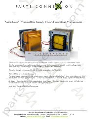
Balanced <strong>Input</strong> Mic Amp<br />
<strong>LME49880</strong><br />
30059643<br />
Illustration is:<br />
V0 = 101(V2 − V1)<br />
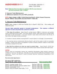
Active Crossover Network for Loudspeaker<br />
300596r8<br />
11 www.national.com
<strong>LME49880</strong><br />
Revision History<br />
Rev Date Description<br />
1.0 12/16/09 Initial released.<br />
1.01 01/08/10 <strong>Input</strong> text edits.<br />
1.02 03/22/10<br />
Edited the scaling (Y-axis) on the THD+N curves to match the limits described<br />
in the datasheet.<br />
www.national.com 12
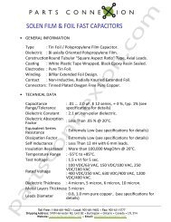
Physical Dimensions inches (millimeters) unless otherwise noted<br />
<strong>LME49880</strong><br />
Narrow PSOP Package<br />
Order Number <strong>LME49880</strong>MR<br />
NS Package Number MRA08B<br />
13 www.national.com
<strong>LME49880</strong> <strong>Dual</strong> FET <strong>Input</strong> Audio Operational Amplifier<br />
Notes<br />
For more National Semiconductor product information and proven design tools, visit the following Web sites at:<br />
www.national.com<br />
Products<br />
Design Support<br />
Amplifiers www.national.com/amplifiers WEBENCH® Tools www.national.com/webench<br />
Audio www.national.com/audio App Notes www.national.com/appnotes<br />
Clock and Timing www.national.com/timing Reference Designs www.national.com/refdesigns<br />
Data Converters www.national.com/adc Samples www.national.com/samples<br />
Interface www.national.com/interface Eval Boards www.national.com/evalboards<br />
LVDS www.national.com/lvds Packaging www.national.com/packaging<br />
Power Management www.national.com/power Green Compliance www.national.com/quality/green<br />
Switching Regulators www.national.com/switchers Distributors www.national.com/contacts<br />
LDOs www.national.com/ldo Quality and Reliability www.national.com/quality<br />
LED Lighting www.national.com/led Feedback/Support www.national.com/feedback<br />
Voltage References www.national.com/vref Design Made Easy www.national.com/easy<br />
PowerWise® Solutions www.national.com/powerwise Applications & Markets www.national.com/solutions<br />
Serial Digital Interface (SDI) www.national.com/sdi Mil/Aero www.national.com/milaero<br />
Temperature Sensors www.national.com/tempsensors SolarMagic www.national.com/solarmagic<br />
PLL/VCO www.national.com/wireless PowerWise® Design<br />
University<br />
www.national.com/training<br />
THE CONTENTS OF THIS DOCUMENT ARE PROVIDED IN CONNECTION WITH NATIONAL SEMICONDUCTOR CORPORATION<br />
(“NATIONAL”) PRODUCTS. NATIONAL MAKES NO REPRESENTATIONS OR WARRANTIES WITH RESPECT TO THE ACCURACY<br />
OR COMPLETENESS OF THE CONTENTS OF THIS PUBLICATION AND RESERVES THE RIGHT TO MAKE CHANGES TO<br />
SPECIFICATIONS AND PRODUCT DESCRIPTIONS AT ANY TIME WITHOUT NOTICE. NO LICENSE, WHETHER EXPRESS,<br />
IMPLIED, ARISING BY ESTOPPEL OR OTHERWISE, TO ANY INTELLECTUAL PROPERTY RIGHTS IS GRANTED BY THIS<br />
DOCUMENT.<br />
TESTING AND OTHER QUALITY CONTROLS ARE USED TO THE EXTENT NATIONAL DEEMS NECESSARY TO SUPPORT<br />
NATIONAL’S PRODUCT WARRANTY. EXCEPT WHERE MANDATED BY GOVERNMENT REQUIREMENTS, TESTING OF ALL<br />
PARAMETERS OF EACH PRODUCT IS NOT NECESSARILY PERFORMED. NATIONAL ASSUMES NO LIABILITY FOR<br />
APPLICATIONS ASSISTANCE OR BUYER PRODUCT DESIGN. BUYERS ARE RESPONSIBLE FOR THEIR PRODUCTS AND<br />
APPLICATIONS USING NATIONAL COMPONENTS. PRIOR TO USING OR DISTRIBUTING ANY PRODUCTS THAT INCLUDE<br />
NATIONAL COMPONENTS, BUYERS SHOULD PROVIDE ADEQUATE DESIGN, TESTING AND OPERATING SAFEGUARDS.<br />
EXCEPT AS PROVIDED IN NATIONAL’S TERMS AND CONDITIONS OF SALE FOR SUCH PRODUCTS, NATIONAL ASSUMES NO<br />
LIABILITY WHATSOEVER, AND NATIONAL DISCLAIMS ANY EXPRESS OR IMPLIED WARRANTY RELATING TO THE SALE<br />
AND/OR USE OF NATIONAL PRODUCTS INCLUDING LIABILITY OR WARRANTIES RELATING TO FITNESS FOR A PARTICULAR<br />
PURPOSE, MERCHANTABILITY, OR INFRINGEMENT OF ANY PATENT, COPYRIGHT OR OTHER INTELLECTUAL PROPERTY<br />
RIGHT.<br />
LIFE SUPPORT POLICY<br />
NATIONAL’S PRODUCTS ARE NOT AUTHORIZED FOR USE AS CRITICAL COMPONENTS IN LIFE SUPPORT DEVICES OR<br />
SYSTEMS WITHOUT THE EXPRESS PRIOR WRITTEN APPROVAL OF THE CHIEF EXECUTIVE OFFICER AND GENERAL<br />
COUNSEL OF NATIONAL SEMICONDUCTOR CORPORATION. As used herein:<br />
Life support devices or systems are devices which (a) are intended for surgical implant into the body, or (b) support or sustain life and<br />
whose failure to perform when properly used in accordance with instructions for use provided in the labeling can be reasonably expected<br />
to result in a significant injury to the user. A critical component is any component in a life support device or system whose failure to perform<br />
can be reasonably expected to cause the failure of the life support device or system or to affect its safety or effectiveness.<br />
National Semiconductor and the National Semiconductor logo are registered trademarks of National Semiconductor Corporation. All other<br />
brand or product names may be trademarks or registered trademarks of their respective holders.<br />
Copyright© 2010 National Semiconductor Corporation<br />
For the most current product information visit us at www.national.com<br />
National Semiconductor<br />
Americas Technical<br />
Support Center<br />
Email: support@nsc.com<br />
Tel: 1-800-272-9959<br />
National Semiconductor Europe<br />
Technical Support Center<br />
Email: europe.support@nsc.com<br />
National Semiconductor Asia<br />
Pacific Technical Support Center<br />
Email: ap.support@nsc.com<br />
National Semiconductor Japan<br />
Technical Support Center<br />
Email: jpn.feedback@nsc.com<br />
www.national.com
IMPORTANT NOTICE<br />
Texas Instruments Incorporated and its subsidiaries (TI) reserve the right to make corrections, modifications, enhancements, improvements,<br />
and other changes to its products and services at any time and to discontinue any product or service without notice. Customers should<br />
obtain the latest relevant information before placing orders and should verify that such information is current and complete. All products are<br />
sold subject to TI’s terms and conditions of sale supplied at the time of order acknowledgment.<br />
TI warrants performance of its hardware products to the specifications applicable at the time of sale in accordance with TI’s standard<br />
warranty. Testing and other quality control techniques are used to the extent TI deems necessary to support this warranty. Except where<br />
mandated by government requirements, testing of all parameters of each product is not necessarily performed.<br />
TI assumes no liability for applications assistance or customer product design. Customers are responsible for their products and<br />
applications using TI components. To minimize the risks associated with customer products and applications, customers should provide<br />
adequate design and operating safeguards.<br />
TI does not warrant or represent that any license, either express or implied, is granted under any TI patent right, copyright, mask work right,<br />
or other TI intellectual property right relating to any combination, machine, or process in which TI products or services are used. Information<br />
published by TI regarding third-party products or services does not constitute a license from TI to use such products or services or a<br />
warranty or endorsement thereof. Use of such information may require a license from a third party under the patents or other intellectual<br />
property of the third party, or a license from TI under the patents or other intellectual property of TI.<br />
Reproduction of TI information in TI data books or data sheets is permissible only if reproduction is without alteration and is accompanied<br />
by all associated warranties, conditions, limitations, and notices. Reproduction of this information with alteration is an unfair and deceptive<br />
business practice. TI is not responsible or liable for such altered documentation. Information of third parties may be subject to additional<br />
restrictions.<br />
Resale of TI products or services with statements different from or beyond the parameters stated by TI for that product or service voids all<br />
express and any implied warranties for the associated TI product or service and is an unfair and deceptive business practice. TI is not<br />
responsible or liable for any such statements.<br />
TI products are not authorized for use in safety-critical applications (such as life support) where a failure of the TI product would reasonably<br />
be expected to cause severe personal injury or death, unless officers of the parties have executed an agreement specifically governing<br />
such use. Buyers represent that they have all necessary expertise in the safety and regulatory ramifications of their applications, and<br />
acknowledge and agree that they are solely responsible for all legal, regulatory and safety-related requirements concerning their products<br />
and any use of TI products in such safety-critical applications, notwithstanding any applications-related information or support that may be<br />
provided by TI. Further, Buyers must fully indemnify TI and its representatives against any damages arising out of the use of TI products in<br />
such safety-critical applications.<br />
TI products are neither designed nor intended for use in military/aerospace applications or environments unless the TI products are<br />
specifically designated by TI as military-grade or "enhanced plastic." Only products designated by TI as military-grade meet military<br />
specifications. Buyers acknowledge and agree that any such use of TI products which TI has not designated as military-grade is solely at<br />
the Buyer's risk, and that they are solely responsible for compliance with all legal and regulatory requirements in connection with such use.<br />
TI products are neither designed nor intended for use in automotive applications or environments unless the specific TI products are<br />
designated by TI as compliant with ISO/TS 16949 requirements. Buyers acknowledge and agree that, if they use any non-designated<br />
products in automotive applications, TI will not be responsible for any failure to meet such requirements.<br />
Following are URLs where you can obtain information on other Texas Instruments products and application solutions:<br />
Products<br />
Applications<br />
Audio www.ti.com/audio Communications and Telecom www.ti.com/communications<br />
Amplifiers amplifier.ti.com Computers and Peripherals www.ti.com/computers<br />
Data Converters dataconverter.ti.com Consumer Electronics www.ti.com/consumer-apps<br />
DLP® Products www.dlp.com Energy and Lighting www.ti.com/energy<br />
DSP dsp.ti.com Industrial www.ti.com/industrial<br />
Clocks and Timers www.ti.com/clocks Medical www.ti.com/medical<br />
Interface interface.ti.com Security www.ti.com/security<br />
Logic logic.ti.com Space, Avionics and Defense www.ti.com/space-avionics-defense<br />
Power Mgmt power.ti.com Transportation and Automotive www.ti.com/automotive<br />
Microcontrollers microcontroller.ti.com Video and Imaging www.ti.com/video<br />
RFID<br />
OMAP Mobile Processors<br />
Wireless Connectivity<br />
www.ti-rfid.com<br />
www.ti.com/omap<br />
www.ti.com/wirelessconnectivity<br />
TI E2E Community Home Page<br />
e2e.ti.com<br />
Mailing Address: Texas Instruments, Post Office Box 655303, Dallas, Texas 75265<br />
Copyright © 2011, Texas Instruments Incorporated