Replace the Power Supply Module - Transition Networks
Replace the Power Supply Module - Transition Networks
Replace the Power Supply Module - Transition Networks

You also want an ePaper? Increase the reach of your titles
YUMPU automatically turns print PDFs into web optimized ePapers that Google loves.
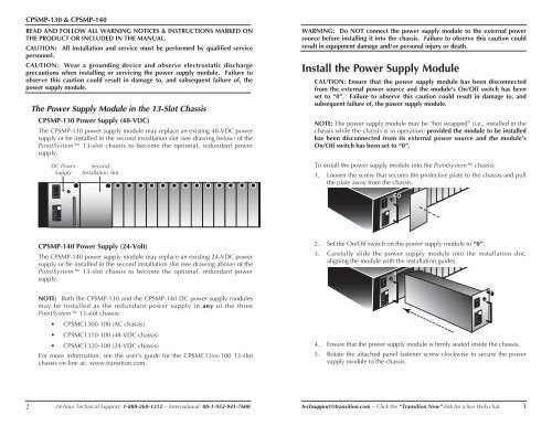
CPSMP-130 & CPSMP-140<br />
READ AND FOLLOW ALL WARNING NOTICES & INSTRUCTIONS MARKED ON<br />
THE PRODUCT OR INCLUDED IN THE MANUAL.<br />
CAUTION: All installation and service must be performed by qualified service<br />
personnel.<br />
CAUTION: Wear a grounding device and observe electrostatic discharge<br />
precautions when installing or servicing <strong>the</strong> power supply module. Failure to<br />
observe this caution could result in damage to, and subsequent failure of, <strong>the</strong><br />
power supply module.<br />
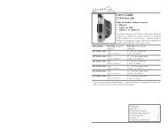
The <strong>Power</strong> <strong>Supply</strong> <strong>Module</strong> in <strong>the</strong> 13-Slot Chassis<br />
CPSMP-130 <strong>Power</strong> <strong>Supply</strong> (48-VDC)<br />
The CPSMP-130 power supply module may replace an existing 48-VDC power<br />
supply or be installed in <strong>the</strong> second installation slot (see drawing below) of <strong>the</strong><br />
PointSystem 13-slot chassis to become <strong>the</strong> optional, redundant power<br />
supply.<br />
WARNING: Do NOT connect <strong>the</strong> power supply module to <strong>the</strong> external power<br />
source before installing it into <strong>the</strong> chassis. Failure to observe this caution could<br />
result in equipment damage and/or personal injury or death.<br />
Install <strong>the</strong> <strong>Power</strong> <strong>Supply</strong> <strong>Module</strong><br />
CAUTION: Ensure that <strong>the</strong> power supply module has been disconnected<br />
from <strong>the</strong> external power source and <strong>the</strong> module’s On/Off switch has been<br />
set to “0”. Failure to observe this caution could result in damage to, and<br />
subsequent failure of, <strong>the</strong> power supply module.<br />
NOTE: The power supply module may be “hot swapped” (i.e., installed in <strong>the</strong><br />
chassis while <strong>the</strong> chassis is in operation) provided <strong>the</strong> module to be installed<br />
has been disconnected from its external power source and <strong>the</strong> module’s<br />
On/Off switch has been set to “0”.<br />
DC <strong>Power</strong><br />
<strong>Supply</strong><br />
I<br />
0<br />
Second<br />
Installation Slot<br />
To install <strong>the</strong> power supply module into <strong>the</strong> PointSystem chassis:<br />
1. Loosen <strong>the</strong> screw that secures <strong>the</strong> protective plate to <strong>the</strong> chassis and pull<br />
<strong>the</strong> plate away from <strong>the</strong> chassis.<br />
I<br />
0<br />
- +<br />
- +<br />
CPSMP-140 <strong>Power</strong> <strong>Supply</strong> (24-Volt)<br />
The CPSMP-140 power supply module may replace an existing 24-VDC power<br />
supply or be installed in <strong>the</strong> second installation slot (see drawing above) of <strong>the</strong><br />
PointSystem 13-slot chassis to become <strong>the</strong> optional, redundant power<br />
supply.<br />
2. Set <strong>the</strong> On/Off switch on <strong>the</strong> power supply module to “0”.<br />
3. Carefully slide <strong>the</strong> power supply module into <strong>the</strong> installation slot,<br />
aligning <strong>the</strong> module with <strong>the</strong> installation guides.<br />
I<br />
0<br />
NOTE: Both <strong>the</strong> CPSMP-130 and <strong>the</strong> CPSMP-140 DC power supply modules<br />
may be installed as <strong>the</strong> redundant power supply in any of <strong>the</strong> three<br />
PointSystem 13-slot chassis:<br />
• CPSMC1300-100 (AC chassis)<br />
• CPSMC1310-100 (48-VDC chassis)<br />
• CPSMC1320-100 (24-VDC chassis)<br />
For more information, see <strong>the</strong> user’s guide for <strong>the</strong> CPSMC13xx-100 13-slot<br />
chassis on-line at: www.transition.com.<br />
- +<br />
4. Ensure that <strong>the</strong> power supply module is firmly seated inside <strong>the</strong> chassis.<br />
5. Rotate <strong>the</strong> attached panel fastener screw clockwise to secure <strong>the</strong> power<br />
supply module to <strong>the</strong> chassis.<br />
I<br />
0<br />
- +<br />
2 24-hour Technical Support: 1-800-260-1312 -- International: 00-1-952-941-7600<br />
techsupport@transition.com -- Click <strong>the</strong> “<strong>Transition</strong> Now” link for a live Web chat.<br />
3