Replace the Power Supply Module - Transition Networks
Replace the Power Supply Module - Transition Networks
Replace the Power Supply Module - Transition Networks

Create successful ePaper yourself
Turn your PDF publications into a flip-book with our unique Google optimized e-Paper software.
- +<br />
+<br />
I<br />
0<br />
+<br />
+<br />
+<br />
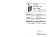
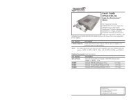
User’s Guide<br />
CPSMP-130<br />
48-VDC <strong>Power</strong> <strong>Supply</strong> <strong>Module</strong><br />
CPSMP-140<br />
24-VDC <strong>Power</strong> <strong>Supply</strong> <strong>Module</strong><br />
13-Slot PointSystem Accessory<br />
The <strong>Transition</strong> <strong>Networks</strong> CPSMP-130 power supply is a 48-VDC slide-in-module<br />
that provides optional, redundant power to <strong>the</strong> CPSMC1310-100 13-slot<br />
PointSystem chassis and any installed media converter slide-in-modules and<br />
management modules.<br />
The <strong>Transition</strong> <strong>Networks</strong> CPSMP-140 power supply is a 24-VDC slide-in-module<br />
that provides optional, redundant power to <strong>the</strong> CPSMC1320-100 13-slot<br />
PointSystem chassis and any installed media converter slide-in-modules and<br />
management modules.<br />
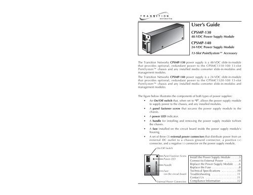
The figure below illustrates <strong>the</strong> components of both types of power supplies:<br />
• An On/Off switch that, when set to “I”, allows <strong>the</strong> power supply module<br />
to supply power to <strong>the</strong> chassis, and any installed modules.<br />
• A panel fastener screw that secures <strong>the</strong> power supply module to <strong>the</strong><br />
chassis.<br />
• A power LED indicator.<br />
• A handle for installing and removing <strong>the</strong> power supply module to/from<br />
<strong>the</strong> chassis.<br />
• A fuse installed on <strong>the</strong> circuit board inside <strong>the</strong> power supply module’s<br />
housing.<br />
• A set of three (3) external power connectors that distribute power from an<br />
external DC outlet to a chassis ground connector, a positive (+)<br />
connector, and a negative (-) connector on <strong>the</strong> power supply module.<br />
On/Off Switch<br />
I<br />
0<br />
- +<br />
Panel Fastener Screw<br />
<strong>Power</strong> LED<br />
Handle<br />
Fuse<br />
(on <strong>the</strong> circuit board<br />
External <strong>Power</strong> Connectors<br />
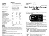
Install <strong>the</strong> <strong>Power</strong> <strong>Supply</strong> <strong>Module</strong> . . . . .3<br />
Connect to External <strong>Power</strong> . . . . . . . . .4<br />
<strong>Replace</strong> <strong>the</strong> <strong>Power</strong> <strong>Supply</strong> <strong>Module</strong> . . .6<br />
<strong>Replace</strong> <strong>the</strong> Fuse . . . . . . . . . . . . . . . . .8<br />
Technical Specifications . . . . . . . . . .10<br />
Troubleshooting . . . . . . . . . . . . . . . .11<br />
Contact Us . . . . . . . . . . . . . . . . . . . .11<br />
Compliance Information . . . . . . . . . .12
CPSMP-130 & CPSMP-140<br />
READ AND FOLLOW ALL WARNING NOTICES & INSTRUCTIONS MARKED ON<br />
THE PRODUCT OR INCLUDED IN THE MANUAL.<br />
CAUTION: All installation and service must be performed by qualified service<br />
personnel.<br />
CAUTION: Wear a grounding device and observe electrostatic discharge<br />
precautions when installing or servicing <strong>the</strong> power supply module. Failure to<br />
observe this caution could result in damage to, and subsequent failure of, <strong>the</strong><br />
power supply module.<br />
The <strong>Power</strong> <strong>Supply</strong> <strong>Module</strong> in <strong>the</strong> 13-Slot Chassis<br />
CPSMP-130 <strong>Power</strong> <strong>Supply</strong> (48-VDC)<br />
The CPSMP-130 power supply module may replace an existing 48-VDC power<br />
supply or be installed in <strong>the</strong> second installation slot (see drawing below) of <strong>the</strong><br />
PointSystem 13-slot chassis to become <strong>the</strong> optional, redundant power<br />
supply.<br />
WARNING: Do NOT connect <strong>the</strong> power supply module to <strong>the</strong> external power<br />
source before installing it into <strong>the</strong> chassis. Failure to observe this caution could<br />
result in equipment damage and/or personal injury or death.<br />
Install <strong>the</strong> <strong>Power</strong> <strong>Supply</strong> <strong>Module</strong><br />
CAUTION: Ensure that <strong>the</strong> power supply module has been disconnected<br />
from <strong>the</strong> external power source and <strong>the</strong> module’s On/Off switch has been<br />
set to “0”. Failure to observe this caution could result in damage to, and<br />
subsequent failure of, <strong>the</strong> power supply module.<br />
NOTE: The power supply module may be “hot swapped” (i.e., installed in <strong>the</strong><br />
chassis while <strong>the</strong> chassis is in operation) provided <strong>the</strong> module to be installed<br />
has been disconnected from its external power source and <strong>the</strong> module’s<br />
On/Off switch has been set to “0”.<br />
DC <strong>Power</strong><br />
<strong>Supply</strong><br />
I<br />
0<br />
Second<br />
Installation Slot<br />
To install <strong>the</strong> power supply module into <strong>the</strong> PointSystem chassis:<br />
1. Loosen <strong>the</strong> screw that secures <strong>the</strong> protective plate to <strong>the</strong> chassis and pull<br />
<strong>the</strong> plate away from <strong>the</strong> chassis.<br />
I<br />
0<br />
- +<br />
- +<br />
CPSMP-140 <strong>Power</strong> <strong>Supply</strong> (24-Volt)<br />
The CPSMP-140 power supply module may replace an existing 24-VDC power<br />
supply or be installed in <strong>the</strong> second installation slot (see drawing above) of <strong>the</strong><br />
PointSystem 13-slot chassis to become <strong>the</strong> optional, redundant power<br />
supply.<br />
2. Set <strong>the</strong> On/Off switch on <strong>the</strong> power supply module to “0”.<br />
3. Carefully slide <strong>the</strong> power supply module into <strong>the</strong> installation slot,<br />
aligning <strong>the</strong> module with <strong>the</strong> installation guides.<br />
I<br />
0<br />
NOTE: Both <strong>the</strong> CPSMP-130 and <strong>the</strong> CPSMP-140 DC power supply modules<br />
may be installed as <strong>the</strong> redundant power supply in any of <strong>the</strong> three<br />
PointSystem 13-slot chassis:<br />
• CPSMC1300-100 (AC chassis)<br />
• CPSMC1310-100 (48-VDC chassis)<br />
• CPSMC1320-100 (24-VDC chassis)<br />
For more information, see <strong>the</strong> user’s guide for <strong>the</strong> CPSMC13xx-100 13-slot<br />
chassis on-line at: www.transition.com.<br />
- +<br />
4. Ensure that <strong>the</strong> power supply module is firmly seated inside <strong>the</strong> chassis.<br />
5. Rotate <strong>the</strong> attached panel fastener screw clockwise to secure <strong>the</strong> power<br />
supply module to <strong>the</strong> chassis.<br />
I<br />
0<br />
- +<br />
2 24-hour Technical Support: 1-800-260-1312 -- International: 00-1-952-941-7600<br />
techsupport@transition.com -- Click <strong>the</strong> “<strong>Transition</strong> Now” link for a live Web chat.<br />
3
CPSMP-130 & CPSMP-140<br />
Connect to External <strong>Power</strong><br />
CAUTION: Ensure that external power source is NOT powered and that <strong>the</strong><br />
On/Off switch on <strong>the</strong> power supply module is set to “0” when connecting to<br />
<strong>the</strong> external power source. Failure to observe this caution could result in<br />
damage to, and subsequent failure of, <strong>the</strong> power supply module.<br />
48-VDC power supply<br />
• This product is intended to be used in a restricted access location. Proper<br />
earthing (grounding) is required to ensure safe operation and to comply<br />
with customer installation requirements and local electrical codes. Prior<br />
to installation, use a voltmeter/ohmmeter to check <strong>the</strong> wiring for <strong>the</strong><br />
presence of earth ground.<br />
• A readily accessible disconnect device as part of <strong>the</strong> building installation<br />
shall be incorporated into <strong>the</strong> fixed wiring. The disconnect device (a 48<br />
VDC, 15 or 20A circuit breaker or switch) must be included in <strong>the</strong><br />
ungrounded supply conductor. Overcurrent protection must be a 48<br />
VDC, 15 or 20A fuse or circuit breaker.<br />
24-VDC <strong>Power</strong> <strong>Supply</strong><br />
• This product is intended to be used in a restricted access location. Proper<br />
earthing (grounding) is required to ensure safe operation and to comply<br />
with customer installation requirements and local electrical codes. Prior<br />
to installation, use a voltmeter/ohmmeter to check <strong>the</strong> wiring for <strong>the</strong><br />
presence of earth ground.<br />
• A readily accessible disconnect device as part of <strong>the</strong> building installation<br />
shall be incorporated into <strong>the</strong> fixed wiring. The disconnect device (a 24<br />
VDC, 15 or 20A circuit breaker or switch) must be included in <strong>the</strong><br />
ungrounded supply conductor. Overcurrent protection must be a 24<br />
VDC, 15 or 20A fuse or circuit breaker.<br />
Connect to External <strong>Power</strong> -- Continued<br />
To power <strong>the</strong> CPSMP-130 or <strong>the</strong> CPSMP-140 power supply module:<br />
1. Set <strong>the</strong> On/Off switch on <strong>the</strong> power supply module to “0”.<br />
2. Verify that <strong>the</strong> external power source is NOT powered.<br />
3. Connect <strong>the</strong> positive (+) terminal to <strong>the</strong> external power connector marked<br />
“+”. Turn <strong>the</strong> terminal screw clockwise to secure.<br />
4. Connect <strong>the</strong> negative (-) terminal to <strong>the</strong> external power connector marked<br />
“-”. Turn <strong>the</strong> terminal screw clockwise to secure.<br />
5. Connect <strong>the</strong> ground terminal to <strong>the</strong> external power connector marked<br />
“chassis ground”. Turn <strong>the</strong> terminal screw clockwise to secure.<br />
6. Set <strong>the</strong> power supply module power switch to “I”.<br />
7. Verify that <strong>the</strong> power supply module is powered by observing <strong>the</strong><br />
illuminated power LED.<br />
I<br />
0<br />
- +<br />
GND<br />
–<br />
+<br />
On/Off<br />
Switch<br />
I<br />
0<br />
- +<br />
<strong>Power</strong> LED<br />
External <strong>Power</strong> Connectors<br />
Panel Fastener Screw<br />
4 24-hour Technical Support: 1-800-260-1312 -- International: 00-1-952-941-7600<br />
techsupport@transition.com -- Click <strong>the</strong> “<strong>Transition</strong> Now” link for a live Web chat.<br />
5
CPSMP-130 & CPSMP-140<br />
WARNING: Do NOT connect <strong>the</strong> power supply module to <strong>the</strong> external power<br />
source before installing it into <strong>the</strong> chassis. Failure to observe this caution could<br />
result in equipment damage and/or personal injury or death.<br />
<strong>Replace</strong> <strong>the</strong> <strong>Power</strong> <strong>Supply</strong> <strong>Module</strong><br />
CAUTION: Ensure that <strong>the</strong> power supply module has been disconnected<br />
from <strong>the</strong> external power source and <strong>the</strong> module’s On/Off switch has been<br />
set to “0”. Failure to observe this caution could result in damage to, and<br />
subsequent failure of, <strong>the</strong> power supply module.<br />
NOTE: The power supply module may be “hot swapped” (i.e., replaced while<br />
<strong>the</strong> chassis is in operation) provided <strong>the</strong> module to be replaced has been<br />
disconnected from its external power source and <strong>the</strong> module’s On/Off<br />
switch has been set to “0”.<br />
To replace <strong>the</strong> CPSMP-130 or <strong>the</strong> CPSMP-140 power supply module:<br />
1. Set <strong>the</strong> On/Off switch on <strong>the</strong> power supply module to “0”.<br />
2. Verify that <strong>the</strong> external power source is NOT powered.<br />
3. Disconnect <strong>the</strong> positive(+) terminal from <strong>the</strong> external power connector<br />
marked “+”.<br />
4. Disconnect <strong>the</strong> negative (-) terminal from <strong>the</strong> external power connector<br />
marked “-”.<br />
5. Disconnect <strong>the</strong> ground terminal from <strong>the</strong> external power connector<br />
marked “chassis ground”.<br />
6. Rotate <strong>the</strong> attached panel fastener screw counter-clockwise.<br />
<strong>Replace</strong> <strong>the</strong> <strong>Power</strong> <strong>Supply</strong> <strong>Module</strong> -- Continued<br />
8. Carefully slide <strong>the</strong> replacement power supply module into <strong>the</strong> installation<br />
slot, aligning <strong>the</strong> module with <strong>the</strong> installation guides.<br />
I<br />
0<br />
- +<br />
9. Ensure that <strong>the</strong> power supply module is firmly seated inside <strong>the</strong> chassis.<br />
10. Rotate <strong>the</strong> attached panel fastener screw clockwise to secure <strong>the</strong> power<br />
supply module to <strong>the</strong> chassis.<br />
11. See <strong>the</strong> “Connect to External <strong>Power</strong>” section (page 5) for instructions on<br />
re-connecting <strong>the</strong> power supply module to <strong>the</strong> external power source.<br />
I<br />
0<br />
- +<br />
I<br />
0<br />
On/Off<br />
Switch<br />
I<br />
0<br />
Panel Fastener Screw<br />
<strong>Power</strong> LED<br />
GND<br />
- +<br />
–<br />
- +<br />
+<br />
External <strong>Power</strong> Connectors<br />
7. Carefully slide <strong>the</strong> power supply to be replaced out of <strong>the</strong> chassis.<br />
I<br />
0<br />
- +<br />
I<br />
0<br />
- +<br />
6 24-hour Technical Support: 1-800-260-1312 -- International: 00-1-952-941-7600<br />
techsupport@transition.com -- Click <strong>the</strong> “<strong>Transition</strong> Now” link for a live Web chat.<br />
7
10BASE-2<br />
- +<br />
CPSMP-130 & CPSMP-140<br />
<strong>Replace</strong> <strong>the</strong> Fuse<br />
CAUTION: Ensure that <strong>the</strong> power supply module has been disconnected<br />
from <strong>the</strong> external power source and <strong>the</strong> module’s On/Off switch has been<br />
set to “0”. Failure to observe this caution could result in damage to, and<br />
subsequent failure of, <strong>the</strong> power supply module.<br />
NOTE: The power supply module may be “hot swapped” (i.e., serviced while<br />
<strong>the</strong> chassis is in operation) provided <strong>the</strong> module to be serviced has been<br />
disconnected from its external power supply and <strong>the</strong> module’s On/Off<br />
switch has been set to “0”.<br />
To replace <strong>the</strong> fuse in <strong>the</strong> CPSMP-130 or CPSMP-140 power supply module:<br />
1. Set <strong>the</strong> On/Off switch on <strong>the</strong> power supply module to “0”.<br />
2. Verify that <strong>the</strong> external power source is NOT powered.<br />
3. Disconnect <strong>the</strong> positive (+) DC terminal from <strong>the</strong> external power<br />
connector marked “+”.<br />
4. Disconnect <strong>the</strong> negative (-) DC terminal from <strong>the</strong> external power<br />
connector marked “-”.<br />
5. Disconnect <strong>the</strong> ground terminal from <strong>the</strong> external power connector<br />
marked “chassis ground”.<br />
I<br />
0<br />
- +<br />
GND<br />
–<br />
On/Off<br />
Switch<br />
I<br />
0<br />
- +<br />
Panel Fastener Screw<br />
<strong>Power</strong> LED<br />
WARNING: Do NOT connect <strong>the</strong> power supply module to <strong>the</strong> external power<br />
source before installing it into <strong>the</strong> chassis. Failure to observe this caution could<br />
result in equipment damage and/or personal injury or death.<br />
8. Remove <strong>the</strong> four (4) screws that secure <strong>the</strong> panel to <strong>the</strong> module (see <strong>the</strong><br />
drawing below) and remove <strong>the</strong> panel from module.<br />
I<br />
0<br />
+<br />
+<br />
I<br />
0<br />
Fuse location<br />
Remove <strong>the</strong>se four (4) screws<br />
to access <strong>the</strong> fuse<br />
+<br />
+<br />
9. The fuse is located inside <strong>the</strong> power supply module on <strong>the</strong> circuit board.<br />
Remove <strong>the</strong> fuse from <strong>the</strong> fuse holder.<br />
10. Install a same size and rating replacement fuse in <strong>the</strong> fuse holder.<br />
11. <strong>Replace</strong> <strong>the</strong> panel to <strong>the</strong> power supply module and secure it in place<br />
with <strong>the</strong> four (4) screws.<br />
12. Carefully slide <strong>the</strong> power supply module into <strong>the</strong> installation slot,<br />
aligning <strong>the</strong> module with <strong>the</strong> installation guides.<br />
+<br />
External <strong>Power</strong> Connectors<br />
6. Rotate <strong>the</strong> attached panel fastener screw counter-clockwise.<br />
7. Carefully slide <strong>the</strong> power supply module out of <strong>the</strong> chassis.<br />
I<br />
0<br />
- +<br />
I<br />
0<br />
I<br />
0<br />
- +<br />
- +<br />
I<br />
0<br />
- +<br />
13. Ensure that <strong>the</strong> power supply module is firmly seated inside <strong>the</strong> chassis.<br />
14. Rotate <strong>the</strong> attached panel fastener screw clockwise to secure <strong>the</strong> power<br />
supply module to <strong>the</strong> chassis.<br />
15. See <strong>the</strong> “Connect to External <strong>Power</strong>” section (page 5) for instructions on<br />
re-connecting <strong>the</strong> power supply module to <strong>the</strong> external power source.<br />
8 24-hour Technical Support: 1-800-260-1312 -- International: 00-1-952-941-7600<br />
techsupport@transition.com -- Click <strong>the</strong> “<strong>Transition</strong> Now” link for a live Web chat.<br />
9
CPSMP-130 & CPSMP-140<br />
Technical Specification<br />
For use with <strong>Transition</strong> <strong>Networks</strong> model CPSMP-130 or CPSMP-140 or equivalent.<br />
Standards<br />
UL Listed; FCC & CISPR Class A; CE Mark<br />
Dimensions<br />
3.4" x 2.5" x 11.0" (86 mm x 64 mm x 279 mm)<br />
Weight<br />
1.8 lb (0.8 kg) (approximate)<br />
CPSMP-130 <strong>Power</strong> Input: 48VDC (38 to 58VDC) @ 2.63Amp<br />
(typical for a fully-loaded chassis)<br />
<strong>Power</strong> Output: +12 VDC @ 12.5 Amp (maximum)<br />
CPSMP-140 <strong>Power</strong> Input: 24VDC (20 to 31VDC) @ 4.83 Amp<br />
(typical for a fully-loaded chassis)<br />
<strong>Power</strong> Output: +12 VDC @ 8.3 Amp (maximum)<br />
Fuse<br />
6.3Amp / 250V<br />
MTBF<br />
520,441 hours (MIL217F2 V5.0) (MIL-HDBK-217F)<br />
1,087,866 hours (Bellcore7 V5.0)<br />
Environment Tmra**: 0 to 50°C (32 to 122°F )<br />
Storage Temp: -20 to 85°C (-4 to 185°F)<br />
Humidity: 10 to 90%, non condensing<br />
Altitude: 0 to 10,000 feet<br />
Warranty<br />
Lifetime<br />
**Manufacturer’s rated ambient temperature: Tmra range for <strong>the</strong>se power supply<br />
modules depend on <strong>the</strong> physical characteristics and <strong>the</strong> installation configuration<br />
of <strong>the</strong> <strong>Transition</strong> <strong>Networks</strong> PointSystem chassis in which this slide-in-module<br />
will be installed.<br />
For <strong>the</strong> most up-to-date information on <strong>the</strong> CPSMP-130 and CPSMP-140 power<br />
supply modules, view <strong>the</strong> user’s guide on-line at: www.transition.com.<br />
10 24-hour Technical Support: 1-800-260-1312 -- International: 00-1-952-941-7600<br />
Troubleshooting<br />
If <strong>the</strong> power supply module fails, isolate and correct <strong>the</strong> failure by determining<br />
<strong>the</strong> answers to <strong>the</strong> following questions and <strong>the</strong>n taking <strong>the</strong> indicated action:<br />
1. Is <strong>the</strong> power LED on <strong>the</strong> power supply module illuminated?<br />
NO<br />
• Is <strong>the</strong> power supply module inserted properly into <strong>the</strong> chassis?<br />
• Is <strong>the</strong> power supply module properly connected to <strong>the</strong> external<br />
power source?<br />
• Does <strong>the</strong> external power source provide power?<br />
• Contact Technical Support: US/Canada: 1-800-260-1312,<br />
International: 00-1-952-941-7600.<br />
YES<br />
• Proceed to step 2.<br />
2. Is <strong>the</strong> fuse on <strong>the</strong> power supply intact?<br />
NO<br />
• CAUTION: See <strong>the</strong> “Replacing <strong>the</strong> Fuse” section (page 8) in this<br />
user’s guide for <strong>the</strong> proper method for replacing <strong>the</strong> fuse to <strong>the</strong><br />
power supply module.<br />
• Contact Technical Support: US/Canada: 1-800-260-1312,<br />
International: 00-1-952-941-7600.<br />
YES<br />
• Contact Technical Support: US/Canada: 1-800-260-1312,<br />
International: 00-1-952-941-7600.<br />
Contact Us<br />
Technical Support<br />
Technical support is available 24 hours a day.<br />
US and Canada: 1-800-260-1312<br />
International: 00-1-952-941-7600<br />
<strong>Transition</strong> Now<br />
Chat live via <strong>the</strong> Web with <strong>Transition</strong> <strong>Networks</strong> Technical Support.<br />
Log onto www.transition.com and click <strong>the</strong> <strong>Transition</strong> Now link.<br />
Web-Based Seminars<br />
<strong>Transition</strong> <strong>Networks</strong> provides seminars via live web-based training.<br />
Log onto www.transition.com and click <strong>the</strong> Learning Center link.<br />
E-Mail<br />
Ask a question anytime by sending an e-mail to our technical support staff.<br />
techsupport@transition.com<br />
Address<br />
<strong>Transition</strong> <strong>Networks</strong>, 6475 City West Parkway, Minneapolis, MN 55344, USA<br />
telephone: 952-941-7600, toll free: 800-526-9267, fax: 952-941-2322<br />
techsupport@transition.com -- Click <strong>the</strong> “<strong>Transition</strong> Now” link for a live Web chat. 11
Compliance Information<br />
UL Listed; C-UL Listed (Canada); CE Mark<br />
CISPR22/EN55022 Class A<br />
FCC Regulations<br />
This equipment has been tested and found to comply with <strong>the</strong> limits for a Class A digital<br />
device, pursuant to part 15 of <strong>the</strong> FCC rules. These limits are designed to provide reasonable<br />
protection against harmful interference when <strong>the</strong> equipment is operated in a commercial<br />
environment. This equipment generates, uses, and can radiate radio frequency energy and, if<br />
not installed and used in accordance with <strong>the</strong> instruction manual, may cause harmful<br />
interference to radio communications. Operation of this equipment in a residential area is<br />
likely to cause harmful interference, in which case <strong>the</strong> user will be required to correct <strong>the</strong><br />
interference at <strong>the</strong> user's own expense.<br />
Canadian Regulations<br />
This digital apparatus does not exceed <strong>the</strong> Class A limits for radio noise for digital apparatus<br />
set out on <strong>the</strong> radio interference regulations of <strong>the</strong> Canadian Department of Communications.<br />
Le présent appareil numérique n'émet pas de bruits radioélectriques dépassant les limites<br />
applicables aux appareils numériques de la Class A prescrites dans le Règlement sur le<br />
brouillage radioélectrique édicté par le ministère des Communications du Canada.<br />
European Regulations<br />
Warning This is a Class A product. In a domestic environment this product may cause radio<br />
interference in which case <strong>the</strong> user may be required to take adequate measures.<br />
Achtung! Dieses ist ein Gerät der Funkstörgrenzwertklasse A. In Wohnbereichen können<br />
bei Betrieb dieses Gerätes Rundfunkstörungen auftreten, in weichen Fällen der Benutzer für<br />
entsprechende Gegenmaßnahmen werantwortlich ist.<br />
Attention! Ceci est un produit de Classe A. Dans un environment domestique, ce produit<br />
risque de créer des interférences radioélectriques, il appartiendra alors à l'utilsateur de<br />
prende les measures spécifiques appropriées.<br />
Declaration of Conformity<br />
Name of Mfg: <strong>Transition</strong> <strong>Networks</strong><br />
6475 City West Parkway, Minneapolis MN 55344 USA<br />
Model:<br />
Redundant <strong>Power</strong> <strong>Supply</strong><br />
Part Number(s): CPSMP-130, CPSMP-140<br />
Regulation: EMC Directive 89/336/EEC<br />
Purpose: To declare that <strong>the</strong> CPSMP-130 and CPSMP-140 to which this<br />
declaration refers are in conformity with <strong>the</strong> following standards.<br />
EN 55022:1988 + A1:2000 Class A; FCC Part 15 subpart B; UL 1950<br />
I, <strong>the</strong> undersigned, hereby declare that <strong>the</strong> equipment specified above conforms to <strong>the</strong> above<br />
Directive(s) and Standard(s).<br />
Stephen Anderson, Vice-President of Engineering<br />
June 8, 2001<br />
Date<br />
Trademark Notice<br />
All trademarks and registered trademarks are <strong>the</strong> property of <strong>the</strong>ir respective owners.<br />
Copyright Restrictions<br />
© 2001, 2004 <strong>Transition</strong> <strong>Networks</strong>. All rights reserved. No part of this work may be<br />
reproduced or used in any form or by any means - graphic, electronic, or mechanical -<br />
without written permission from <strong>Transition</strong> <strong>Networks</strong>.<br />
Printed in <strong>the</strong> U.S.A. 33213.B