Replace the Power Supply Module - Transition Networks
Replace the Power Supply Module - Transition Networks
Replace the Power Supply Module - Transition Networks

You also want an ePaper? Increase the reach of your titles
YUMPU automatically turns print PDFs into web optimized ePapers that Google loves.
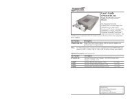
CPSMP-130 & CPSMP-140<br />
WARNING: Do NOT connect <strong>the</strong> power supply module to <strong>the</strong> external power<br />
source before installing it into <strong>the</strong> chassis. Failure to observe this caution could<br />
result in equipment damage and/or personal injury or death.<br />
<strong>Replace</strong> <strong>the</strong> <strong>Power</strong> <strong>Supply</strong> <strong>Module</strong><br />
CAUTION: Ensure that <strong>the</strong> power supply module has been disconnected<br />
from <strong>the</strong> external power source and <strong>the</strong> module’s On/Off switch has been<br />
set to “0”. Failure to observe this caution could result in damage to, and<br />
subsequent failure of, <strong>the</strong> power supply module.<br />
NOTE: The power supply module may be “hot swapped” (i.e., replaced while<br />
<strong>the</strong> chassis is in operation) provided <strong>the</strong> module to be replaced has been<br />
disconnected from its external power source and <strong>the</strong> module’s On/Off<br />
switch has been set to “0”.<br />
To replace <strong>the</strong> CPSMP-130 or <strong>the</strong> CPSMP-140 power supply module:<br />
1. Set <strong>the</strong> On/Off switch on <strong>the</strong> power supply module to “0”.<br />
2. Verify that <strong>the</strong> external power source is NOT powered.<br />
3. Disconnect <strong>the</strong> positive(+) terminal from <strong>the</strong> external power connector<br />
marked “+”.<br />
4. Disconnect <strong>the</strong> negative (-) terminal from <strong>the</strong> external power connector<br />
marked “-”.<br />
5. Disconnect <strong>the</strong> ground terminal from <strong>the</strong> external power connector<br />
marked “chassis ground”.<br />
6. Rotate <strong>the</strong> attached panel fastener screw counter-clockwise.<br />
<strong>Replace</strong> <strong>the</strong> <strong>Power</strong> <strong>Supply</strong> <strong>Module</strong> -- Continued<br />
8. Carefully slide <strong>the</strong> replacement power supply module into <strong>the</strong> installation<br />
slot, aligning <strong>the</strong> module with <strong>the</strong> installation guides.<br />
I<br />
0<br />
- +<br />
9. Ensure that <strong>the</strong> power supply module is firmly seated inside <strong>the</strong> chassis.<br />
10. Rotate <strong>the</strong> attached panel fastener screw clockwise to secure <strong>the</strong> power<br />
supply module to <strong>the</strong> chassis.<br />
11. See <strong>the</strong> “Connect to External <strong>Power</strong>” section (page 5) for instructions on<br />
re-connecting <strong>the</strong> power supply module to <strong>the</strong> external power source.<br />
I<br />
0<br />
- +<br />
I<br />
0<br />
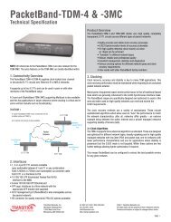
On/Off<br />
Switch<br />
I<br />
0<br />
Panel Fastener Screw<br />
<strong>Power</strong> LED<br />
GND<br />
- +<br />
–<br />
- +<br />
+<br />
External <strong>Power</strong> Connectors<br />
7. Carefully slide <strong>the</strong> power supply to be replaced out of <strong>the</strong> chassis.<br />
I<br />
0<br />
- +<br />
I<br />
0<br />
- +<br />
6 24-hour Technical Support: 1-800-260-1312 -- International: 00-1-952-941-7600<br />
techsupport@transition.com -- Click <strong>the</strong> “<strong>Transition</strong> Now” link for a live Web chat.<br />
7