Mic Kaczmarczik's TubeInformation - The Blue Guitar
Mic Kaczmarczik's TubeInformation - The Blue Guitar
Mic Kaczmarczik's TubeInformation - The Blue Guitar
Create successful ePaper yourself
Turn your PDF publications into a flip-book with our unique Google optimized e-Paper software.
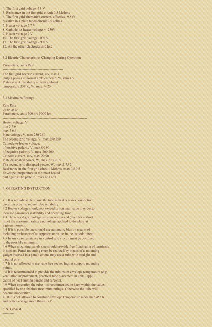
4. <strong>The</strong> first grid voltage -35 V<br />
5. Resistance in the first grid circuit 0.5 Mohms<br />
6. <strong>The</strong> first grid alternative current, effective, 9.8V;<br />
resistive in a plate tuned circuit 2.5 kohms<br />
7. Heater voltage 5.7 V<br />
8. Cathode-to-heater voltage +- 250V<br />
9. Heater voltage 7 V<br />
10. <strong>The</strong> first grid voltage -100 V<br />
11. <strong>The</strong> first grid voltage -200 V<br />
12. All the other electrodes are free<br />
3.2 Electric Characteristics Changing During Operation<br />
Parameters, units Rate<br />
----------------------------------------------------<br />
<strong>The</strong> first grid reverse current, uA, max 4<br />
Output power at normal ambient temp, W, min 4.5<br />
Plate current instability at high ambient<br />
temperature 358 K, % , max +- 25<br />
3.3 Maximum Ratings<br />
Rate Rate<br />
up to up to<br />
Parameters, units 500 hrs 5000 hrs<br />
------------------------------------------------------------------------<br />
Heater voltage, V:<br />
min 5.7 6<br />
max 7 6.6<br />
Plate voltage, V, max 250 250<br />
<strong>The</strong> second grid voltage, V, max 250 250<br />
Cathode-to-heater voltage:<br />
of positive polarity V, max 90 90<br />
of negative polarity V, max 200 200<br />
Cathode current, mA, max 90 90<br />
Plate dissipated power, W, max 20.5 20.5<br />
<strong>The</strong> second grid dissapted power, W, max 2.75 2<br />
Resistance in the first grid circuit, Mohms, max 0.5 0.5<br />
Envelope temperature in the most heated<br />
part against the plate, K, max 483 483<br />
4. OPERATING INSTRUCTION<br />
------------------------<br />
4.1 It is not advisable to use the tube in heater series connection<br />
circuit in order to secure tube reliability.<br />
4.2 Heater voltage should not exceedits nominal value in order to<br />
increase parameter instability and operating time.<br />
4.3 <strong>The</strong> second grid voltage must never exceed (even for a short<br />
time) the maximum rating and voltage applied to the plate at<br />
a given moment.<br />
4.4 If it is possible one should use automatic bias by means of<br />
including resistance of an appropriate value in the cathode circuit.<br />
4.5 In any case resistance in control grid circuit must be confined<br />
to the possible minimum.<br />
4.6 When mounting panels one should provide free floatinging of terminals<br />
in sockets. Panel mounting must be realized by means of a mounting<br />
gadget inserted in a panel; or one may use a tube with straight and<br />
parallel pins.<br />
4.7 It is not allowed to use tube free socket lugs as support mounting<br />
points.<br />
4.8 It is recommended to provide the minimum envelope temperature (e.g.<br />
ventilation improvement, practical tube placement in units, application<br />
of heat sinking panels and screens).<br />
4.9 When operation the tube it is recommended to keep within the values<br />
specified by the absolute maximum ratings. Otherwise the tube will<br />
become inoperative.<br />
4.10 It is not allowed to combine envelope temperature more than 453 K<br />
and heater voltage more than 6.3 V.<br />
5. STORAGE<br />
----------


