CKR 5xxx - Einzelmultischalter (24 - 32 Ausgänge) - Triax
CKR 5xxx - Einzelmultischalter (24 - 32 Ausgänge) - Triax
CKR 5xxx - Einzelmultischalter (24 - 32 Ausgänge) - Triax

You also want an ePaper? Increase the reach of your titles
YUMPU automatically turns print PDFs into web optimized ePapers that Google loves.
Zur Trennung der terrestrischen und der SAT-ZF-Signale, sind an den Ausgängen Antennendosen<br />
einzusetzen.<br />
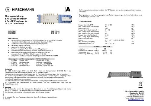
Montageanleitung<br />
SAT-ZF Multischalter<br />
4 Sat-ZF-Eingänge für<br />
<strong>24</strong> - <strong>32</strong> Teilnehmer<br />
<strong>CKR</strong> 5<strong>24</strong>1 940-159-001<br />
<strong>CKR</strong> 5<strong>32</strong>1 940-160-001<br />
Beschreibung<br />
• aktiver SAT-ZF-Multischalter mit 4 SAT-Eingängen für <strong>24</strong> und <strong>32</strong> SAT-Receiver<br />
• eingebauter 22kHz Generator zum Einsatz an Quattro „S“ LNCs<br />
• zusätzliche Einspeisung terrestrischer Signale (regelbar)<br />
• aktiver Rückkanal 5 - 65 MHz<br />
• geeignet für alle üblichen LNCs<br />
• terr. Vorwärtspfad in Push-Pull-Technik mit Pegelsteller<br />
• das integrierte Netzteil versorgt auch die angeschlossenen LNCs<br />
• unabhängiges Schalten der Receiver auf die 4 SAT-Ebenen<br />
Auswahlkriterium: 13 / 18 V, Schaltfrequenz 0 / 22 kHz<br />
• geeignet für Analog- und Digital-Empfang (terrestrisch DVB-T und SAT)<br />
Die angegebenen max. Ausgangspegel an den Teilnehmerausgängen sind einzuhalten, da es sonst<br />
zu Bildstörungen kommen kann.<br />
Technische Daten :<br />
Frequenzbereich, SAT 950 - <strong>24</strong>00 MHz<br />
Max. Ausg.-Pegel (35 dB IMA3) 90 dBµV<br />
Entkopplung H/V > 20 dB<br />
Frequenzbereich, terrestrisch 80 - 862 MHz<br />
Max. Ausg.-Pegel (60 dB IMA2) 76 dBµV<br />
Max. Ausg.-Pegel (60 dB IMA3) 85 dBµV<br />
Frequenzbereich, Rückkanal 5 - 65 MHz<br />
Max. Ausg.-Pegel (60 dB IMA3) 112 dBµV<br />
Entkopplung, Rec-Rec > 25 dB<br />
Netzteil 94 … 265 V~ / 47-63 Hz, 26 W<br />
Max. Stromabgabe (LNB) 500 mA<br />
Abmessungen L x B x H<br />
450 x 125 x 80 mm<br />
<strong>CKR</strong> 5<strong>24</strong>1 <strong>CKR</strong> 5<strong>32</strong>1<br />
Ausgänge <strong>24</strong> <strong>32</strong><br />
Dämpfung (Rückkanal) 13 +/-2 14 +/- 2 dB<br />
Verstärkung (terr.) 1 +/-2 0 +/- 2 dB<br />
Verstärkung (SAT-ZF) 1 +/-2 1 +/- 2 dB<br />
Steuersignal ASTRA analog / digital ASTRA / EUTELSAT<br />
13 V / 0 kHz Vertikal / low Vertikal / low ASTRA<br />
18 V / 0 kHz Horizontal / low Horizontal / low ASTRA<br />
13 V / 22 kHz Vertikal / high Vertikal / low EUTELSAT<br />
18 V / 22 kHz Horizontal / high Horizontal / low EUTELSAT<br />
50/51135.00 01/2006<br />
Sicherheit<br />
Die VDE-Bestimmungen 0100 und 0855 Teil 1 bzw. die Europanormen EN50083 Teil 1 zur<br />
Gewährleistung der elektrischen Sicherheit sind zu berücksichtigen!<br />
Nationale genehmigungsrechtliche Regelungen für Rundfunk-Empfangsanlagen sind zu beachten!<br />
Zur Vermeidung von Störungen benachbarter Anlagen/Systeme oder des eigenen Empfangs ist die<br />
Montage der koaxialen Verbinder (F-Connectoren) sorgfältig und fachgerecht durchzuführen.<br />
Hierbei sind Kurzschlüsse zu vermeiden.<br />
Vor Öffnen Netzstecker ziehen. Installationsarbeiten nur bei gezogenem Netzstecker durchführen.<br />
Vor Einstecken des Netzsteckers ist sicherzustellen, daß die angebrachten Kabel frei von<br />
Kurzschlüssen sind.<br />
Montage<br />
Der Multischalter ist mit den beiliegenden Schrauben an vor Feuchtigkeit geschützter und ebener<br />
Fläche zu montieren. Der Montageuntergrund sollte schwer entflammbar sein.<br />
Die Montage soll möglichst in Standortnähe der SAT-Antenne erfolgen.<br />
Unbenutzte Ein- bzw. Ausgänge müssen mit einem Endwiderstand abgeschlossen<br />
werden.<br />
Hirschmann Multimedia<br />
Electronics GmbH<br />
Stuttgarter Str. 45-51<br />
D-72654 Neckartenzlingen<br />
Phone:+49 (0) 180 <strong>32</strong> <strong>32</strong>-341<br />
www.hirschmann.com
Installation manual<br />
Multiswitch with<br />
4 Sat-IF-inputs<br />
for <strong>24</strong> - <strong>32</strong> subscribers<br />
<strong>CKR</strong> 5<strong>24</strong>1 940-159-001<br />
<strong>CKR</strong> 5<strong>32</strong>1 940-160-001<br />
Description<br />
• active SAT-IF-Multiswitch with 4 SAT-inputs for <strong>24</strong> and <strong>32</strong> SAT-receivers<br />
• with additional 22 kHz-generator for use with Quattro „S“ LNBs<br />
• additional feed-in for terrestrial signals (with variable attenuator)<br />
• active return path 5 - 65 MHz<br />
• suitable for all usual LNBs<br />
• terrestrial forward path with push-pull amplifier and variable attenuator<br />
• the integrated power-pack supplies the SEM and the connected LNBs<br />
• independent switching of the receiver to each of the 4 satellite polarizations<br />
switching criteria: 13 / 18 V, switch tone 0 / 22 kHz<br />
• suitable for analogue and digital reception (terrestrial DVB-T and SAT)<br />
switching criteria ASTRA analogue / digital ASTRA / EUTELSAT<br />
13 V / 0 kHz Vertikal / low Vertikal / low ASTRA<br />
18 V / 0 kHz Horizontal / low Horizontal / low ASTRA<br />
13 V / 22 kHz Vertikal / high Vertikal / low EUTELSAT<br />
18 V / 22 kHz Horizontal / high Horizontal / low EUTELSAT<br />
Security<br />
Repair and maintenance should only be done by skilled technicians and TV and radio specialists.<br />
The applicable European Standards and national requirements to ensure electrical security have to<br />
be obeyed. Likewise national standards and requirements for radio and TV receiving installations.<br />
Both the input level of the terrestrial and the SAT-IF-signals should be in the recommended ranges<br />
to avoid interference.<br />
Technical data:<br />
Frequency range SAT-IF 950 - <strong>24</strong>00 MHz<br />
Max. Output level (35 dB IMA3) 90 dBµV<br />
Isolation H/V > 20 dB<br />
Frequency range terrestrial 80 - 862 MHz<br />
Max. Output level (60 dB IMA2) 76 dBµV<br />
Max. Output level (60 dB IMA3) 85 dBµV<br />
Frequency range return path 5 - 65 MHz<br />
Max. Output level (60 dB IMA3) 112 dBµV<br />
Isolation, Rec-Rec > 25 dB<br />
Power supply unit (Switch-mode PSU) 94 … 265 V~ / 47-63 Hz, 26 W<br />
Max. current supply (to LNB) 500 mA<br />
Dimensions L x W x H<br />
450 x 125 x 80 mm<br />
<strong>CKR</strong> 5<strong>24</strong>1 <strong>CKR</strong> 5<strong>32</strong>1<br />
Outputs <strong>24</strong> <strong>32</strong><br />
Tap loss (return path) 13 +/-2 14 +/- 2 dB<br />
Tap gain (terrestrial) 1 +/-2 0 +/- 2 dB<br />
Tap gain (SAT-IF) 1 +/-2 1 +/- 2 dB<br />
Installation<br />
All installation and fixing of components should only be executed when the units are disconnected from<br />
the mains supply.<br />
The surface and environment of installation should be<br />
- even and dust-free<br />
- protected against humidity<br />
- flame proof<br />
- not under direct impact of sunlight<br />
- not adjacent to heating sources<br />
Ventilation slots should be kept open and suitable circulation of fresh air should be ensured.<br />
The installation has to be careful and skilful.<br />
Short-circuits have to be avoided. Only F- connectors matching with the used coaxial cable should be<br />
used. Not connected outputs of distribution units should be terminated with 75 Ohm termination<br />
resistors.<br />
In order to split the terrestrial signals and the satellite-IF-signals again, antenna sockets should be<br />
installed.<br />
The maximum output level at the receiver outputs mentioned should be adhered to in order to avoid<br />
picture disturbances.<br />
Hirschmann Multimedia<br />
Electronics GmbH<br />
Stuttgarter Str. 45-51<br />
D-72654 Neckartenzlingen<br />
Phone:+49 (0) 180 <strong>32</strong> <strong>32</strong>-341<br />
www.hirschmann.com