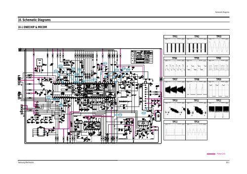
10. Schematic Diagrams
10. Schematic Diagrams
10. Schematic Diagrams

You also want an ePaper? Increase the reach of your titles
YUMPU automatically turns print PDFs into web optimized ePapers that Google loves.
<strong>Schematic</strong> <strong>Diagrams</strong><br />
<strong>10.</strong> <strong>Schematic</strong> <strong>Diagrams</strong><br />
10-1 ONECHIP & MICOM<br />
TP01<br />
TP02<br />
TP03<br />
TP04<br />
TP05<br />
TP06<br />
TP11<br />
TP04<br />
TP03<br />
TP05<br />
TP12<br />
TP10<br />
TP08<br />
TP09<br />
TP06<br />
TP13<br />
TP07<br />
TP08<br />
TP09<br />
TP01<br />
TP10<br />
TP11<br />
TP12<br />
TP02<br />
TP14<br />
TP07<br />
TP13<br />
TP14<br />
: Power Line<br />
Samsung Electronics<br />
10-1
<strong>Schematic</strong> <strong>Diagrams</strong><br />
10-2 SOUND, EXT-A/V (RCA)<br />
TP01<br />
TP01<br />
TP02<br />
TP02<br />
21 PIN-BUS<br />
: Power Line<br />
10-2 Samsung Electronics
<strong>Schematic</strong> <strong>Diagrams</strong><br />
10-3 SOUND, EXT-A/V (SCART)<br />
TP01<br />
TP01<br />
TP02<br />
TP02<br />
B+BUS<br />
: Power Line<br />
Samsung Electronics<br />
10-3
<strong>Schematic</strong> <strong>Diagrams</strong><br />
10-4 POWER / CRT / VERTICAL / HORIZONTAL<br />
TP01<br />
TP02<br />
TP03<br />
TP06<br />
TP05<br />
TP04<br />
TP03<br />
TP05<br />
TP02<br />
TP04<br />
TP01<br />
TP06<br />
: Power Line<br />
10-4 Samsung Electronics
Alignment and Adjustments<br />
4. Alignment and Adjustments<br />
4-1 Preadjustment<br />
4-1-1 Factory Mode<br />
1. Do not attempt these adjustments in the Video<br />
Mode.<br />
2. The Factory Mode adjustments are necessary<br />
when either the EEPROM (IC902) or the CRT<br />
is replaced.<br />
3. Do not tamper with the “Adjustment” screen<br />
of the Factory Mode menu. This screen is<br />
intended only for factory use.<br />
4-1-2 When EEPROM (IC902) Is Replaced<br />
1. When IC902 is replaced all adjustment data<br />
revert to initial values. It is necessary to<br />
re-program this data.<br />
2. After IC902 is replaced, warm up the TV for<br />
10 seconds.<br />
4-1-3 When CRT Is Replaced<br />
1. Make the following adjustments AFTER setting<br />
up after setting up purity and convergence<br />
:<br />
White Balance<br />
Sub-Brightness<br />
Vertical Center<br />
Vertical Size<br />
Horizontal Size<br />
Fail Safe (This adjustment must be the last<br />
step).<br />
2. If the EEPROM or CRT is replaced, set PVA to<br />
40 (factory mode) and set SC as follows.<br />
14 inch : 0<br />
20 inch : 9<br />
21 inch : 9<br />
4-2 Factory/Service Mode<br />
4-2-1 Procedure for the “Adjustment” Mode<br />
1. This mode uses the standard remote control.<br />
The Service Mode is activated by entering the<br />
following remote-control sequence :<br />
(1) DISPLAY→FACTORY.<br />
(2) STAND-BY→ DISPLAY→ MENU→ MUTE<br />
→POWER ON.<br />
2. The “SERVICE (FACTORY)” message will be<br />
displayed. The Service Mode has four components:<br />
ADJUST, OPTION and Reset.<br />
3. Access the Adjustment Mode by pressing the<br />
“VOLUME” keys ( Up or Down). The adjustment<br />
parameters are listed in the accompanying<br />
table, and selected by pressing the CHAN-<br />
NEL keys (▲ ,▼).<br />
4. Selection sequences for the all system:<br />
DOWN or UP key:<br />
SCT>SBT>BLR>BLB>RG>GG>BG>VSL><br />
VS>VA>HS>SC>SDL>STT>SSP>PDL><br />
NDL>PSR>NSR>AGC>VOL>LCO>TXP<br />
5. The VOLUME keys increase or decrease the<br />
adjustment values (stored in the<br />
non-volatile memory) when Adjustment Mode<br />
is cancelled.<br />
6. Cancel the Adjustment Mode by re-pressing<br />
the “FACTORY” or “Power OFF” keys.<br />
Samsung Electronics 4-1
Alignment and Adjustments<br />
4-2-2 Main Adjustment Parameter<br />
OSD FUNCTION RANGE INITIAL DATA REMARK<br />
SCT Sub Cont ras t 0 ~ 23<br />
SBT Sub Bright nes s 0 ~ 23<br />
BLR Black Level of fset Blue 0 ~ 15<br />
BLB Black Level of fset Red 0 ~ 15<br />
RG Red Gain 0 ~ 63<br />
GG Green Gain 0 ~ 63<br />
BG Blue Gai n 0 ~ 63<br />
VSL Ver t ical Slope 0 ~ 63<br />
VS Ver t ical Shif t 0 ~ 63<br />
VA Vert ical Ampli tude 0 ~ 63<br />
HS Horizontal Shif t 0 ~ 63<br />
SC S- Cor r ec t i on 0 ~ 63<br />
CDL Cat hode Drive Level 0 ~ 15<br />
STT Sub Tint 0 ~ 7<br />
SSP Sub Sharpness 0 ~ 7<br />
P DL P AL De l a y 0 ~ 15<br />
NDL NTSC Delay 0 ~ 15<br />
PSR PAL Sub coloR 0 ~ 23<br />
NSR NTSC Sub coloR 0 ~ 23<br />
AGC Automatic Gain Cont r ol 0 ~ 63<br />
VOL Volume pre set t i ng 0 ~ 63<br />
LCO SECAM- L Vision I F 0 ~ 1<br />
TXP TTX Position 0 ~ 15<br />
13<br />
9<br />
9<br />
7<br />
32<br />
25(Fix)<br />
31<br />
19<br />
38<br />
40(Fix)<br />
30<br />
9<br />
9<br />
3<br />
0<br />
15(Fix)<br />
10<br />
2<br />
5<br />
23<br />
10<br />
0<br />
9<br />
NOTE : PVS,PVA, PHS, parameters must be aligned using the 50Hz vertical-field rates.<br />
4-2 Samsung Electronics
Alignment and Adjustments<br />
4-2-3 Option Bytes<br />
In the Service Mode, various can be selected via the Option Table. Example:<br />
Option Table : xx xx xx xx<br />
1<br />
2<br />
3<br />
4<br />
5<br />
6<br />
7<br />
8<br />
9<br />
10<br />
LNA<br />
SYSTEM<br />
AUDIO<br />
JACK<br />
ZOOM<br />
AUTO POWER<br />
SBL<br />
2nd SIF<br />
HOTEL MODE<br />
BKS<br />
ON<br />
CZ<br />
MONO<br />
RCA<br />
NOR/ZOOM/16:9<br />
ON<br />
OFF<br />
ON<br />
OFF<br />
ON<br />
Samsung Electronics 4-3
Alignment and Adjustments<br />
4-2-4 RESET<br />
The Reset Mode is used during factory inspection.<br />
Function Reset:<br />
1. Picture Custom<br />
2. Auto Volume Off<br />
3. Color System Auto (option)<br />
4. Sound System D/K (option)<br />
5. Blue Screen Off<br />
6. Low Noise AMP Off (option)<br />
7. Volume 10<br />
8. CH. Skip Erased<br />
9. CH. Lock Off<br />
<strong>10.</strong> Timer Off<br />
4-3 Other Adjustments<br />
4-3-1 General<br />
1. Usually, a color TV needs only slight touchup<br />
adjustment upon installation. Check the<br />
basic characteristics such as height, horizontal<br />
and vertical sync and focus.<br />
2. The picture should have good black and white<br />
details. There should be no objectionable<br />
color shading; if color shading is present, perform<br />
the purity and convergence adjustments<br />
described below.<br />
3. Use the specified test equipment or its equivalent.<br />
4. Correct impedance matching is essential.<br />
5. Avoid overload. Excessive signal from a sweep<br />
generator might overload the front-end of the<br />
TV. When inserting signal markers, do not<br />
allow the marker generator to distort test<br />
results.<br />
4-3-2 Automatic Degaussing<br />
A degaussing coil is mounted around the picture<br />
tube, so that external degaussing after<br />
moving the TV should be unnecessary. But<br />
the receiver must be properly degaussed upon<br />
installation.<br />
The degaussing coil operates for about 1 second<br />
after the power is switched ON. If the set<br />
has been moved or turned in a different direction,<br />
disconnect its AC power for at least 30<br />
minutes.<br />
If the chassis or parts of the cabinet become<br />
magnetized, poor color purity will result. If<br />
this happens, use an external degaussing coil.<br />
Slowly move the degaussing coil around the<br />
faceplate of the picture tube and the sides and<br />
front of the receiver. Slowly withdraw the coil<br />
to a distance of about 6 feet before removing<br />
power.<br />
6. Connect the TV only to an AC power source<br />
with voltage and frequency as specified on the<br />
backcover nameplate.<br />
7. Do not attempt to connect or disconnect any<br />
wires while the TV is turned on. Make sure<br />
that the power cord is disconnected before<br />
replacing any parts.<br />
8. To protect against shock hazard, use an isolation<br />
transformer.<br />
4-4 Samsung Electronics
Alignment and Adjustments<br />
4-3-3 High Voltage Check<br />
CAUTION: There is no high voltage adjustment on this chassis.<br />
The B+ power supply must be set to +125 volts (Full color bar input<br />
and normal picture level).<br />
1. Connect a digital voltmeter to the second<br />
anode of the picture tube.<br />
2. Turn on the TV. Set the Brightness and<br />
Contrast controls to minimum (zero beam current).<br />
3. The high voltage should not exceed 27.5KV.<br />
4. Adjust the Brightness and contrast controls to<br />
both extremes. Ensure that the high voltage<br />
does not exceed 27.5KV under any conditions.<br />
4-3-4 FOCUS Adjustment<br />
1. Input a black and white signal.<br />
2. Adjust the tuning control for the clearest picture.<br />
3. Adjust the FOCUS control for well defined<br />
scanning lines in the center area of the screen.<br />
4-3-5 Cathode Voltage Adjustment<br />
(Screen Adjustment)<br />
1. Connect CRT socket pin GK to an oscilloscope<br />
probe.<br />
4-3-6 Purity Adjustment<br />
1. Warm up the receiver for at least 20 minutes.<br />
2. Plug in the CRT deflection yoke and tighten<br />
the clamp screw.<br />
3. Plug the convergence yoke into the CRT and<br />
set in as shown in Fig. 4-2.<br />
4. Input a black and white signal.<br />
5. Fully demagnetize the receiver by applying an<br />
external degaussing coil.<br />
6. Turn the CONTRAST and BRIGHTNESS controls<br />
to maximum.<br />
7. Loosen the clamp screw holding the yoke.<br />
Slide the yoke backward or forward to provide<br />
vertical green belt. (Fig. 4-3).<br />
8. Tighten the convergence yoke.<br />
9. Slowly move the deflection yoke forward,<br />
and adjust for the best overall green screen.<br />
<strong>10.</strong> Temporarily tighten the deflection yoke.<br />
11. Produce blue and red rasters by adjusting the<br />
low-light controls. Check for good purity in<br />
each field.<br />
12. Tighten the deflection yoke.<br />
2. Input a gray scale pattern. (Use a pattern generator,<br />
PM5518)<br />
3. Use the P mode key (on the remote control)<br />
for the STANDARD picture.<br />
4. Adjust the Screen VR (on the FBT) so that the<br />
voltage on the oscilloscope becomes 120+2.5V _<br />
(See Fig. 4-1).<br />
120 +_ 2.5V<br />
GND<br />
14" :120 +_ 2.5V<br />
20, 21" : 120 +_ 2.5V<br />
Fig. 4-1<br />
Samsung Electronics 4-5
Alignment and Adjustments<br />
6 Pole Magnet<br />
Clamper<br />
Screw<br />
4 Pole Magnet<br />
2 Pole Magnet<br />
2 POLE<br />
PURITY<br />
ADJUST THE ANGLE<br />
(VERTICAL LINES)<br />
YOKE<br />
CLAMP<br />
SCREW<br />
Fig. 4-2 Convergence Magnet Assembly<br />
6 POLE<br />
CONVERGENCE<br />
4 POLE<br />
CONVERGENCE<br />
Vertical Green Belt<br />
31m/m<br />
Fig. 4-3 Center Convergence Adjustment<br />
4-3-7 White Balance Adjustment<br />
(a) Set up<br />
1<br />
1. Warm up the TV for at least 30 minutes in the<br />
Aging Mode (OSD White). This mode is displayed<br />
by entering the following sequence:<br />
DISPLAY →FACTORY → FACTORY<br />
2<br />
2. Input a Toshiba pattern.<br />
(b) Low-Light Adjustment<br />
1. Set SBT to 3.5 ± 0.5 fL in the Factory Service<br />
Mode with using CA100. See Fig. 4-4 ➁.<br />
Fig. 4-4<br />
2. Adjust RG,BG so that the levels are suitable to<br />
each local area.<br />
(c) High-Light Adjustment<br />
1. Set SCT to 55 FL (20”. 21”), 65 FL(14”) in the<br />
Factory Service Mode with using CA100. See<br />
Fig. 4-4 1.<br />
4-6 Samsung Electronics
Alignment and Adjustments<br />
4-3-8 Center Convergence Adjustment<br />
1. Warm up the receiver for at least 20 minutes.<br />
2. Adjust the two tabs of the 4 pole magnets to<br />
change the angle between them. Superimpose<br />
the red and blue vertical lines in the center<br />
area of the screen.<br />
3. Adjust the Brightness and Contrast controls<br />
for a well defined picture.<br />
4. Adjust the two-tab pairs of the 4 pole magnets,<br />
and change the angle between them.<br />
Superimpose the red and the blue vertical<br />
lines in the center area of the screen.<br />
5. Turn the both tabs at the same time, keeping<br />
the angle constant, and superimpose the red<br />
and blue horizontal line in the center of the<br />
screen.<br />
6. Adjust the two-tab pairs of the 6-pole magnets<br />
to superimpose the red and blue line onto the<br />
green. (Changing the angle affects the vertical<br />
lines, and rotating both magnets affects the<br />
horizontal lines.)<br />
7. Repeat adjustments 2~6, if necessary.<br />
8. Since the 4-pole magnets and 6-pole magnets<br />
interact, the dot movement is complex<br />
(Fig. 4-5).<br />
BLUE<br />
RED<br />
RED/BLUE<br />
GREEN<br />
BLUE<br />
RED/BLUE<br />
RED<br />
GREEN<br />
4-Pole Magnet Movement<br />
6-Pole Magnet Movement<br />
Fig. 4-5 Center Convergence Adjustment<br />
Samsung Electronics 4-7
Alignment and Adjustments<br />
4-3-9 RF AGC Adjustment<br />
Set the AGC data to 23 (Factory Mode).<br />
4-3-10 Sub-Color Adjustment<br />
PSR 2<br />
Set data to (Factory Mode).<br />
NSR 5<br />
4-3-11 Geometry Adjustment<br />
SC →VS→VSL→HS<br />
1. Input a lion head pattern (in the PAL channel).<br />
2. Set the SC (S-Correction) as follows : 9 (21”),<br />
9 (20”), 0 (14”) and VA 40 so that the lion<br />
head circle becomes oval.<br />
5 5<br />
Fig. 4-9<br />
6. Adjust HS (using the width coil) so that the<br />
left and right margins of the picture are 5.<br />
3. Adjust with VSL (Vertical-Slope) so that the<br />
bottom margin of the picture is 4.<br />
4<br />
Fig. 4-7<br />
4. Adjust with VS (Vertical shift) so that the top<br />
margin of the picture is 4.<br />
4<br />
Fig. 4-8<br />
5. Adjust with HS (Horizontal Shift) so that the<br />
lion-head pattern and CRT centers are aligned.<br />
4-8 Samsung Electronics