

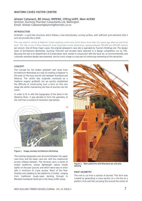
WAITOMO CAVES VISITOR CENTRE Alistair Cattanach, BE (Hons ...
WAITOMO CAVES VISITOR CENTRE Alistair Cattanach, BE (Hons ...
WAITOMO CAVES VISITOR CENTRE Alistair Cattanach, BE (Hons ...

Create successful ePaper yourself
Turn your PDF publications into a flip-book with our unique Google optimized e-Paper software.
<strong>WAITOMO</strong> <strong>CAVES</strong> <strong>VISITOR</strong> <strong>CENTRE</strong><br />
<strong>Alistair</strong> <strong>Cattanach</strong>, <strong>BE</strong> (<strong>Hons</strong>), MIPENZ, CPEng IntPE, Mem ACENZ<br />
Director, Dunning Thornton Consultants Ltd, Wellington<br />
Email: <strong>Alistair</strong>.<strong>Cattanach</strong>@dunningthornton.co.nz<br />
INTRODUCTION<br />
Gridshell = a grid-like structure which follows a two-directionally curving surface, with sufficient grid elements that it<br />
acts structurally like a shell.<br />
per annum. One of three major caves, the original glowworm cave site is operated by Tourism Holdings Ltd. The design<br />
team of Architecture Workshop, Dunning Thornton and eCubed were selected in a design competition run by THL.<br />
Because the site is on Department of Conservation land, owned in conjunction with the local iwi, an environmentally and<br />
culturally sensitive design was essential, and its iconic image is a key part of continuing marketing of this attraction.<br />
CONCEPT<br />
The concept for the timber gridshell roof came from<br />
Architecture Workshop as a way of creating a stopover in<br />
the bush on the busy tourist trail between Auckland and<br />
Rotorua. The centre was originally conceived as a<br />
freeform organic gridshell, but we quickly established<br />
the difficulty of constructing such a form on this very<br />
steep site whilst maintaining the flow of tourists into the<br />
caves.<br />
In order to fit in with the topography of the bend in the<br />
Waitomo River, it was decided to form the geometry of<br />
the roof from a surface of revolution (see below).<br />
Figure 1. Image courtesy Architecture Workshop<br />
The existing topography was terraced between the upper<br />
cave entry and the lower cave exit, with the road/tunnel<br />
access midway between. The terraces carry a series of<br />
timber platforms, whose lightweight nature treads<br />
lightly on the poor ground, and which were easy to erect<br />
with a minimum of crane access. Much of the floor<br />
finishes and cladding to the platforms is timber, ranging<br />
from traditional rough-sawn decking through to<br />
Blackbut hardwood-faced ply in the heavy traffic areas.<br />
Figure 2. Main platforms with Blackbutt ply and pine<br />
decking<br />
ROOF GEOMETRY<br />
The roof is cut from a section of tauroid. This form was<br />
created by generating a cross-section on a rib-line as a<br />
perfect circle and then arraying this around the centre of<br />
NEW ZEALAND TIM<strong>BE</strong>R DESIGN JOURNAL VOL 18· ISSUE 3 7
the tauroid to create the form. Whilst the ribs are<br />
generated from this circle, their form is much more<br />
complex.<br />
and by back-checking in the 3D CAD geometry<br />
(measuring each side of each rib: equal lengths = no<br />
secondary bending).<br />
Figure 3. Image courtesy Architecture Workshop<br />
The orientation of each rib is set to always face the<br />
Figure 4). To do this the rib must curve and twist as it<br />
crosses the roof. A simple way to picture this might be to<br />
imagine laying a ribbon across the curve of a tyre tube.<br />
As the rib takes this form, it not only wants to bend about<br />
its major axis and twist, but also to bend about a<br />
secondary axis. In order to fabricate ribs that were bent<br />
only about one axis (and twisted), we allowed the ribs to<br />
-shape in plan. This removed the<br />
secondary bending. This process required extensive<br />
structural form-finding, which was done by a<br />
mathematical process, a structural modelling process<br />
Figure 4. Multiple grid geometries (lighter and darker grey)<br />
on the same shell surface:<br />
Figure 5.<br />
object.<br />
The S-curve formed by bending and twisting an<br />
The cladding comprises ETFE pillows: inflated cushions<br />
of high-strength plastic, seen recently at the Watercube<br />
at the Beijing Olympics. These cushions could be<br />
patterned to the two-directional curvature of the<br />
gridshell. However, if they were to be broken into<br />
diamonds as in other similar previous projects, their<br />
cladding would be significantly more expensive - the<br />
majority of the cost coming from the aluminium<br />
extrusion seaming and clamping at the perimeter. Lifting<br />
-<br />
-<br />
cushions, the belly of which cleared the timber<br />
structure.<br />
Rib centres were selected to optimise spans for<br />
commercially available thicknesses of ETFE foil at an<br />
average of 4.25m. The line of the cushion edges follow<br />
over the ribs in their own similar S-curve: the edge<br />
extrusions also being bent only about one axis and<br />
twisted.<br />
Figure 6. Roof geometry courtesy Architecture Workshop<br />
8 NEW ZEALAND TIM<strong>BE</strong>R DESIGN JOURNAL VOL 18· ISSUE 3
2-M16X200 COACH SCREWS, SHOP<br />
DRILL SHANK Ø X LENGTH. SITE DRILL<br />
ROOT DIA. TO 220 LONG<br />
4X/ 8MM OUTER<br />
THREADED DIA. 300<br />
LONG SPAX SCREWS<br />
110 40<br />
their perimeter members. With the cushions connected<br />
in a series these forces balance, but still the perimeter<br />
of the overall roof is subject to high (3-8kN/m) pull-in<br />
forces. These are resisted by a complex series of edge<br />
catenaries and tethers as shown in the images below.<br />
3-14g BATTEN<br />
SCREWS, 150 LONG<br />
Figure 7. Typical block detail<br />
90<br />
STRUCTURAL ACTIONS<br />
In the first instance, the timber ribs act as large arches<br />
spanning the 28m across the structure. These arches<br />
are made from two layers of LVL ribs interconnected<br />
with intermittent blocks. By clamping the blocks<br />
between the two layers, Vierendeel action allows<br />
localised loads to be shared out to the greater shell<br />
structure.<br />
Because the arches are arrayed around a circle of<br />
revolution, when wind actions try to rack the structure,<br />
the diagonal nature of the grid causes it to lock up as it<br />
rolls forward, i.e. the arches at the end are skewed to<br />
the arches in the centre, and hence under racking loads<br />
the ends act as diagonal braces.<br />
Because of the unusual geometry, wind actions on the<br />
structure were derived from a wind tunnel test. The two<br />
dominant load cases were maximum uplift from the wind<br />
blowing in the end of the structure, and the forward<br />
racking of the shell from the wind blowing down the hill.<br />
As the structure weighs less than 30kg per square<br />
metre, gravity load cases did not dominate over wind.<br />
Figure 9. Top edge catenaries<br />
The structure needs to allow for any one cushion to<br />
become deflated suddenly, and repaired/replaced. With<br />
the e-plane over 0.5m above the t-plane, the resulting<br />
twisting forces on the intermediate structural members<br />
would usually be immense. To counter this, we<br />
conceived a world-first system where the cushions are<br />
held on a series of flexible poles above the timber<br />
structure. The e-plane is therefore free to move above<br />
the t-plane as unsymmetrical loads are placed upon the<br />
utilising a 20mm pad of neoprene at the fixing point.<br />
Figure 10. Major Edge support<br />
Figure 8. T-plane cables<br />
allowing the two ends of the shell to move towards each<br />
other. Similarly, as the structure eases down when the<br />
wind drops, or under gravity loads, the tips relax<br />
downwards and outwards. To control these tendencies, a<br />
net of cables were included in the t-plane: cables<br />
crossing the diamonds inhibit this scissoring action. The<br />
dominant uplift loads are evident in the greater number<br />
of transverse cables, as shown in the diagram below.<br />
The ETFE cushions resist forces by pulling inwards on<br />
Figure 11. Lower edge catenaries<br />
NEW ZEALAND TIM<strong>BE</strong>R DESIGN JOURNAL VOL 18· ISSUE 3 9
Structurally, this allowed us to limit forces to acting only<br />
along the major axis of the principal members.<br />
FABRICATION<br />
The timber ribs were each fabricated in two layers, so<br />
they could be interwoven to create layers 1-4 as shown<br />
below. Each layer is made from three layers of ex170 x<br />
39mm LVL.<br />
Figure 12. Jig Shop Drawing<br />
together in special jigs to form the curve and twist. The<br />
jig layout, shop-drawn by Dunning Thornton, allowed for<br />
an over-bend and over-twist such that the ribs would<br />
spring back to their ideal shape after the glue had set.<br />
Initial layout in the jigs showed the ribs curving up and<br />
away from the bed. Measurements of this were taken,<br />
and twist tests were made on the prototype to ensure the<br />
correct torsional modulus (G) was being used. Changing<br />
this required re-casting the whole gridshell geometry to<br />
remove the resulting secondary bending stress.<br />
Modification of the jigs to this revised shape indicated a<br />
perfect fit of the timber to the bend and twist required.<br />
Fabrication of the ribs was carried out in winter 2009:<br />
the cold temperatures allowing 4-8 matching ribs to be<br />
glued in the same jig, because the slower glue-setting<br />
time in the cold weather allowed extra time for<br />
manipulation.<br />
All blocks, bolt-holes and other hardware were fitted to<br />
the ribs before H3.1 treatment and the first of four coats<br />
-<br />
34m ribs were formed using high-tensile epoxy rods<br />
shopsite<br />
joint as below.<br />
Figure 13. Rib manufacture<br />
Figures 15/16. Rib splice<br />
Figure 14. Completed half ribs<br />
Each LVL was pre-planed by 1.5mm to remove the wood<br />
compressed during manufacture and allow a fullstrength<br />
glue joint. The three layers were laminated<br />
ERECTION<br />
The gridshell was erected on a birdcage scaffold. The<br />
contact points on the scaffold were difficult to define and<br />
were eventually set as horizontal circular contours<br />
around the structure. The ribs, each weighing<br />
approximately 150kg, were layered over the scaffold<br />
structure with a small long-reach road crane.<br />
10 NEW ZEALAND TIM<strong>BE</strong>R DESIGN JOURNAL VOL 18· ISSUE 3
Figures 19. Entry toilets and cave path<br />
accurately to start and end the rib alignments. After<br />
significant cross-checking the adjustment to the<br />
alignment of each rib, all ribs were positioned well<br />
within tolerance of 40mm in the length (over 28-34m).<br />
Figure 18. Erection photo courtesy Hawkins<br />
Once heights were re-checked, end fixings and the fitting<br />
of node joints and cables could begin. The end fixings<br />
were generally site-drilled 14-gauge self-drilling screws<br />
through the steel bunny ears to achieve the 40mm<br />
tolerance in length. Once all hardware was in place, the<br />
scaffolding was removed and the deflections of the tips<br />
monitored. A tip deflection of 376mm was recorded<br />
against a predicted 377mm, although there was a<br />
subsequent settlement of another 10-15mm after the<br />
structure was oscillated to check the dynamic tip<br />
frequency.<br />
Figure 20. Cave exit path with Visitors centre beyond<br />
The ETFE cushions were then erected in their extrusions<br />
and subsequently inflated. The pull-in force at the<br />
perimeter from this inflation causes the tips of the<br />
gridshell to rise approximately 350mm, countering the<br />
deadload deflection.<br />
Figure 21. Four-way cable node<br />
NEW ZEALAND TIM<strong>BE</strong>R DESIGN JOURNAL VOL 18· ISSUE 3 11
Figure 22. The finished structure<br />
SUMMARY<br />
The structure is unique, and has been interpreted as<br />
symbolising a traditional Maori eel net with its open<br />
weave. The extremely complex geometry pushes the<br />
limits of our three-dimensional modelling tools: there is<br />
a complex procedure to set up a pure cross-section at<br />
any one part of the 3D model. However, this complex<br />
geometry allows an exceptionally light structure, with<br />
timber only 316mm deep at 4.25m centres to span<br />
almost 30m across the roof.<br />
The writer would like to acknowledge Matthew Davies<br />
and Anthony Gardiner from Dunning Thornton for their<br />
tireless dedication in engineering and drawing the roof,<br />
Gareth Alley and Martin Williams for their hard work on<br />
the platforms, Architecture Workshop for their vision<br />
and creativity, Nelsonpine Industries for manufacturing a<br />
non-standard 39mm product for this job, Hunters for<br />
their collaboration and feedback in the timber<br />
fabrication, Vector Foiltech in pushing the boundaries of<br />
ETFE detailing, and Hawkins for their endless hours on<br />
the tools and commitment to accuracy.<br />
12 NEW ZEALAND TIM<strong>BE</strong>R DESIGN JOURNAL VOL 18· ISSUE 3


