BID - TROX
BID - TROX
BID - TROX

You also want an ePaper? Increase the reach of your titles
YUMPU automatically turns print PDFs into web optimized ePapers that Google loves.
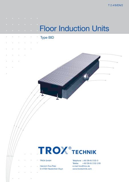
T 2.4/9/EN/2<br />
Floor Induction Units<br />
Type <strong>BID</strong><br />
<strong>TROX</strong> GmbH Telephone +49/28 45/2 02-0<br />
Telefax +49/28 45/202-265<br />
Heinrich-Trox-Platz<br />
e-mail trox@trox.de<br />
D-47504 Neukirchen-Vluyn www.troxtechnik.com
Contents · Description<br />
Description ______________________________________ 2<br />
Construction ·Dimensions _________________________ 3<br />
Materials ________________________________________ 3<br />
Installation _______________________________________ 4<br />
Nomenclature ____________________________________ 5<br />
Performance Overview · Technical Data _____________ 6<br />
Order Details ____________________________________ 8<br />
Function<br />
Supply Air<br />
Linear grille<br />
or roll down<br />
grille<br />
Secondary air<br />
Water<br />
coil<br />
Primary air<br />
Induction nozzles<br />
<strong>TROX</strong> Floor Induction Unit Type <strong>BID</strong> with roll down grille<br />
<strong>TROX</strong> Floor Induction Unit Type <strong>BID</strong><br />
<strong>TROX</strong> Floor Induction Unit Type <strong>BID</strong> with linear grille<br />
Description<br />
<strong>TROX</strong> type <strong>BID</strong> floor induction units are used in air-water based<br />
air conditioning systems. They can help in exploiting the energyeconomy<br />
benefits of load dissipation (heating/cooling) through the<br />
medium of water; even in buildings where rooms have full height<br />
glazing without false ceilings and hence have smaller floor slab to<br />
slab heights.<br />
The external primary air volume flow required for ventilation enters a<br />
spigot into the primary air plenum and is discharged through nozzles.<br />
The secondary air is taken in from the room, passing through coils<br />
where it is heated or cooled, as appropriate. The secondary air<br />
is mixed with the primary air in the <strong>BID</strong>’s mixing zone and then<br />
supplied to the room via a linear grille or roll down grille in the floor<br />
area adjacent to the façade. <strong>BID</strong> diffusers may be used for cooling<br />
or for heating.<br />
When used for heating, <strong>BID</strong> units prevent discomfort caused by<br />
cold air downdraughts at the façade, when used for cooling,<br />
<strong>BID</strong> units minimise the thermal load and thermal radiation from<br />
the façade into the room.<br />
Because of their low height design, type <strong>BID</strong> floor induction units<br />
are particularly suited for use where floor slab to slab heights or<br />
false floor voids are small. The type <strong>BID</strong> unit is thus well suited<br />
2<br />
for use in new buildings, but also in refurbishment projects and<br />
provides maximum architectural freedom, as neither a perimeter<br />
sill nor a suspended ceiling is required.<br />
If connected appropriately, the units can be used both for servicing<br />
individual rooms and for servicing zones with multiple units.<br />
The unit casing is sized so that control valves including actuators<br />
can be built in and thus remain easily accessible. A row of nozzles<br />
is stamped into a plate at the primary air plenum opposite the<br />
supply air spigot. Three different nozzle variants are available,<br />
depending on the required air volume flow rate. The linear grille<br />
or roll down grille can easily be removed for cleaning purposes.<br />
Caution!<br />
The cold water supply temperature must be selected such that<br />
it never falls below room dew point.<br />
Max. pressure:<br />
for 2-pipe and 4-pipe system<br />
6 bar at 90°C<br />
7 bar at 20°C<br />
Other operating pressures available on request!
Constuction · Dimensions<br />
Construction<br />
<strong>TROX</strong> Type <strong>BID</strong> floor induction units consist of a load-bearing<br />
casing with a primary air duct and integral nozzles with various<br />
nozzle free areas for optimum induction at low sound power<br />
levels and pressure losses. The primary air side is connected<br />
via a centrally mounted spigot with a lip seal. The coils may be<br />
designed either for cooling or heating operation as a 2-pipe<br />
system or for cooling and heating operation as a 4-pipe system<br />
with copper pipe connections (Ø 12 x 1 mm), alternatively with<br />
a 1/2” external thread and with optional air venting.<br />
In addition, the units have a mixing chamber and a discharge<br />
area for supply air. The height of the unit may be altered by<br />
means of the adjustable feet.<br />
The grille ledge is suitable for:<br />
• AFN-0-A aluminium linear floor grille<br />
(blades parallel to the façade, grille height 23 mm)<br />
• ARR 20 aluminium roll down grille<br />
(bars perpendicular to the façade, grille height 20 mm)<br />
Combination with other grille options on request.<br />
Materials<br />
Casing and primary air duct are made of galvanised steel sheet.<br />
The coil consists of copper pipes with formed aluminium fins.<br />
The lip seal is made of rubber.<br />
The surfaces are untreated. On request, the casing and/or the<br />
coil can be powder-coated to RAL 9005 (black).<br />
Dimensions in mm<br />
L 1 L N A B<br />
1100...1249 900 895 875<br />
1250...1399 1050 1045 1025<br />
1400...1549 1200 1195 1175<br />
1550...1699 1350 1345 1325<br />
1700...1849 1500 1495 1475<br />
Detail X<br />
(rotated 90° degrees)<br />
Individual unit with perimeter<br />
frame<br />
34<br />
Grille Gitterauflage ledge<br />
B<br />
Linear floor grille type<br />
AFN-0-A or aluminium roll<br />
down grille type ARR20<br />
(order separately)<br />
Coil<br />
Primary air plenum with<br />
integral discharge nozzles<br />
Primary air connection<br />
spigot with lip seal<br />
Casing<br />
Water connection Cu-pipe<br />
Ø 12 x 1 mm, on request<br />
R1/2” external thread<br />
Height-adjustable feet<br />
A<br />
X<br />
191<br />
30<br />
34<br />
View B<br />
<br />
403<br />
361<br />
<br />
ØD*<br />
151<br />
120<br />
*ØD either Ø98 or Ø123<br />
L1<br />
A<br />
45<br />
L2 (LN + 170)<br />
Detail X<br />
(rotated 90° degrees)<br />
Unit for linear assembly<br />
(open-end)<br />
Grille Gitterauflage ledge<br />
View A-A<br />
A<br />
34<br />
10<br />
B<br />
3
Installation<br />
Once the <strong>BID</strong> unit has been lined up with the façade, the<br />
height-adjustable feet can be used to compensate for building<br />
tolerances. Care should be taken to ensure horizontal installation<br />
is achieved. Once this is complete, it is possible to secure or bolt<br />
the unit to the floor using the pre-stamped slots (11 x 30 mm).<br />
The grille or roll down grille selected is then laid on the <strong>BID</strong>’s<br />
grille ledge.<br />
In a continuous grille core installation the core must be suitably<br />
supported if its length is greater than the L 1 dimension selected.<br />
False Floor<br />
Height<br />
adjustment<br />
feet<br />
Floor slab<br />
Pre-stamped slots<br />
(11 x 30 mm) for securing<br />
the unit to the building slab<br />
Single unit installation, e.g. with the AFN-0-A linear grille<br />
Air entry spigot<br />
Primary air plenum<br />
Grille<br />
L1 + 1*<br />
Continuous installation, e.g. with the ARR 20 roll down grille<br />
Air entry spigot<br />
Primary air plenum<br />
Grille<br />
Supports<br />
(supplied by others)<br />
405* 405*<br />
* Floor opening required<br />
4
Nomenclature<br />
1.5 1,5 m<br />
t WRK WK<br />
t WRH ‡ WH<br />
t WVH WH<br />
t WVK ‡ WK<br />
Secondary air<br />
Primary air<br />
‡ Pr<br />
Pr<br />
t Pr<br />
ƒL<br />
∆t L<br />
0.10 0,10 m<br />
Nomenclature<br />
∆t L<br />
∆t Pr<br />
∆t W<br />
∆t RWV<br />
∆p t<br />
∆p W<br />
t R<br />
t AN<br />
t WVK<br />
t WRK<br />
t WVH<br />
t WRH<br />
t Pr<br />
F W<br />
WH<br />
WK<br />
ges<br />
in K: Temp. diff. between room air t R and core t L<br />
in K: Temp. diff. between room air and primary air<br />
in K: Temp. diff. between water flow and return<br />
in K: Temp. diff. between room air and water flow temperature<br />
in Pa: Primary air pressure drop<br />
in kPa: Water pressure drop<br />
in °C: Room temperature<br />
in °C: Induced secondary air temperature<br />
in °C: Water flow temperature – cooling<br />
in °C: Water return temperature – cooling<br />
in °C: Water flow temperature – heating<br />
in °C: Water return temperature – heating<br />
in °C: Primary air temperature<br />
: Correction factor water volume flow rate<br />
in W: Water heating capacity<br />
in W: Water cooling capacity<br />
in W: Total cooling/heating capacity Pr + S<br />
Pr in W: Primary air cooling/heating capacity<br />
S in W: Secondary air cooling/heating capacity<br />
(for cooling S = WK /for heating S = WH )<br />
HK in W: Convective heating capacity<br />
‡ WK in l/h: Water volume flow rate – cooling<br />
‡ WH in l/h: Water volume flow rate – heating<br />
‡ Pr in l/s: Primary air volume flow rate<br />
ƒ L in m/s: Max. time average air velocity<br />
L WA in dB(A): A-weighted sound power level<br />
L N in mm: Nominal length<br />
in mm: Total length of casing<br />
L 1<br />
5
Performance Overview · Technical Data<br />
with 2-pipe / 4-pipe system<br />
Reference values cooling<br />
t R = 26°C<br />
t AN = 24.5°C<br />
F W = 1.0<br />
t WVK = t Pr = 16°C<br />
‡ WK = 110 l/h<br />
∆t Pr = t Pr – t R = –10 K<br />
= t WVK – t R = –10 K<br />
∆t RWV<br />
Reference values heating<br />
t R = t AN = t Pr = 22°C<br />
F W = 1.0<br />
t WVH = 50°C<br />
‡ WH = 50 l/h<br />
∆t RWV = t WVH – t R = 28 K<br />
Room height: 3 m<br />
Connecting spigot Cooling Heating Heating<br />
Ø98 Ø123 2- and 4-pipe system 2-pipe system 4-pipe system<br />
L N Nozzle V . Pr L WA L WA ∆P t v - L ∆t L Q . Pr Q . S Q . ges ∆t W ∆P W Q . S = Q . ges ∆t W ∆P W Q . S = Q . ges ∆t W ∆P W<br />
type (air) (water) (water) (water) (water) (water) (water)<br />
l/s m 3 /h dB(A) dB(A) Pa m/s K Watt Watt Watt K kPa Watt K kPa Watt K kPa<br />
4 14
Technical Data<br />
Convective heating capacity, related to water flow only<br />
(without primary air)<br />
∆t RWV<br />
in K<br />
L N in mm<br />
900 1050 1200 1350 1500<br />
Q . HK in W<br />
10 84 98 112 126 140<br />
15 114 133 152 172 191<br />
20 145 170 194 218 242<br />
25 177 207 236 266 295<br />
30 210 245 280 314 349<br />
35 242 283 323 364 404<br />
40 276 322 368 414 459<br />
45 309 361 412 464 515<br />
50 343 400 458 515 572<br />
Diff. between flow and return water temp. ∆t W in K<br />
17<br />
16 l/h 30 50 l/h 60 70 80 90 100 110<br />
15<br />
14<br />
13<br />
12<br />
11<br />
160<br />
10<br />
9<br />
8<br />
200<br />
7<br />
250<br />
6<br />
5<br />
4<br />
3<br />
2<br />
Water volume flow rate ‡ WK / ‡ WH in l/h<br />
1<br />
0<br />
200 400 600 800 1000 1200 1400 1600 1800 2000 2200<br />
Water-side thermal capacity WK / WH in W<br />
Water pressure drop ∆p W in kPa<br />
20<br />
18<br />
16<br />
14<br />
12<br />
10<br />
2- and 4-pipe<br />
system<br />
Cooling<br />
1500<br />
1500<br />
1200<br />
1200<br />
900<br />
900<br />
8<br />
2-pipe<br />
system<br />
6<br />
Heating 1500<br />
1200<br />
4<br />
900<br />
L N<br />
2<br />
4-pipe<br />
system<br />
0<br />
Heating<br />
40 60 80 100 120 140 160 180 200 220 240 260<br />
Water volume flow rate ‡ WK / ‡ WH in l/h<br />
Correction factors (F W ) water volume flow rate<br />
Cooling<br />
‡ WK in l/h<br />
50 60 70 80 90 100 110 120 140 160 200 250<br />
0.86 0.89 0.92 0.94 0.96 0.98 1.00 1.02 1.04 1.06 1.08 1.09<br />
Heating<br />
‡ WH in l/h<br />
30 40 50 60 70 80 90 100 110 120 140 160<br />
0.92 0.97 1.00 1.03 1.07 1.09 1.12 1.14 1.16 1.19 1.21 1.23<br />
See also our selection programme for air-water systems on the internet at www.trox.de<br />
7
Order Details<br />
Specification Text<br />
Modular floor induction units for air-water air conditioning<br />
systems, in 5 nominal sizes, for ventilating rooms requiring<br />
high levels of comfort, for load dissipation (heating/cooling)<br />
at the façade using water as the medium, for installation in<br />
false floors and cavity flooring.<br />
Comprising: load bearing casing with installation space for<br />
the incorporation of control valves and actuators, side fixed<br />
brackets with height-adjustable feet and slotted holes for<br />
securing to the structure, flange-mounted, interchangeable<br />
primary air duct with integral, non-flammable induction<br />
nozzles and primary air duct spigot with lip seal, three nozzle<br />
variants with varying free cross-sections, circular, deburred<br />
stamped nozzles with a projection height of 2 – 4 mm<br />
depending on the nozzle variant, optimised for high induction<br />
performance at minimum sound power levels and pressure<br />
losses, for adapting to room layout changes nozzles can be<br />
individually closed with plugs, easy-to-clean coils complying<br />
with VDI 6022, optional as a 2-pipe version for heating or<br />
cooling, and as a 4-pipe version for heating and cooling,<br />
copper 12 x 1 mm water connections with the option of right<br />
or left hand, optional with bleed valves and/or pipe connections<br />
with 1/2” external thread, a grille ledge for a linear grille or<br />
roll down grille.<br />
Materials<br />
Casing and primary air duct of galvanised sheet steel, coils<br />
with copper pipes and pressed aluminium fins, untreated<br />
surface, rubber lip seal.<br />
Casing option powder-coated to RAL 9005 (black) and/or<br />
coils black, RAL 9005.<br />
Order Code<br />
These codes do not need to be completed for standard products<br />
<strong>BID</strong> - 2 - M - R - E / 1197 x 900 x 98 / 0 / K00 / P1 / RAL 9005 / G3<br />
Water coil<br />
Two-pipe -2<br />
Four-pipe -4<br />
Nozzle options<br />
M<br />
G<br />
U<br />
IEOEP<br />
IEOEP<br />
1100...1249 x 900<br />
1250 ... 1399 x 1050<br />
1400 ... 1549 x 1200<br />
1550 ... 1699 x 1350<br />
1700 ... 1849 x 1500<br />
L 1 x L 1) N<br />
(mm)<br />
Not used<br />
98<br />
123<br />
ØD 2)<br />
(mm)<br />
State colour<br />
0 Coil untreated<br />
G3 Coil RAL 9005,<br />
black<br />
Design changes reserved · All rights reserved © <strong>TROX</strong> GmbH (5/2008)<br />
Casing arrangement<br />
Right hand R<br />
Left hand L<br />
IEOEP<br />
1) Total length x nominal length<br />
2) Diameter of connecting spigot<br />
on request Ø98 or Ø123<br />
Order example<br />
Make: <strong>TROX</strong><br />
Type: <strong>BID</strong> - 2 - M - R - E / 1197 x 900 x 98 / K00 / P1 / G3<br />
IEOEP<br />
E<br />
B<br />
Individual unit<br />
Linear assembly<br />
IEOEP<br />
0 Standard galvanised<br />
finish<br />
P1 Casing powder-coated<br />
RAL 9005, black<br />
0 Standard<br />
Connections Cu-pipe Ø 12 x 1 mm<br />
E00 Air vent valve for heating and/or<br />
cooling circuit<br />
A00 Connections R1/2” external thread<br />
K00 Combination of E and A<br />
Please order separately linear grille or roll down grille:<br />
Aluminium roll down grille (ARR20)<br />
see product information leaflet PI/T1.1/2/EN/...<br />
Aluminium linear grille (AFN-0-A)<br />
see product information leaflet PI/T1.1/3/EN/...<br />
IEOEP<br />
8