Profiled Sheeting Design Guide: Part 3 - Barbour Product Search
Profiled Sheeting Design Guide: Part 3 - Barbour Product Search
Profiled Sheeting Design Guide: Part 3 - Barbour Product Search

Create successful ePaper yourself
Turn your PDF publications into a flip-book with our unique Google optimized e-Paper software.
For more information on Marley Eternit visit www.barbourproductsearch.info<br />
cranked<br />
single skin<br />
vertical cladding<br />
detailing<br />
ventilation<br />
40 <strong>Profiled</strong> design detailing sheeting design guide
For more information on Marley Eternit visit www.barbourproductsearch.info<br />
crown<br />
insulated systems<br />
eaves closure<br />
<strong>Design</strong> detailing<br />
42-45 Ridges<br />
46-49 Eaves<br />
50-51 Bargeboards<br />
52-53 Translucent sheets<br />
56-59 Vertical cladding<br />
60-61 Miscellaneous fittings<br />
62-65 Ventilation<br />
66-71 Rainwater goods<br />
54-55 Movement joints<br />
<strong>Profiled</strong> sheeting design detailing guide 41
For more information on Marley Eternit visit www.barbourproductsearch.info<br />
Ridges<br />
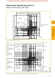
Cranked crown ridges<br />
Cranked crown ridge pieces are one-piece<br />
fittings for closing off Profile 6 sheeting at the<br />
crown of a roof.<br />
They are made with an accurate profile, giving<br />
a precise fit and are manufactured in pitches<br />
of 5° to 22 1 /2° in 2 1 /2° increments. These sheet<br />
pitches can be used with any roof pitch from<br />
5° to 23 1 /4°. (See table opposite.)<br />
Available girths are 750 and 900mm.<br />
Before laying cranked crown ridge pieces,<br />
it is important to ensure that the sheets on<br />
both roof slopes are aligned correctly.<br />
The ridge purlins should be positioned so that<br />
the fixings are located not less than 100mm<br />
from the ends of the cranked crown ridge<br />
pieces. (See Figs.1 and 2).<br />
To form a non-fragile ridge detail, the cranked<br />
crown should be lapped by 300mm onto the<br />
sheeting on each side of the ridge.<br />
Where cranked crown ridge pieces overlap,<br />
both the cranked crowns and the lower<br />
sheets are to be mitred on each roof slope.<br />
100mm min.<br />
Profile 6<br />
sheet<br />
300mm<br />
Standard 300mm<br />
radius<br />
750 or 900mm girth to underside of sheet<br />
Profile 6<br />
sheet<br />
Fig.1 – Cranked crown fixings<br />
Fig.3 – Typical built up system<br />
100mm min.<br />
Profile 6<br />
sheet<br />
300mm<br />
Standard 300mm<br />
radius<br />
750mm girth to underside of sheet<br />
Profile 6<br />
sheet<br />
Fig.2 – Ventilating cranked crown fixings<br />
42 <strong>Profiled</strong> sheeting design guide
For more information on Marley Eternit visit www.barbourproductsearch.info<br />
General methods of<br />
application<br />
Figs 1 and 2 are typical details which, using the<br />
same principles, can be applied to situations other<br />
than those illustrated.<br />
Ventilating cranked crown ridge pieces<br />
These match in with cranked crown ridge pieces<br />
and give ventilation whilst providing reasonable<br />
weatherproofing.<br />
They may be used in continuous runs, or<br />
intermittently with plain cranked crown ridge pieces.<br />
If used in continuous runs, provide one standard<br />
cranked crown ridge piece at each end of the<br />
building. When fitted as recommended here, each<br />
ventilating cranked crown provides a free air area<br />
of 68,360mm 2 .<br />
Purlin position<br />
Note that the purlins can be positioned up slope<br />
from the position shown in Figs. 1 and 2.<br />
Cranked crown Roof pitches<br />
sheet pitch from to<br />
5° 5° 5 3 /4°<br />
7 1 /2° 6° 8 1 /4°<br />
10° 8 1 /2° 10 3 /4°<br />
12 1 /2° 11° 13 1 /4°<br />
15° 13 1 /2° 15 3 /4°<br />
17 1 /2° 16° 18 1 /4°<br />
20° 18 1 /2° 20 3 /4°<br />
22 1 /2° 21° 23 1 /4°<br />
Note<br />
The cranked crown ridge pieces, if fixed in the position<br />
shown in Figs.1 and 2, will meet the non-fragility<br />
requirements of HSG 33.<br />
When 750mm girth cranked crown and cranked vents (Fig.2)<br />
are used on roof pitches of 15° to 22 1 /2°, the 300mm<br />
overlap encroaches onto the curved part of the cranked<br />
crown ridge. In order to avoid damage, an 8mm butyl strip<br />
should be used as a spacer between the top of the sheet<br />
and the underside of the cranked crown unit.<br />
Built up systems<br />
Please contact Marley Eternit for further details.<br />
<strong>Profiled</strong> sheeting design guide 43
For more information on Marley Eternit visit www.barbourproductsearch.info<br />
Ridges<br />
Two-piece ridges<br />
The following ridges will accommodate a range of roof<br />
pitches because of their adjustable two-piece construction.<br />
Each ridge gives a net covering width of 1016mm, to match<br />
the Profile 6 sheeting.<br />
All ridges should be fixed directly to the purlins, through the<br />
crowns of the corrugations of the roof sheeting.<br />
Single skin roofs<br />
Two-piece close fitting ridge (Fig.1)<br />
It is essential that the two sides of the roof sheeting<br />
be aligned correctly before fixing of the close fitting<br />
ridge is attempted. (For details of laps of ridge<br />
pieces, see the positioning drawings opposite.)<br />
For dimensions see Notes below.<br />
Two-piece plain wing ridge (Fig.2)<br />
This ridge gives a neat finish to a roof apex. Easily<br />
fixed, it provides adequate weather protection, but<br />
does not close off the corrugations of the roof<br />
sheeting, thus allowing a measure of ventilation.<br />
Two-piece ventilating ridge (Fig.3)<br />
This matches in with the close fitting ridge, but<br />
gives ventilation whilst providing reasonable<br />
weatherproofing. Positioning and fixing are as<br />
for the close fitting ridge.<br />
When used in continuous runs, one pair of close<br />
fitting ridges should be laid at each end of the run<br />
to provide a neat finish at each verge.<br />
Northlight ridge<br />
This has one large roll close fitting ridge and one<br />
small roll plain wing ridge.<br />
Notes<br />
For Figs.1-4, the gap between the sheets at the apex should<br />
not be greater than 150mm.<br />
When fitted as shown above, the three ridge types will meet<br />
the non-fragile requirements of HSG 33.<br />
When fitted in accordance with Marley Eternit<br />
recommendations, the free air area provided by these units<br />
are as follows.<br />
• Two piece ventilating ridge: 33,670mm 2 per pair<br />
• Two piece plain wing ridge: 46,470mm 2 per pair<br />
Built up systems<br />
Please contact Marley Eternit for further details.<br />
44 <strong>Profiled</strong> sheeting design guide
For more information on Marley Eternit visit www.barbourproductsearch.info<br />
100<br />
mm<br />
276mm<br />
75mm<br />
100<br />
mm<br />
100<br />
mm<br />
300mm<br />
75mm<br />
100<br />
mm<br />
100<br />
mm<br />
276mm<br />
66mm<br />
100<br />
mm<br />
120mm<br />
100mm<br />
min.<br />
100mm<br />
min.<br />
125mm<br />
min.<br />
125mm<br />
min.<br />
100mm<br />
min.<br />
100mm<br />
min.<br />
Profile 6 sheet<br />
Profile 6 sheet<br />
Profile 6 sheet<br />
Profile 6 sheet<br />
Profile 6 sheet<br />
Profile 6 sheet<br />
Fig.1 – Two-piece close fitting ridge<br />
Fig.2 – Two-piece plain wing ridge<br />
Fig.3 – Two-piece ventilating ridge<br />
Fig.5 – Position of two piece ridges<br />
<strong>Sheeting</strong> left to right, small roll of ridge<br />
<strong>Sheeting</strong> right to left, large roll of ridge<br />
Example 1<br />
<strong>Sheeting</strong> right to left, small roll of ridge<br />
<strong>Sheeting</strong> left to right, large roll of ridge<br />
Fig.4 – Typical built up system<br />
Example 2<br />
<strong>Profiled</strong> sheeting design guide 45
For more information on Marley Eternit visit www.barbourproductsearch.info<br />
Eaves<br />
Eaves bend sheets<br />
Eaves bend sheets provide a neat, simply detailed<br />
transition from profiled roof sheeting to vertical cladding<br />
of the same profile.<br />
46 <strong>Profiled</strong> sheeting design guide
For more information on Marley Eternit visit www.barbourproductsearch.info<br />
For single skin roofs<br />
They are supplied in a standard girth of 1525mm,<br />
and are available to suit roof pitches of 5° to 22 1 /2°<br />
in 2 1 /2° increments.<br />
The positioning of the purlins and rails is critical<br />
to achieve a non-fragile eaves construction.<br />
Please contact us for further information.<br />
Fixing eaves bend sheets<br />
Eaves bend sheets should be installed in sequence<br />
in a vertical tier of sheets from the base of the<br />
cladding to the apex of the roof.<br />
They should be mitred as detailed for the roof<br />
sheeting, see page 18.<br />
Eaves bend sheets should only be fixed to the<br />
lowest purlin of the roof slope and to the top rail<br />
of the vertical cladding.<br />
Note<br />
For advice on recommended methods of fixing Profile 6<br />
sheets on vertical cladding, refer to pages 56-57.<br />
<strong>Profiled</strong> sheet<br />
Eaves bend sheet<br />
standard radius 300<br />
Eaves bend sheet fixed through vertical<br />
sheeting to top rail of wall cladding.<br />
See note on fixing eaves bend sheets<br />
Fig.1 – Eaves bend sheet fixings
For more information on Marley Eternit visit www.barbourproductsearch.info<br />
Eaves<br />
Eaves closure pieces<br />
Eaves closure pieces are designed to close the corrugation/insulation<br />
spaces at the eaves and form<br />
a downturn into the gutter, ensuring a barrier against<br />
wind-driven rain. The units are universal, i.e. not handed.<br />
<strong>Profiled</strong> sheet<br />
Eaves filler<br />
Roof sheet<br />
150<br />
Eaves closure<br />
Valley gutter<br />
Fascia board<br />
Fig.1 – valley gutter fixings<br />
Fig.2 – Eaves filler pieces<br />
Back<br />
Fig.3 – Typical built up system<br />
Fig.4 – Eaves closure<br />
48 <strong>Profiled</strong> sheeting design guide
For more information on Marley Eternit visit www.barbourproductsearch.info<br />
Single skin roofs<br />
Positioning eaves closure pieces<br />
Before sheeting commences, ensure that the purlin<br />
at the eaves is correctly positioned to give the<br />
required overhang of the sheeting over the gutter.<br />
The maximum unsupported overhang for Profile 6<br />
sheets is 350mm.<br />
Each eaves closure piece is fixed at two points,<br />
either with the main roof fixings directly to the<br />
lowest purlin or with secondary fasteners such<br />
as Laplox, or similar, to the roof sheets.<br />
When fixing eaves closure pieces, consideration<br />
must be given to the position of the back (see<br />
Fig.4) in relation to the gutter. Position the back as<br />
tightly as possible against the gutter or vertical<br />
cladding to reduce draughts and restrict driving<br />
rain, sleet or snow from penetrating the interior of<br />
the roof.<br />
When ventilation into the roof void is required, a<br />
slight gap can be allowed between the back of the<br />
closer and the vertical cladding.<br />
For single skin applications, closers with 65mm or<br />
100mm back are typically used.<br />
Closers with 150mm and 250mm back are also<br />
available for insulated constructions (see Fig.3).<br />
Valley gutter detail with eaves closure<br />
pieces (Fig. 1)<br />
Eaves closure pieces can be used at a valley<br />
gutter. Ideally, they should be fixed with the main<br />
sheet fixings, but they can also be stitched to the<br />
sheets with secondary fasteners.<br />
Eaves filler pieces (Fig. 2)<br />
These units close the corrugations of the roof<br />
sheeting at the eaves and provide a continuous flat<br />
soffit to the underside of the roof sheeting for close<br />
sealing to the top of a wall or the edge of a gutter.<br />
Eaves filler pieces are universal, and should either<br />
be screwed directly to the purlins or the wall plates<br />
along with the roof sheeting, or stitched to the roof<br />
sheets with the appropriate fixings.<br />
Built up systems<br />
Please contact Marley Eternit for further details.<br />
<strong>Profiled</strong> sheeting design guide 49
For more information on Marley Eternit visit www.barbourproductsearch.info<br />
Bargeboards<br />
The range of profiled sheeting bargeboards provides a choice<br />
of weatherproof finishes to the verges of a building. With each<br />
bargeboard, one leg extends across the roof sheeting while<br />
the other covers the top of the masonry wall or vertical<br />
cladding.<br />
Bargeboards are fixed with topfix fasteners to the purlins<br />
and also screwed to the wall or vertical cladding.<br />
Eaves bend bargeboards are available to suit eaves bend<br />
sheets in 1575mm girth and are available for roof pitches<br />
from 5° to 22 1 /2° in 2 1 /2° increments.<br />
Handing of bargeboards<br />
Vergeline bargeboards and any eaves bend<br />
bargeboards are handed, as viewed from the<br />
gable end. Roll top and plain wing bargeboards are<br />
universal, as are all cranked crown bargeboards.<br />
Any reduction in length should be made from the<br />
non-socketed end.<br />
Fixing bargeboards<br />
Bargeboards should be positioned so that their<br />
lap is directly below the end lap of the sheeting,<br />
with the top of the under-lapping bargeboard close<br />
to the tail of the sheet in the course above. When<br />
the gable is brick or block, position the bargeboard<br />
25mm clear of the face of the wall. Fix both legs of<br />
the bargeboard to the roof and the wall at all purlin<br />
positions. Intermediate fixings should be introduced<br />
as necessary to ensure that the bargeboard fixings<br />
are at 750mm maximum centres. (Figs.1-3).<br />
Built up systems<br />
Please contact Marley Eternit for further details.<br />
Note<br />
As the verge is the part of the roof that is often the most<br />
vulnerable to wind damage, more fastenings are required<br />
there to ensure that bargeboards in general and the ends<br />
of the bargeboards in particular are always securely fixed.<br />
Roof sheet<br />
200 or 300<br />
25<br />
Roof sheet<br />
300<br />
Roof sheet<br />
200 or 300<br />
200<br />
or 300<br />
310<br />
200<br />
or 300<br />
Fig.1 – Roll top bargeboard<br />
Fig. 2 – Vergeline bargeboard<br />
Fig.3 – External plain wing bargeboard<br />
50 <strong>Profiled</strong> sheeting design guide
For more information on Marley Eternit visit www.barbourproductsearch.info<br />
Roll top bargeboards<br />
200 x 200mm Straight lengths 1800, 2440, 3000mm<br />
300 x 300mm Straight lengths 1800, 2440, 3000mm<br />
200 x 200mm Cranked 1300, 2200mm girths<br />
300 x 300mm 5° - 22 1 /2° in 2 1 /2° increments<br />
200 x 200mm Eaves bends 1575mm girth<br />
5° - 22 1 /2° in 2 1 /2° increments<br />
Roll top bargeboards (Farmscape)<br />
200 x 200mm Straight lengths 1525, 2440, 3000mm<br />
200 x 200mm Cranked 1050mm girth<br />
10°, 12 1 /2°, 15°, 17 1 /2° increments<br />
Vergeline bargeboards (handed)<br />
300 x 310mm Straight lengths 1800, 2400, 3000mm<br />
300 x 310mm Cranked crowns 1300mm girth<br />
5° - 22 1 /2° in 2 1 /2° increments<br />
(Farmscape 10°, 12 1 /2°, 15°, 17 1 /2°)<br />
Plain wing bargeboards<br />
200 x 200mm Straight lengths 1800, 2440, 3000mm<br />
300 x 300mm Straight lengths 1800, 2440, 3000mm<br />
200 x 200mm Cranked 1300, 2200mm<br />
300 x 300mm Cranked 1300, 2200mm<br />
5° - 22 1 /2° in 2 1 /2° increments<br />
Fig.4 – Typical built up system<br />
<strong>Profiled</strong> sheeting design guide 51
For more information on Marley Eternit visit www.barbourproductsearch.info<br />
Translucent sheets<br />
Generally, rooflights formed of translucent sheeting, whether<br />
site or factory assembled, are installed in the same manner as<br />
fibre cement sheeting. The main difference is that translucent<br />
material is thinner and therefore requires more frequent fixing.<br />
Translucent sheet rooflights are laid unmitred, and since the<br />
problem of compound layers at end lap situations does not<br />
occur, adjacent fibre cement sheets are also left unmitred<br />
at these junctions.<br />
Single skin rooflights<br />
Marley Eternit can supply a range of translucent<br />
sheets to meet the requirements of ACR (M) 001:<br />
2005 and with various fire ratings.<br />
The translucent sheets should be supported at<br />
each purlin position by profiled fillers, fibre cement<br />
sheets, or fibre cement closure pieces (Fig.1).<br />
End laps and side laps should be sealed with<br />
10mm diameter extruded mastic sealant.<br />
Self-sealing fasteners with a synthetic rubber shank<br />
or seam bolts and washers with wide bearings are<br />
recommended for side stitching. Self-tapping<br />
screws and blind rivets should not be used for<br />
stitching side laps.<br />
Translucent sheets should be fixed through every<br />
corrugation (not including the side laps) to the<br />
purlins (Fig.2). The same fixings are used as for<br />
fibre cement sheeting, but the holes for GRP<br />
translucent sheets should be 2mm oversize, and<br />
for polycarbonate sheets 6mm oversize (for sheet<br />
lengths up to 2m, otherwise 9mm oversize).<br />
All recommendations of the specialist translucent<br />
sheeting supplier should be carefully observed.<br />
The fixing recommendations will vary depending<br />
on the type, grade and supplier of the material<br />
being used.<br />
Double skin rooflights<br />
Double skin rooflights can be either Factory<br />
Assembled Insulating Rooflights (FAIRs), or siteassembled.<br />
For full details of Factory Assembled<br />
Insulating Rooflights, consult the manufacturers.<br />
Site-assembled rooflights<br />
Site-assembled rooflights are more common<br />
because they are more economical to install.<br />
In double skin constructions, all four edges of a<br />
translucent sheet or area should have rigid foam<br />
supports/closures provided at the laps with the<br />
fibre cement sheets. Support pieces should also<br />
be installed where translucent sheets pass over<br />
intermediate purlins.<br />
Laylights<br />
A double skinned flat box, made to the same<br />
dimensions as the rigid insulation, can be obtained.<br />
The joints between the double skinned box and the<br />
insulation board are sealed with foil backed acrylic<br />
adhesive tape 50mm wide to create a vapour proof<br />
check within the building. Installation of the<br />
weathering sheets above this, in effect, creates a<br />
triple skin.<br />
Factory Assembled Insulating Rooflights<br />
(FAIRs) (Fig. 4)<br />
FAIRs are delivered to site ready to install.<br />
Packing may be needed at intermediate purlins,<br />
if the air gap in the FAIR is not as deep as the<br />
insulation. Always follow the manufacturer’s fixing<br />
recommendations.<br />
52 <strong>Profiled</strong> sheeting design guide
For more information on Marley Eternit visit www.barbourproductsearch.info<br />
Translucent sheet<br />
100 50<br />
Roof sheet<br />
10mm butyl strip<br />
Seam stitching points<br />
Roof sheet<br />
100 50<br />
Sealing strip<br />
Roof<br />
sheet<br />
Translucent<br />
sheet<br />
Roof<br />
sheet<br />
Sealing strip<br />
End closure 65mm<br />
back. Used at head<br />
of translucent<br />
sheets for support<br />
10mm butyl strip<br />
Fig.1 – End lap details for translucent sheet rooflights<br />
Fig.2 – Side lap detail for translucent sheet rooflights<br />
Fig.3 – Typical built up system<br />
Fig.4 – FAIR system<br />
<strong>Profiled</strong> sheeting design guide 53
For more information on Marley Eternit visit www.barbourproductsearch.info<br />
Movement joints<br />
Components for single and double skin roofs:<br />
• Straight movement joint pieces<br />
(lengths: 1800, 2440, 3000mm)<br />
• Cranked crown movement joint pieces<br />
(length: 1300mm)<br />
• Movement joint stop ends<br />
• Movement joint two-piece ridge caps<br />
(see illustration bottom right)<br />
Movement<br />
joint<br />
311<br />
Movement joint<br />
stop end – down leg<br />
cut to suit site detail<br />
Lap of<br />
movement<br />
joint<br />
Lap of roof sheet<br />
Straight<br />
movement joint<br />
25 to 30mm<br />
Purlin<br />
Crown sheet<br />
Fig.1 – Movement joints and elevation<br />
Fig.2 – Movement joint side elevations<br />
2 piece movement<br />
joint ridge cap<br />
Straight<br />
movement joint<br />
Lap of ridge<br />
and roof sheet<br />
Lap of<br />
movement joint<br />
Adjustable<br />
close fitting ridge<br />
Fig.3 – Movement joint ridge cap<br />
Fig.4 – Typical built up system<br />
54 <strong>Profiled</strong> sheeting design guide
For more information on Marley Eternit visit www.barbourproductsearch.info<br />
Forming movement joints<br />
Where the movement joint is to be formed, each<br />
sheet is cut through the valley at the centre of the<br />
sheet, and the resulting pair of half sheets spaced<br />
25 to 30mm apart.<br />
The movement joint should be laid with the top end<br />
butting up to the bottom edge of the next sheet<br />
upslope allowing a min. 150mm lap.<br />
The movement joint pieces are fixed to the purlins<br />
using the same method of fixing as the roof sheets,<br />
with one fixing in the centre of the movement joint<br />
at each purlin run. This fixing should pass through<br />
the gap between the two half sheets and must not<br />
be overtightened. (Figs 1 and 2).<br />
Movement joint cranked<br />
crown caps<br />
Cranked crown caps are available in a range to<br />
suit the standard Profile 6 cranked crown ridge<br />
pieces. When laying cranked crown ridge pieces,<br />
form a 25 to 30mm movement gap as detailed<br />
opposite and cover it with the crown cap, screwing<br />
this directly to the ridge purlins. Note that when<br />
laying the straight movement joint, the top end<br />
should butt up to the overlap of the cranked crown<br />
ridge piece. The crown cap, being longer than the<br />
crown ridge piece will then correctly overlap the<br />
straight movement joint.<br />
Movement joint stop ends<br />
Intended to close the open end of a movement<br />
joint, stop ends are made to fit over the sheeting<br />
and into a straight movement joint. They should be<br />
fixed by bolting to the movement joint.<br />
Movement joint ridge caps<br />
These are used in the same way as movement<br />
joint cranked crown caps, but designed to fit<br />
two-piece close fitting ridges (Fig.3).<br />
Applications<br />
Movement joints are intended for use in long,<br />
continuous stretches of roofing or vertical sheeting,<br />
to accommodate thermal and other movements.<br />
BS 8219 recommends that movement joints<br />
be included in stretches of roofing and vertical<br />
sheeting on buildings exceeding 45 metres<br />
in length.<br />
They should also be designed to coincide with<br />
any structural or movement joints provided in the<br />
building, in which case, there should always be a<br />
movement joint through the complete system.<br />
For buildings in which the temperature or humidity<br />
is higher than normal, or which are subjected to<br />
sudden changes in temperature, the movement<br />
joints may be required at closer centres than<br />
indicated. Contact the Marley Eternit Technical<br />
Department for further advice.<br />
Movement joints for single<br />
and built up roofs<br />
Recommended spacings<br />
Length of<br />
building<br />
0-45m 0<br />
45-75m 1<br />
75-105m 2<br />
Number of<br />
movement joints<br />
Plus one extra movement joint for every additional 30 m<br />
For built up roofs<br />
Fig.4<br />
Movement joints generally only need to be formed<br />
in the Profile 6 weathering sheets as a provision for<br />
movement and are not normally required in the<br />
lining panel or insulated board.<br />
<strong>Profiled</strong> sheeting design guide 55
For more information on Marley Eternit visit www.barbourproductsearch.info<br />
Vertical cladding<br />
<strong>Profiled</strong> sheeting can be used in a wide range of vertical details for<br />
agricultural, industrial and residential applications.<br />
Top Fix Systems<br />
When fixing Profile 6 using topfix fasteners on a<br />
vertical application, some provision must be made<br />
to support the weight of the sheets, otherwise the<br />
sheets will sag down from their intended position<br />
and both the fasteners and the fibre cement<br />
will be overstressed.<br />
The base of each sheet should be supported on<br />
two support clips which hook over the sheeting rail.<br />
The support clips should be positioned in the valley<br />
corrugations adjacent to the fixing position.<br />
Valley fasteners<br />
An alternative solution, which doesn’t require the<br />
support clips, is to fix the sheets in the valley<br />
corrugations. The sheets should be predrilled with<br />
a 2mm oversize hole. The SFS fasteners suitable<br />
for this application are as follows:<br />
• Hot rolled rails: SD12 – T15 – 5.5 x 70 together<br />
with BAZ washers<br />
• Cold rolled rails: SD3 – T15 – 5.5 x 60 together<br />
with BAZ washers<br />
• Timber rails: TDC – T – T16 – 6.3 x 76 together<br />
with BAZ washer (drill a 4mm pilot hole in the<br />
timber rail).<br />
The fixing methods described above can be used<br />
on single skin applications.<br />
Double skin applications<br />
Please contact the Marley Eternit Technical<br />
Department for further details.<br />
Clip fabricated from<br />
13 x 3.2mm steel bar<br />
and galvanized<br />
SFS fixing on<br />
crest of corrugation<br />
2 no. per sheet<br />
Support clip used<br />
on trough of<br />
corrugation<br />
2 no. per sheet<br />
Fig.1 – Single skin vertical cladding<br />
Clip fabricated from<br />
13 x 3.2mm steel bar<br />
and galvanized<br />
Ashgrid AG40 support<br />
system fixed in<br />
accordance with<br />
Ash & Lacy<br />
recommendations<br />
SFS fixing on<br />
crest of corrugation<br />
2 no. per sheet<br />
Liner sheet<br />
Support clip used<br />
on trough of<br />
corrugation<br />
2 no. per sheet<br />
Fig.2 –Typical Double skin vertical cladding<br />
56 <strong>Profiled</strong> sheeting design guide
For more information on Marley Eternit visit www.barbourproductsearch.info<br />
200<br />
311<br />
200<br />
Movement joint<br />
Fig.3 - Internal corner section<br />
Fig.4 - Vertical movement joint<br />
<strong>Sheeting</strong> rail<br />
Fixing position<br />
for secondary fastener<br />
200<br />
or 300<br />
200 or 300<br />
Fig.5 - External corner section<br />
<strong>Profiled</strong> sheeting design guide 57
For more information on Marley Eternit visit www.barbourproductsearch.info<br />
Vertical cladding<br />
single skin walls<br />
Jamb fillers<br />
With two flat wings set at right angles, jamb filler<br />
pieces give a neat finish to the sides of door and<br />
window openings. The broad wing is fitted behind<br />
the vertical sheet and the narrow wing then<br />
presents a flat surface at the side of the opening.<br />
For single skin cladding, a 70mm nib is provided.<br />
Screw directly to steelwork or stitch to corrugated<br />
sheeting with seam bolts. (Fig.1)<br />
Horizontal flashing pieces<br />
Horizontal flashing pieces are used as a flashing<br />
when sheeting comes down to a wall. One wing<br />
of the Z section fits behind the sheeting, whilst<br />
the other wing fits over the wall. For single skin<br />
cladding, the horizontal dimension is 75mm.<br />
Fix by stitching to sheeting or screwing directly<br />
to steelwork (Fig.2)<br />
Note<br />
Horizontal flashing pieces should bear directly onto the brick<br />
or block wall or plinth to give proper support to the dead load<br />
of the vertical sheeting.<br />
Lintel fillers<br />
Lintel filler pieces (eaves closure pieces), close<br />
the corrugations of vertical sheeting above door,<br />
window or other openings. A choice of backs is<br />
available from 65 to 250mm and the fitting is<br />
universal.<br />
Fix by screwing directly to the structure in<br />
conjunction with sheeting or by stitching to the<br />
sheeting with seam bolts.<br />
Fig. 3 shows a typical single skin detail with<br />
a 65mm back.<br />
Fig.1 – Jamb filler<br />
210<br />
Fig.2 –<br />
Horizontal<br />
flashing piece<br />
<strong>Profiled</strong> sheet<br />
Fig.3 –<br />
Lintel filler<br />
70<br />
<strong>Profiled</strong> sheet<br />
<strong>Profiled</strong> sheet<br />
90<br />
Horizontal<br />
flashing piece<br />
90 x 75 x 40<br />
150<br />
Lintel<br />
filler<br />
40<br />
20<br />
75<br />
65<br />
Zed rail<br />
Window<br />
58 <strong>Profiled</strong> sheeting design guide
For more information on Marley Eternit visit www.barbourproductsearch.info<br />
<strong>Profiled</strong> sheeting design guide 59
For more information on Marley Eternit visit www.barbourproductsearch.info<br />
Miscellaneous fittings<br />
Two-piece hip ridges<br />
(only for roof pitches of 15° and over)<br />
These are similar in appearance to the plain wing ridges (see page 25) but with<br />
a downward turn at the ends of the flat wings. By serrating these down-turns<br />
on site to suit the corrugations of the roof sheets, a close fit is provided to the<br />
hip. Sheets must be trimmed as close to the intersection point as possible.<br />
The socket joint must always be fitted down the slope of the hip. Fixing is by<br />
bolting direct to hip rafters or purlins, or by stitching to sheets with secondary<br />
fasteners. (Fig.1).<br />
Valley pieces<br />
(only for roof pitches of 15° and over)<br />
These weather the valley formed where two roof slopes meet. They are<br />
supplied in lengths of 3050mm including a 100mm socket joint, and to a<br />
standard angle of 10° (included angle 160°). The socket should always be<br />
placed up the slope of the valley and sealed with gutter compound. Roof<br />
sheets are sealed to valley piece wings by means of mortar bedding keyed<br />
to wire mesh. (Fig.2)<br />
Alternatively, use a two-piece plain wing ridge with splay cut profiled<br />
foam fillers (by others) to close off corrugations.<br />
Fig.1 - Two-piece hip ridges<br />
Fig.2 - Valley pieces<br />
51<br />
356<br />
Valley piece<br />
Roof sheet<br />
Mortar bedding<br />
75<br />
Standard<br />
angle 10¡<br />
230<br />
60 <strong>Profiled</strong> sheeting design guide
For more information on Marley Eternit visit www.barbourproductsearch.info<br />
Under glazing flashing pieces<br />
Fixed on top of roof sheets below a run of glazing, these fittings considerably<br />
reduce the amount of metal flashing required by presenting a flat surface to<br />
receive the flashing. Under glazing flashings are socket jointed and are fixed on<br />
each side of the lap. They can also be used to close off vertical sheeting at<br />
eaves or sills (see page 38). Under glazing flashing pieces are handed. (Fig.3).<br />
Apron flashing pieces<br />
Apron flashing pieces consist of a corrugated wing with a flat apron. Typical<br />
uses are: flashing between a lean-to roof and vertical abutment; flashing to<br />
jack-roof, and flashing under louvre blades. Lap over the top of the roof sheets<br />
and fix either side of the lap. Apron flashing pieces are made with a standard<br />
left-hand socket and can be used on sheeting laid either left to right or right to<br />
left by varying their position relative to the side lap of the sheeting as per the<br />
small roll ridge fitting detailed in Example 1 on Page 45.<br />
Fig.3 - Underglazing flashing pieces<br />
Fig.4 - Apron flashing piece<br />
Lead flashing by<br />
contractor<br />
300<br />
75<br />
Lead flashing<br />
Standard<br />
angle 123.5°<br />
<strong>Profiled</strong> sheeting<br />
300<br />
Under glazing<br />
flashing<br />
Apron<br />
flashing piece<br />
<strong>Profiled</strong> sheeting design guide 61
For more information on Marley Eternit visit www.barbourproductsearch.info<br />
Ventilation<br />
Good ventilation is a critical factor in the design of a building,<br />
whether it be new construction or conversion and whether<br />
for an agricultural, commercial or industrial application.<br />
Marley Eternit offer four main types of ventilation system for<br />
agricultural structures* and one system developed specifically<br />
for industrial applications. These are designed to meet almost<br />
any ventilation requirement.<br />
62 <strong>Profiled</strong> sheeting design guide
For more information on Marley Eternit visit www.barbourproductsearch.info<br />
Agricultural systems (numbered 1 to 4)<br />
* Please note that agricultural ventilation systems are generally used on roof pitches of 15° and above.<br />
System 1: Open ridges<br />
There are two types of open ridge: unprotected<br />
and protected. Both provide efficient ventilation<br />
whilst simultaneously reducing draughts.<br />
Rain falling into the ridge area will be drained away<br />
above the profiled sheeting. It is however important<br />
to protect the supporting rafters from the elements<br />
with a flashing.<br />
Advantages of open ridges<br />
• Provides an efficient outflow of air<br />
• <strong>Design</strong>ed to fit any roof design, but particularly<br />
suitable for spaced roofing<br />
• Allows rain to be channelled away over the roof<br />
y<br />
The critical factor for open ridge ventilation is the<br />
air gap marked ‘y’ on the diagrams above. The<br />
clear width of this air gap relates to the number<br />
of animals that will be kept inside the building.<br />
Marley Eternit recommend that professional advice<br />
be sought during construction in order to establish<br />
the optimum air space.<br />
To meet the requirements of HSG 33, the gap<br />
between the purlins at the apex of the roof should<br />
be no more than 300mm. The ventilation gap (y)<br />
is therefore limited to 250mm.<br />
Unprotected open ridges (Fig.1)<br />
Ideal for farm buildings with central cleaning<br />
passages. Eternit's open ridge fittings are suitable<br />
for roofs with pitches from 10° to 22 1 /2°.<br />
5° slope<br />
Protected open ridges (Fig.2)<br />
In this ventilation system, the ridge units should be<br />
installed in the same fashion as for unprotected<br />
open ridges. Additionally, however, the ridge unit is<br />
bridged at 750mm centres by galvanised metal straps<br />
manufactured to suit the pitch of the roof. The<br />
straps are fixed at an angle of 5° from the horizontal,<br />
semi-compressed flat sheeting is then bolted to the<br />
straps along the length of the ridge to form a cover.<br />
This cover must be positioned 20mm minimum<br />
below the top of the upstands of the ridge units<br />
and the total gap between the cover and the open<br />
ridge (x) is such that x = y<br />
2<br />
y<br />
2 y + 100mm<br />
x<br />
y<br />
2<br />
min 20mm<br />
300 max<br />
y<br />
300 max<br />
Fig. 1 -<br />
Unprotected open ridge<br />
Fig.2 –<br />
Protected open ridge<br />
System 2: Breathing roofs<br />
The breathing roof is a simple and effective means<br />
of achieving natural ventilation in agricultural<br />
buildings such as cattle sheds or pig pens by<br />
inserting either battens or strips of nylon mesh<br />
between courses of profiled sheeting.<br />
Advantages of breathing roofs<br />
• Reduction of condensation over the whole<br />
roof area<br />
• Small ventilation openings minimise weather<br />
penetration<br />
• Eliminates mitring<br />
Breathing roofs with battens (Fig.3)<br />
This form of ventilated roof is achieved simply by<br />
inserting a preservative treated 50 x 25mm timber<br />
batten between the profiled sheets at the horizontal<br />
overlap of each course.<br />
When installing a breathing roof or converting an<br />
existing roof, purlins should be fixed at 1375mm<br />
centres, with one Profile 6 sheet spanning each<br />
purlin. Sheet lengths should be calculated to give<br />
a minimum end lap of 150mm. In exposed<br />
conditions, this should be increased to 300mm to<br />
minimise the penetration of driving rain or snow into<br />
the building.<br />
Free air area 46,000mm 2 /m run.<br />
Breathing roofs with nylon mesh (Fig.4)<br />
The construction of this type of roof is essentially<br />
the same as for the breathing roof with battens.<br />
Instead of battens, however, a continuous<br />
strip of nylon mesh is used to provide the<br />
ventilation gap.<br />
The length of nylon mesh required for Profile 6<br />
can be calculated as follows: Roof length (m)<br />
x number of horizontal laps x 1.5 = metres of<br />
nylon mesh required.<br />
Mesh is available in 90m rolls, 100mm wide<br />
x 20mm thick from VSA <strong>Product</strong>s Ltd. tel 01553<br />
761521.<br />
Free air area approx 10,000mm 2 /m run.<br />
50 x 25 timber spacer 20 x 100 nylon mesh<br />
150mm<br />
lap<br />
150mm<br />
lap<br />
Fig.3 Breathing roofs with battens<br />
Fig.4 Breathing roofs with nylon mesh<br />
<strong>Profiled</strong> sheeting design guide 63
For more information on Marley Eternit visit www.barbourproductsearch.info<br />
Ventilation<br />
Agricultural<br />
System 3: Spaced roofs*<br />
In larger span agricultural buildings and those<br />
used for high unit intensive rearing, considerable<br />
ventilation is required and can be achieved by the<br />
use of spaced roofing.<br />
Advantages of spaced roofs<br />
• Achieve a high degree of ventilation and<br />
natural internal light<br />
• Minimises internal condensation levels<br />
• Reduction or elimination of mitring<br />
A spaced roof is best achieved by using<br />
Profile 6 roof sheets specially trimmed to a width<br />
of 1,000mm.<br />
Trimmed sheets should be fixed with the fastener<br />
passing through the crown of the first corrugation<br />
in from the edge of the sheet and with two fixings<br />
per sheet per purlin.<br />
The gap ‘X’ (see Fig. 5) will be determined by<br />
the size of the building, the amount of ventilation<br />
required and the stock units to be housed.<br />
The gap, however, should be between 15 and<br />
25mm, to minimise snow bridging and reduce<br />
the risk of rain penetration.<br />
Note:<br />
A soaker or DPM should be installed beneath each gap<br />
in the roof sheeting to protect the purlins, especially where<br />
these are timber.<br />
The benefits of using trimmed sheets in this way is<br />
that the sheets can be installed the right way up<br />
and have well formed edge ‘gutters’ to prevent<br />
water dripping into the building during periods of<br />
heavy rainfall. Side laps are not required in<br />
installation and the building will receive natural<br />
daylight through the openings created. Should<br />
rooflights be required in a spaced roof, please<br />
contact the technical department.<br />
* Please note that sheets fixed in this manner will be<br />
classed as a fragile roof covering.<br />
When these sheets are laid with a gap between<br />
each vertical run of sheets it provides the maximum<br />
ventilation for a building whilst minimising the<br />
potential for weather ingress.<br />
Fig.5 Spread roof<br />
X<br />
X<br />
Alternate tiers of sheets should, ideally, be turned<br />
around so that they are laid with large rolls adjacent<br />
to each other.<br />
Adjacent large rolls<br />
Adjacent small rolls<br />
System 4:<br />
Ventilating ridge pieces<br />
Marley Eternit offers two types of prefabricated<br />
ridge fitting. These are designed to permit the<br />
natural ventilation of buildings where rain<br />
penetration during extreme conditions is not<br />
detrimental. These ventilating ridge pieces are<br />
both fully compatible with all other Eternit<br />
Profile 6 sheets and accessories.<br />
The two types of ventilating ridge available are:<br />
1 ventilating cranked crown ridge:<br />
free air area 68,360mm 2 (Fig.6)<br />
2 two-piece ventilating ridge:<br />
free air area 33,670mm 2 per pair (Fig.7)<br />
Advantages of ventilating ridges<br />
• Compatible with other Eternit Profile 6<br />
sheeting products<br />
• Ideal for new and refurbishment projects<br />
Fixing of ventilating ridges<br />
Before laying either type of ventilating ridge, ensure<br />
that the sheets on both slopes are aligned correctly<br />
to accept the ventilating ridge pieces.<br />
The ridge purlins should be positioned so that the<br />
fixings penetrate not less than 100mm from the<br />
end of the ridge.<br />
The underlapping corrugations of the ventilating<br />
cranked crown ridge pieces should be mitred,<br />
as detailed on page 14. However, the two-piece<br />
ventilating ridge does not require mitring. (See<br />
details of two-piece ridges on pages 24-25.)<br />
When using ventilating ridge units, always use<br />
a standard ridge unit at each end of the ridge and<br />
at movement joints.<br />
Fig.6 - Ventilating cranked crown ridge piece<br />
Fig.7 -Two-piece ventilating ridge<br />
piece<br />
• Easy to install<br />
64 <strong>Profiled</strong> sheeting design guide
For more information on Marley Eternit visit www.barbourproductsearch.info<br />
Ventilation<br />
Industrial<br />
System 5:<br />
Continuous ridge ventilator<br />
Continuous ridge ventilators are ventilation boxes<br />
fixed at the apex of the roof (Figs 8 and 9). They<br />
can be used singly or joined together with deflector<br />
plates to form a continuous run. End closure pieces<br />
are available.<br />
165<br />
C L<br />
The version with a close fitting base is available to<br />
suit roof pitches of 5° to 17 1 /2° in 2 1 /2° increments.<br />
There is also a flat base version for roof pitches of<br />
over 20°. The girth of all bases is 900mm, and they<br />
should be used in conjunction with 900mm girth<br />
cranked crown ridge pieces.<br />
394<br />
For efficient ventilation it is important to ensure that<br />
the free air area of the inlets is equal to that of the<br />
extractors. Each continuous ridge ventilator has a<br />
free air area of 250,000mm 2 .<br />
190.5<br />
920<br />
For guidance see BS 5925: 1991 (1995): Code of<br />
practice for ventilation principles and designing for<br />
natural ventilation.<br />
Fixing<br />
The ventilators should be fixed to the purlins<br />
with self drilling and tapping screws.<br />
Fig.8 - Cross section through continuous ridge ventilator<br />
762<br />
C L<br />
C<br />
A cranked crown ridge piece should be used<br />
at each end of the ridge.<br />
292<br />
305<br />
Fig. 9 - <strong>Part</strong> elevation/part section of continuous ridge ventilator<br />
<strong>Profiled</strong> sheeting design guide 65
For more information on Marley Eternit visit www.barbourproductsearch.info<br />
Fibre cement rainwater systems<br />
<strong>Design</strong> details<br />
Introduction<br />
Marley Eternit manufacture a comprehensive range<br />
of fibre cement rainwater goods to complement<br />
their range of fibre cement profiled sheeting.<br />
Key<br />
Box = box gutter<br />
HR = half round gutter<br />
BW = boundary wall gutter<br />
VG = valley gutter<br />
This and the following pages provide sufficient<br />
information for the design and specification of<br />
a complete rainwater system.<br />
General guidance<br />
Marley Eternit recommend that designers refer to<br />
BS EN 12056: <strong>Part</strong> 3: 2000 for design<br />
recommendations for drainage of surface water<br />
from roofs.<br />
However, the following method provides a general<br />
guide suitable for 75mm/h rainfall.<br />
Fig. 1 provides a simple guide to determining the<br />
required sizes of gutter and rainwater pipes from<br />
the length of roof eaves line drained by each outlet<br />
and the length of its upslope (including both slopes<br />
of a roof valley).<br />
To use the nomogram, place a straight edge at the<br />
appropriate points on Scales A and C and read off<br />
the required gutter and rainwater pipe sizes at the<br />
intersection point on Scale B.<br />
Note: Always select gutter and pipe sizes above the<br />
intersection point, never below it.<br />
Scale A Scale B Scale C<br />
20<br />
19<br />
18<br />
17<br />
16<br />
15<br />
14<br />
13<br />
12<br />
11<br />
10<br />
9<br />
8<br />
7<br />
Example<br />
150mm dia.<br />
100mm dia.<br />
75mm dia.<br />
559 x 152 x 406mm BW<br />
305 x 203 mm Box<br />
457 x 152 x 305mm BW<br />
610 x 152 x 229mm VG<br />
406 x 127 x 254mm VG<br />
305 x 152 x 229mm BW<br />
279 x 127 x 178mm BW<br />
457 x 127 x 152mm VG<br />
127 x 152mm Box<br />
200mm HR<br />
150mm HR<br />
25<br />
24<br />
23<br />
22<br />
21<br />
20<br />
19<br />
18<br />
17<br />
16<br />
15<br />
14<br />
13<br />
12<br />
11<br />
10<br />
9<br />
8<br />
Example:<br />
To find the required sizes of valley gutter and<br />
rainwater pipes for two roof slopes each with a<br />
6<br />
125mm HR<br />
7<br />
10m upslope and each 36m long, draining into<br />
6<br />
a common valley.<br />
5<br />
Total upslope length = 2 x 10m = 20m (Scale C).<br />
5<br />
Assume each rainwater pipe drains 12m of gutter<br />
(Scale A).<br />
Drawing the appropriate line on the nomogram<br />
4<br />
4<br />
gives an intersection point on Scale B, which<br />
indicates that a 406 x 127 x 254mm valley gutter<br />
and 150mm diameter rainwater pipes are required.<br />
As the valley is 36mm long, three 150mm diameter<br />
rainwater pipes are required. (i.e. 36 ÷ 12).<br />
Meters<br />
3<br />
Gutter length drained<br />
by one rainwater pipe<br />
Rainwater pipe<br />
Gutter<br />
Meters<br />
3<br />
Upslope length<br />
(two slopes at valleys)<br />
Fig.1 Gutter size/roof length nomogram<br />
66 <strong>Profiled</strong> sheeting design guide
For more information on Marley Eternit visit www.barbourproductsearch.info<br />
Half round gutters<br />
Dimensions (mm) Thickness butyl Pad Gutter bolts, nuts 8x21mm O/D metal Fixing sequence<br />
(mm) joint pads No. and ring washers and holeseal washers<br />
A<br />
A Size (mm) Bolt size No. per No. per<br />
joint joint<br />
125 9 240 x 70 x 9.5 1 60 x 8 1 2<br />
150 9 290 x 70 x 9.5 2 60 x 8 1 2<br />
200 9 360 x 70 x 9.5 3 60 x 8 1 2<br />
1<br />
Boundary wall gutters (Pattern 1)<br />
Dimensions (mm) Thickness butyl Pad Gutter bolts, nuts 8x21mm O/D metal Fixing sequence<br />
(mm) joint pads No. and ring washers and holeseal washers<br />
B<br />
A B C Size (mm) Bolt size No. per No. per<br />
A<br />
joint joint<br />
279 127 178 9 480 x 75 x 9.5 5 60 x 8 4 8<br />
3<br />
305 152 127 9 610 x 75 x 9.5 7 60 x 8 4 8<br />
C 305 152 229 12 610 x 75 x 9.5 7 60 x 8 5 10<br />
457 152 305 12 700 x 75 x 9.5 8 60 x 8 5 10<br />
2 1<br />
4<br />
4<br />
3<br />
2<br />
1<br />
5<br />
Boundary wall gutters (Pattern 2)<br />
Dimensions (mm) Thickness butyl Pad Gutter bolts, nuts 8x21mm O/D metal Fixing sequence<br />
(mm) joint pads No. and ring washers and holeseal washers<br />
B<br />
A<br />
A B C Size (mm) Bolt size No. per No. per<br />
joint joint<br />
406 152 229 12 700 x 75 x 9.5 8 60 x 8 5 10<br />
559 152 406 12 810 x 75 x 9.5 10 60 x 8 5 10<br />
4 5<br />
C 3 2 1<br />
Box gutters<br />
Dimensions (mm) Thickness butyl Pad Gutter bolts, nuts 8x21mm O/D metal Fixing sequence<br />
(mm) joint pads No. and ring washers and holeseal washers<br />
B<br />
A<br />
A B Size (mm) Bolt size No. per No. per<br />
joint joint<br />
127 114 9 480 x 75 x 9.5 5 60 x 8 3 6<br />
127 152 9 480 x 75 x 9.5 5 60 x 8 3 6<br />
305 203 12 740 x 75 x 9.5 9 60 x 8 5 10<br />
381 127 12 700 x 75 x 9.5 8 60 x 8 5 10<br />
2<br />
1<br />
3<br />
4<br />
3<br />
2<br />
1<br />
5<br />
Valley gutters (Pattern 1)<br />
Dimensions (mm) Thickness butyl Pad Gutter bolts, nuts 8x21mm O/D metal Fixing sequence<br />
(mm) joint pads No. and ring washers and holeseal washers<br />
B<br />
A<br />
C<br />
A B C Size (mm) Bolt size No. per No. per<br />
joint joint<br />
406 127 254 12 610 x 75 x 9.5 7 60 x 8 5 10<br />
457 127 152 12 610 x 75 x 9.5 7 60 x 8 4 8<br />
610 152 229 12 740 x 75 x 9.5 7 60 x 8 4 8<br />
3<br />
2<br />
1<br />
4<br />
4 5<br />
3 2 1<br />
Notes<br />
Gutter outlets are designed for use with Eternit Rainwater<br />
Pipes. If used with other materials suitable connecting pieces<br />
are required at the head of rainwater stacks.<br />
Outlets are positioned in the centre of the gutter sole.<br />
All sizes of boundary wall, box and valley gutters are internal<br />
dimensions. Upright gutters sides have a 5° taper to simplify<br />
fixing joint pads; gutter straps should be tapered accordingly.<br />
Drawings detailing full size sections of all gutter are available<br />
on request. Boundary wall gutters are available with left-hand<br />
sockets only. The handling of these gutters is taken facing the<br />
splay side.<br />
The joint pads may need to be trimmed to size. When the<br />
total length of Eternit Industrial gutter exceeds 40m,<br />
a movement joint should be provided. This comprises two<br />
stop ends back-to-back and 25mm apart, with the gap<br />
covered by a lead flashing.<br />
General instructions<br />
1. The order of assembly of bolts and washers is important.<br />
2. Do not tighten bolts singly.<br />
3. Bolts must be tightened down in the proper sequence,<br />
as shown in the table alongside.<br />
4. Do not overtighten – sufficient pressure is needed only<br />
for an even 25% (approx.) compression of the pad.<br />
5. Do not enter side bolts until sole bolts are tightened.<br />
6. If adjustment is needed after fixing, side bolts must be<br />
removed before attending to sole bolts, otherwise<br />
damage or leakage may result.<br />
Fixing accessories per hole<br />
• 1 No. M 8 x 60mm gutter bolt and nut<br />
• 2 No. hole seal washers<br />
• 2 No. 8 x 21mm metal washers<br />
• 1 No. ring washer.<br />
<strong>Profiled</strong> sheeting design guide 67
For more information on Marley Eternit visit www.barbourproductsearch.info<br />
Fibre cement rainwater systems<br />
Gutters, brackets, clips & plates<br />
Gutter brackets<br />
Fascia brackets for half round gutters are available<br />
as illustrated in Fig.1.<br />
Purlin hanger brackets should be fabricated by<br />
customers as necessary to suit site requirements.<br />
It is recommended that gutter brackets be fixed<br />
at each joint of the gutter, and at not more than<br />
900mm centres.<br />
Pipe clips<br />
Pipe clips are required under each socket for all<br />
rainwater pipes and fittings, with additional pipe<br />
clips at the foot of stacks, where rainwater shoes<br />
are not used.<br />
Pipe clips are manufactured from galvanised<br />
metal. The standard pipe clip, known as Type Z,<br />
is illustrated in Fig.2.<br />
Front and back plates<br />
These are for securing Type Z rainwater pipe clips<br />
to vertical sheeting. (Figs. 3-5).<br />
Note<br />
For insulated double cladding longer bolts are required.<br />
For securing plates to Marley Eternit Profile 6 and Marley<br />
Eternit panel sheets use:<br />
4 No 100mm x 8mm bolts and nuts 8 No 21mm x 8mm<br />
round metal washers.<br />
Half round gutter fascia brackets<br />
Rainwater pipe clips<br />
Front and back plates A and B<br />
Gutter diameter (mm)<br />
Internal pipe diameter (mm)<br />
Thickness<br />
9mm<br />
Type C 125 150 200<br />
Type Z 125 150 200<br />
Hole diameter<br />
9mm<br />
Fig. 1- Type C<br />
Fig.3 - Front and back plates<br />
Fig.4 - Plate A<br />
Plate A<br />
98 98<br />
146<br />
Plate B<br />
126<br />
342<br />
Fig. 2 - Type Z<br />
Fig.5 - Plate B<br />
146<br />
25<br />
76<br />
22 22<br />
190<br />
25<br />
68 <strong>Profiled</strong> sheeting design guide
For more information on Marley Eternit visit www.barbourproductsearch.info<br />
Sitework<br />
Preparation and assembly of<br />
gutters with butyl joint pads<br />
1 Gutters should be carefully unloaded and<br />
stacked on a firm level base, clear of traffic and<br />
other site operations. Care should be taken to<br />
protect them from dirt and damage.<br />
2 When placing gutters for fixing, the spigot and<br />
socket surfaces must be clean and dust-free.<br />
3 To make the joint pad ready for placing in<br />
position, strip off the backing paper.<br />
4 For boundary wall or box gutters it is best to<br />
wrap the joint pad evenly round the spigot.<br />
The spigot with its pad will then sit readily in<br />
position in the mating socket.<br />
For valley and half round gutters the joint pad is laid<br />
smoothly and evenly into the socket end to receive<br />
the spigot.<br />
Assembly of valley<br />
and box gutters<br />
With the joint pad in position and the spigot lined<br />
Box, valley and<br />
boundary wall gutters<br />
These gutters should be fixed with outlets at not<br />
up in the socket, the pad is now pierced (not<br />
more than 12m centres. The roof overhang into the<br />
drilled) through the pre-drilled holes (Fig.6). Then,<br />
using plastic sleeve washers and round metal<br />
gutter should be approximately 100mm, except in<br />
the case of the smaller gutters, when the overhang<br />
100mm<br />
approx<br />
100mm<br />
approx<br />
washers, the gutters are assembled with the bolts<br />
should be approximately 12mm behind the centre<br />
Fig.7 – Assembly detail for all gutters<br />
passed through from the inside.<br />
line of the gutter. (Figs. 7 and 8).<br />
Tighten the sole bolts in sequence (as shown on<br />
page 67), to achieve an even 25% (approx)<br />
compression of the pad, for which these fibre<br />
cement gutters have been designed. The side<br />
bolts are then inserted and tightened in sequence<br />
Half round gutters<br />
These should be positioned so that the lower<br />
edge of the roof sheeting is approximately 12mm<br />
behind the centre line of the gutter. (Fig.9)<br />
to obtain an even compression of the joint pad, but<br />
care must be taken not to overtighten these bolts.<br />
100mm<br />
approx<br />
Having set the joint pad in position the spigot is<br />
Fig.8 – Assembly detail for all gutters<br />
lined up in the socket commencing at the splay<br />
side. Fixings are made in sequence from the splay<br />
side to the vertical side. Pierce through the predrilled<br />
hole in the gutter sole at the splay side,<br />
make up with bolts and washers and run the nut<br />
M8 x 60mm bolt<br />
Holeseal washer<br />
Butyl pad<br />
Ring washer<br />
Gutter spigot<br />
finger-tight. Proceed then with the remaining sole<br />
bolts, where used, working across the sole<br />
towards the vertical side of the gutter.<br />
12mm<br />
Tighten the nuts one turn at a time, in sequence, to<br />
achieve an even 25% (approx.) compression of the<br />
joint pad. Finally, insert the side bolts, which should<br />
be tightened as described, right.<br />
12.5mm hole<br />
M8 nut<br />
Fig 6 – Assembly detail for all gutters<br />
Gutter socket<br />
M8 metal<br />
washer<br />
Fig.9 – Assembly detail for all gutters<br />
<strong>Profiled</strong> sheeting design guide 69
For more information on Marley Eternit visit www.barbourproductsearch.info<br />
Fastflo rainwater systems<br />
Marley Eternit can also offer a range of PVC-u, deep profile rainwater<br />
systems which provide high flow capacity for agricultural and commercial<br />
use. The Fastflo range includes 170 and 200mm systems and all products<br />
are manufactured in self-coloured PVCu, so they are lightweight,<br />
corrosion-resistant and virtually maintenance free throughout their life.<br />
Fastflo is simple to install, robust and ideal for new or refurbishment<br />
applications. The systems have special longitudinal ribs to provide<br />
improved flow characteristics with reduced risk of blockage and<br />
greater longitudinal strength. A wide range of fittings allow flexible<br />
rainwater system design for a range of buildings.<br />
170<br />
200<br />
Fastflo 170<br />
Fastflo 170 half round rainwater system has been specially designed for<br />
agricultural use. Its large 170mm width will provide efficient rainwater drainage<br />
of agricultural buildings.<br />
Fastflo 200<br />
Fastflo 200 half round rainwater system complements the 170 range but offers<br />
vastly increased flow capacity for larger agricultural and commercial roofs.<br />
Features and benefits<br />
• manufactured in self-coloured pvc-u<br />
• lightweight<br />
• corrosion resistant<br />
• virtually maintenance free throughout<br />
their whole life.<br />
• simple to install, robust and ideal for<br />
new or refurbishment applications.<br />
• longitudinal ribs to provide improved<br />
flow characteristics with reduced risk<br />
of blockage<br />
• greater longitudinal strength<br />
• Integral pivot clip system for rapid<br />
installation<br />
• EPDM seals – no need for mastic,<br />
bolts or butyl pads<br />
Roof drainage calculation<br />
1 Study your underground drainage system to<br />
determine your outlet positions<br />
2 Look at the elevation of the building and assess<br />
any design requirements to determine the<br />
gutter/outlet combination you require<br />
3 Calculate the effective roof area using the<br />
diagram below and the formula:<br />
B + C x length of roof = area in m 2 draining<br />
2 into each gutter.<br />
B<br />
C<br />
4 Draw a horizontal line across the graph at the<br />
point that corresponds to your previously<br />
calculated roof area<br />
5 Select one of the four vertical columns that<br />
correspond with the outlet configuration<br />
required.<br />
6 Each Fastflo gutter system is highlighted in a<br />
different colour. Systems that are on or above<br />
the point of intersection will be suitable for your<br />
design requirements<br />
Example: estimated roof area 200m 2<br />
By following the 200m 2 line from left to right you<br />
can see that the roof can be drained using either A)<br />
Fastflo 170 with a central 110mm outlet, the gutter<br />
could be fixed level or to a maximum fall of 1:350.<br />
B) Fastflo 200 with a 110mm end outlet, the gutter<br />
could be fixed level or to a maximum fall of 1:350.<br />
70 <strong>Profiled</strong> sheeting design guide
For more information on Marley Eternit visit www.barbourproductsearch.info<br />
Stopend outlets<br />
Joint brackets<br />
Gutters<br />
Support brackets<br />
Running outlets<br />
Typical Fastflo components<br />
A full listing of components for each system<br />
is shown in the ‘<strong>Part</strong>s’ list.<br />
Installation guidance<br />
Fix joint and support brackets at required intervals.<br />
Maximum spacing 800mm, but less if heavy snow<br />
loading is expected. No 12 screws are<br />
recommended for installation on timber fascias.<br />
Gutters<br />
Snap-fit single<br />
screw pipe clips<br />
Rainwater pipes<br />
To fix downpipes, start at the outlet. If an offset is<br />
required, it can be made from two bends and a<br />
short length of pipe. At the top of the downpipe,<br />
leave a 6mm gap for expansion.<br />
Pipe connectors should be secured with wall<br />
brackets which are required at 2 metres maximum.<br />
Angles<br />
Branches<br />
At the base of the pipe, fix the shoe and secure to<br />
the wall with a socket bracket. Alternatively, the<br />
pipe may be connected to underground drainage.<br />
Pipe connectors<br />
Gutters<br />
External<br />
stopends<br />
Rainwater shoes<br />
Drainage capacity graph<br />
for Fastflo guttering<br />
Fastflo 200 with 160mm rainwater pipe<br />
Effect of gutter angles<br />
The graph above does not reflect that an angle in<br />
the gutter will slow down the flow of rainwater to<br />
Max. roof area that<br />
can be drained (m2)<br />
700<br />
Approx. flow rate<br />
(litres/second)<br />
14<br />
13<br />
Fastflo 200 with 110mm rainwater pipe<br />
the outlet, thereby effectively reducing capacity.<br />
A 90˚ angle within two metres of the outlet will<br />
600<br />
12<br />
11<br />
Fastflo 170 with 110mm rainwater pipe<br />
The Figures in the graph are based on the average<br />
UK rainfall intensity of 75mm/hr, roof pitch not<br />
exceeding 50˚ and gutters running full.<br />
reduce its capacity by 10%, while a 90˚ angle<br />
more than two metres from the outlet will reduce<br />
its capacity by 5%. These reduction factors should<br />
only be applied to that part of the gutter in which<br />
the angle obstructs the flow. Refer to BS 6367 or<br />
contact the Marley Eternit technical department for<br />
500<br />
400<br />
300<br />
10<br />
9<br />
8<br />
7<br />
6<br />
further information on roof drainage.<br />
5<br />
200<br />
4<br />
3<br />
100<br />
2<br />
1<br />
0<br />
Centre<br />
outlet<br />
(fall)<br />
Centre<br />
outlet<br />
(level)<br />
End<br />
outlet<br />
(fall)<br />
End<br />
outlet<br />
(level)<br />
0<br />
<strong>Profiled</strong> sheeting design guide 71
For more information on Marley Eternit visit www.barbourproductsearch.info<br />
Storage & working<br />
Storage (natural grey sheets)<br />
<strong>Profiled</strong> sheeting should be stored as close as<br />
practically possible to the area of works, on a firm,<br />
level base, using the profiled bearers (on which the<br />
sheets are delivered) to raise the sheets off the<br />
ground. <strong>Sheeting</strong> stacks should generally not<br />
exceed 1200mm high unless a level concrete base<br />
is available, in which case the maximum height can<br />
be increased to 1500 mm.<br />
The plastic wrapping should be retained as long<br />
as possible to control the environment around the<br />
sheets. <strong>Part</strong>ially used stacks should be stored<br />
under cover to keep the sheets dry.<br />
A separate stack should be made of each length of<br />
sheet. If this is not possible, stack with the shortest<br />
at the top and the longest at the bottom.<br />
It is important when stacking sheets on site that the<br />
smaller ‘under rolls’ of the profiled sheets are all on<br />
the same side of the stack. Sheets should also be<br />
stored ‘weather’ (smooth) side upwards.<br />
When handling sheets, lift by the ends only.<br />
Storage (painted sheets)<br />
The storage of painted sheets differs from natural<br />
grey only in that they should be stored under cover<br />
at all times, preferably in a building. If inside storage<br />
is not available, a tarpaulin or similar can be<br />
employed. If a tarpaulin is used, provision must be<br />
made for effective air circulation around each stack.<br />
This includes spacing the tarpaulin off the top and<br />
sides of the stack to avoid condensation.<br />
The plastic wrapping on painted sheets is only<br />
designed to protect the sheets in transit. It should<br />
be removed and carefully disposed of as soon as<br />
possible.<br />
Ingress of moisture into coloured profiled sheets at<br />
this stage may detrimentally manifest itself later in:<br />
• efflorescence staining<br />
• bowing during installation<br />
• permanent distortion<br />
• rust stains (on metal lining sheets)<br />
Working<br />
When cutting fibre cement material the dust generated<br />
is classed as a nuisance and non-hazardous (refer<br />
to Marley Eternit Health and Safety data sheets).<br />
Preferably sheets should be cut at ground level<br />
on suitable rigid supports using hand or powered<br />
saws. Powered saws should be of the reciprocating<br />
saw type and NOT disc or circular blade devices.<br />
Experience has shown that hand or powered saw<br />
blades having 3-3.5mm tooth pitch are most suited.<br />
Notes<br />
When roofing buildings where there will be higher than normal<br />
temperatures (e.g. buildings housing foundries or kilns),<br />
cement based sheets should be stored near a heat source<br />
prior to fixing, and be fixed on a dry day. Consideration<br />
should be given to providing additional movement joints over<br />
areas that are subject to sudden changes in temperature.<br />
1200 mm<br />
72 <strong>Profiled</strong> sheeting design guide
For more information on Marley Eternit visit www.barbourproductsearch.info<br />
Site preparation & safety<br />
Preparation<br />
Prior to sheeting, a responsible person should<br />
check that all purlins and rails are connected<br />
securely. Measurements should be taken to ensure<br />
that the structure and purlins are true and level to<br />
receive the sheeting. In particular, a check should<br />
be made that the purlins are spaced correctly for<br />
the right end lap, and that the eaves purlin provides<br />
an overhang into the gutter not exceeding<br />
350mm (Profile 6) and 250mm (Profile 3). When<br />
the sheeting layout is being planned, care should<br />
be taken to ensure that the verge sheets are cut so<br />
that the outside edge coincides with a crown rather<br />
than a trough in the corrugations. This enhances<br />
the weather protection and can reduce the width of<br />
the flashings.<br />
CDM Regulations<br />
Specifiers have an obligation under the Construction<br />
(<strong>Design</strong> and Management) (Amendment)<br />
Regulations 2000 to identify and evaluate the<br />
health and safety implications of all products and<br />
construction methods required by their design.<br />
Installation<br />
The following guidelines should always be observed:<br />
• Do not walk on sheets. Although Profile 6 is<br />
designed to be non-fragile when installed, foot<br />
traffic on fibre cement sheets will damage and<br />
weaken the sheets, reducing the life and<br />
impairing the performance of the product.<br />
Therefore crawling boards, roof ladders or walkways<br />
must be used at all times when access to<br />
the roof is required.<br />
• No person should have access to a roof unless<br />
under the direct supervision of an experienced<br />
roofer who should be sufficiently competent to<br />
assess any risks and take the necessary action<br />
to reduce such risks.<br />
• Sheets should be installed smooth surface up.<br />
• All fixing holes should be drilled, not punched,<br />
and adequate clearance (2mm minimum)<br />
provided for the fixing shank<br />
• There should be 2 fixings per sheet per purlin<br />
or fixing rail at the point shown on page 15.<br />
• The dust and swarf generated when working<br />
with the sheets require no special handling<br />
requirements other than normal good<br />
housekeeping to maintain a clean working area.<br />
Safety at Work<br />
Whilst Profile 6 sheets can be considered as<br />
non-fragile when installed, the recommendations<br />
of HSG 33 should be observed at all times:<br />
• A safe place of work should be provided. Health<br />
and Safety Provisions should comply with<br />
current regulations and be suitable for working<br />
at height. The use of safety nets as fall arrest<br />
equipment should always be considered.<br />
• Working positions, access to the roof and on<br />
the roof should be clearly defined and properly<br />
supervised.<br />
• Ensure there is proper access to the roof.<br />
• Workmen should not work directly beneath the<br />
area being sheeted.<br />
• Provide a scraper at the bottom of all ladders<br />
to remove mud from boots.<br />
• Sheeters should wear suitable clothing: wear<br />
boots or shoes (not Wellington boots) avoid<br />
loose, flapping clothing and trousers with<br />
turn-ups.<br />
• Treat as a fragile roof and always use crawling<br />
boards, roof ladders or walkways.<br />
• Correct staging should always be laid over the<br />
purlins ahead of the sheeting.<br />
• It is possible for one man to handle smaller<br />
sheets safely at roof level on a calm day.<br />
However, safe handling of profiled sheets on<br />
a roof may require two or more men in certain<br />
circumstances.<br />
• Two men are always required to lay the eaves<br />
course and the sheets above rooflights.<br />
• Always lay the sheets in vertical tiers from the<br />
eaves to the ridge in accordance with the<br />
approved sequence thus allowing the easier<br />
use of crawling boards.<br />
• Materials should not be stacked on the roof<br />
nor should workmen use the roof as a working<br />
platform during sheeting.<br />
• Always fix sheets fully before moving on.<br />
• Remove all loose material from the roof as the<br />
work proceeds and do not leave tools on the<br />
roof surface.<br />
• To minimise nuisance dust, cut sheets with a<br />
handsaw or slow-speed reciprocating power<br />
saw. The use of angle grinders is not<br />
recommended.<br />
• Avoid cutting sheets in a confined space unless<br />
dust extraction equipment is to be used.<br />
• Take extra care on a roof during windy, wet or<br />
frosty weather as well as on painted sheets<br />
whose surface will be more slippery than natural<br />
grey sheets.<br />
• Avoid deflecting a sheet whilst attempting to<br />
force a bearing.<br />
• Do not step on side lap corrugations.<br />
• The transport of heavy loads, e.g. ventilators,<br />
over the roof will require special consideration<br />
regarding the load bearing capacity of the<br />
crawling boards or walkways.<br />
• Where regular access is required to reach roof<br />
lights, ventilation and service ducts, properly<br />
constructed walkways should be provided.<br />
Always observe the relevant provisions of<br />
the Health and Safety at Work Act, and any<br />
other safety legislation currently in force.<br />
<strong>Profiled</strong> sheeting design guide 73
For more information on Marley Eternit visit www.barbourproductsearch.info<br />
Supply, availability & ordering<br />
Marley Eternit<br />
Marley Eternit is a major force in construction<br />
materials in the UK and the market leader in fibre<br />
cement, concrete and clay tile technology. With<br />
factories throughout the UK, Marley Eternit employs<br />
a large workforce in all aspects of the manufacture<br />
and distribution of a wide range of high quality<br />
building materials.<br />
Over 80% of the products sold by Marley Eternit<br />
are British made.<br />
Marley Eternit offers the specifier a complete<br />
service with a dedicated national external sales<br />
force supported by a specialised Technical<br />
Department to assist with technical queries relating<br />
to the whole Marley Eternit range of products.<br />
Other Marley Eternit products<br />
Concrete tiles<br />
A huge range of concrete interlocking tiles and<br />
slates and plain tiles with fully integrated dry fix and<br />
ventilation systems.<br />
Clay tiles<br />
An extensive range of machine-made, handcrafted<br />
and interlocking Clay tiles from the Acme,<br />
Ashdowne, Hawkins and Sandringham ranges.<br />
Fibre cement slates<br />
A wide range of fibre cement double lap slates are<br />
available with a full range of dry fixed accessories<br />
and ventilation systems.<br />
Claddings<br />
A range of high performance claddings.<br />
Boards<br />
General purpose boards for partitioning and lining.<br />
National availability<br />
With a national stockist network and an<br />
experienced distribution department, Marley Eternit<br />
can offer one of the best delivery services in the<br />
country.<br />
Ordering<br />
When ordering, state type, size, colour and quantity<br />
of sheeting and all accessories required, together<br />
with details of all fixings.<br />
CE marking<br />
Eternit profiled sheeting and fittings are<br />
manufactured in accordance with European<br />
standards and conform to the requirements for<br />
CE marking, examples of Profile 6 and 3<br />
shown right.<br />
Profile 6<br />
Marley Eternit Ltd<br />
Lichfield Road<br />
Branston, Burton-on-Trent DE14 3HG<br />
EN 494<br />
Fibre Cement <strong>Profiled</strong> Sheets for roofing, internal<br />
wall and external wall and ceiling finishes<br />
NT<br />
Corrugation Height 40 to 80mm<br />
Class C1X<br />
Reaction to fire class A2 - s1,d0<br />
External fire performance deemed to satisfy<br />
(2000/553/EC)<br />
Profile 3<br />
Marley Eternit Ltd<br />
Lichfield Road<br />
Branston, Burton-on-Trent DE14 3HG<br />
EN 494<br />
Fibre Cement fittings for roofing, internal<br />
wall and external wall and ceiling finishes<br />
NT<br />
Corrugation Height 40 to 80mm<br />
Class C1X<br />
Reaction to fire class A2 - s1,d0<br />
External fire performance deemed to satisfy<br />
(2000/553/EC)<br />
Marley Eternit Ltd<br />
Lichfield Road<br />
Branston, Burton-on-Trent DE14 3HG<br />
EN 494<br />
Fibre Cement <strong>Profiled</strong> Sheets for roofing, internal<br />
wall and external wall and ceiling finishes<br />
NT<br />
Corrugation Height 15 to 30mm<br />
Class A1X<br />
Reaction to fire class A2 - s1,d0<br />
External fire performance deemed to satisfy<br />
(2000/553/EC)<br />
Marley Eternit Ltd<br />
Lichfield Road<br />
Branston, Burton-on-Trent DE14 3HG<br />
EN 494<br />
Fibre Cement fittings for roofing, internal<br />
wall and external wall and ceiling finishes<br />
NT<br />
Corrugation Height 15 to 30mm<br />
Class A1X<br />
Reaction to fire class A2 - s1,d0<br />
External fire performance deemed to satisfy<br />
(2000/553/EC)<br />
74 <strong>Profiled</strong> sheeting design guide
For more information on Marley Eternit visit www.barbourproductsearch.info<br />
Services & support<br />
Technical Advisory Service<br />
Specifiers require prompt, knowledgeable and<br />
detailed responses to a vast range of enquiries.<br />
Our Technical Advisory Service is staffed by<br />
a qualified team with specialist knowledge not<br />
only of all Marley Eternit products, but also<br />
crucially, how those systems integrate with<br />
other components and comply with Building<br />
Regulations, Health and Safety, environmental<br />
and other critical criteria.<br />
T. 01763 264686 F. 01763 260384<br />
Other services<br />
Customer services<br />
Marley Eternit is committed to providing<br />
outstanding customer care and is staffed<br />
by experienced personnel.<br />
Our nationwide external sales team are not<br />
only flexible enough to visit office or site,<br />
but have a thorough understanding of all<br />
our products and the ability to impart this<br />
knowledge to you quickly and simply.<br />
Samples and literature can be sent to you by<br />
courier, or, if you prefer a sales person to call,<br />
this can be arranged to suit your schedule.<br />
Training centre<br />
We have a purpose-built training centre<br />
where we are able to impart our expertise<br />
and demonstrate our ongoing commitment<br />
to training within our industry<br />
www.marleyeternit.co.uk<br />
Specifying the correct profiled sheeting system is a<br />
fundamental consideration of any building project.<br />
To ease this process, the Marley Eternit website<br />
has been designed as a comprehensive and easyto-use<br />
resource for the visitor. It is flexible and<br />
easily navigable ensuring simple selection of our<br />
products to satisfy project needs. Amongst many<br />
other features, it has the facility to download<br />
literature, CAD details and request samples.<br />
Site features<br />
• Comprehensive product data<br />
• <strong>Product</strong> selector – a tool to help selection<br />
of the right product<br />
• Case studies – a searchable database<br />
of completed projects<br />
• Downloadable literature<br />
• Request samples and printed literature<br />
Contact details<br />
Customer services<br />
T. 01283 722588<br />
F. 01283 722219<br />
E. profile@marleyeternit.co.uk<br />
<strong>Profiled</strong> sheeting design guide 75
For more information on Marley Eternit visit www.barbourproductsearch.info