Booster Active Driver Manual - Dab Pumps
Booster Active Driver Manual - Dab Pumps
Booster Active Driver Manual - Dab Pumps

Create successful ePaper yourself
Turn your PDF publications into a flip-book with our unique Google optimized e-Paper software.
ISTRUZIONI PER L'INSTALLAZIONE E LA MANUTENZIONE<br />
INSTRUCTIONS DE MISE EN SERVICE ET D'ENTRETIEN<br />
INSTRUCTIONS FOR INSTALLATION AND MAINTENANCE<br />
INSTALLATIONSANWEISUNG UND WARTUNG<br />
INSTRUCTIES VOOR INGEBRUIKNAME EN ONDERHOUD<br />
INSTRUCCIONES PARA LA INSTALACION Y EL MANTENIMIENTO<br />
РУКОВОДСТВО ПО МОНТАЖУ И ТЕХНИЧЕСКОМУ ОБСЛУЖИВАНИЮ<br />
INSTALLATIONS - OCH UNDERHÅLLSANVISNING
2 JET A.D. …<br />
2 JETINOX A.D. …<br />
2 K A.D. …<br />
2 EURO A.D. …<br />
2 EUROINOX A.D. ...<br />
1 PULSARDRY A.D. ...<br />
2 PULSARDRY A.D. ...<br />
1 KV A.D. ...<br />
2 KV A.D. …<br />
3 KV A.D. …<br />
1 KVC A.D. …<br />
2 KVC A.D. …<br />
3 KVC A.D. …<br />
DICHIARAZIONE DI CONFORMITÀ<br />
La Ditta DAB PUMPS s.p.a. - Via M. Polo,14 - Mestrino (PD) - ITALY -<br />
sotto la propria esclusiva responsabilità dichiara che i prodotti<br />
summenzionati sono conformi a:<br />
− Direttiva del Consiglio n° 98/37/CE concernente il riavvicinamento delle<br />
legislazioni degli Stati membri CEE relative alle macchine e successive<br />
modifiche.<br />
− Direttiva della Compatibilità elettromagnetica 89/336 e successive<br />
modifiche.<br />
− Direttiva Bassa Tensione 73/23 e successive modifiche.<br />
DECLARATION OF CONFORMITY<br />
The Company DAB PUMPS s.p.a. - Via M. Polo,14 - Mestrino (PD) -<br />
ITALY - declares under its own responsibility that the above-mentioned<br />
products comply with:<br />
− Council Directive no. 98/37/CE concerning the reconciliation of the<br />
legislations of EEC Member Countries with relation to machines and<br />
subsequent modifications.<br />
− Directive on electromagnetic compatibility no. 89/336 and subsequent<br />
modifications.<br />
− Directive on low voltage no. 73/23 and subsequent modifications.<br />
CONFORMITEITSVERKLARING<br />
De firma DAB PUMPS s.p.a. - Via M. Polo, 14 Mestrino (PD) - Italië,<br />
verklaart hierbij onder haar verantwoording dat hierbovengenoemde produkten<br />
conform zijn aan:<br />
− de Richtlijn van de Raad nr. 98/37/CE betreffende harmonisatie van de<br />
wetgeving in de EEG-lidstaten t.a.v. machines en daaropvolgende<br />
wijzigingen.<br />
− De richtlijnen van de elektromagnetische overeenstemming 89/336 en<br />
latere veranderingen.<br />
− De richtlijnen voor lage druk 73/23 en latere veranderingen.<br />
ЗАЯВЛЕНИЕ О СООТВЕТСТВИИ<br />
Фирма DAB PUMPS s.p.a. – Via Marco Polo, 14 Mestrino (PD)<br />
ИТАЛИЯ- под собственную исключительную ответственность заявляет,<br />
что вышеуказанные агрегаты соответствуют:<br />
− Директиве Совета n° 98/37/CE касательно сближения<br />
законодательств Государств членов ЕЭС в области агрегатов и<br />
последющим поправкам.<br />
− Директиве об Электромагнитной совместимости 89/336 и<br />
последующим поправкам.<br />
− Директиве о низком напряжении 73/23 и последующим поправкам.<br />
DÈCLARATION DE CONFORMITÈ<br />
L'entreprise DAB PUMPS s.p.a. - Via M. Polo,14 - Mestrino (PD) - ITALIE<br />
- déclare sous sa responsabilité exclusive que les produits susmentionnés<br />
sont conformes à:<br />
− la Directive du Conseil n° 98/37/CE concernant l'harmonisation des<br />
législations des Etats membres de la CEE relatives aux machines et ses<br />
modifications successives.<br />
− la Directive de la compatibilité électromagnétique 89/336 et ses<br />
modifications successives.<br />
− la Directive basse tension 73/23 et ses modifications successives.<br />
KONFORMITÄTSERKLÄRUNG<br />
Die Firma DAB PUMPS s.p.a. - Via M. Polo,14 - Mestrino (PD) - ITALY -<br />
erklärt unter ihrer eigenen, ausschließlichen Verantwortung, daß die<br />
genannten Produkte den folgenden Verordnungen entsprechen:<br />
− Ratsverordnung Nr. 98/37/CE über die Angleichung der Gesetzgebung<br />
der CEE-Staaten über Maschinen und folgende Abänderungen.<br />
− Verordnung über die elektromagnetische Kompatibilität 89/336 und<br />
folgende Abänderungen.<br />
− Verordnung über Schwachstrom 73/23 und folgende Abänderungen.<br />
DECLARACION DE CONFORMIDAD<br />
La Empresa DAB PUMPS s.p.a. - Via M. Polo,14 - Mestrino (PD) - ITALY<br />
- bajo su propia y exclusiva responsabilidad declara que los productos<br />
anteriormente mencionados respetan:<br />
− Las Directrices del Consejo n° 98/37/CE referentes a la<br />
homogeneización de las legislaciones de los Estados miembros de la<br />
CEE relativas a las máquinas y sucesivas modificaciones.<br />
− Directriz de la Compatibilidad electromagnética 89/336 y sucesivas<br />
modificaciones.<br />
− Directriz Baja Tensión 73/23 y sucesivas modificaciones.<br />
FÖRSÄKRAN OM ÖVERENSSTÄMMELSE<br />
Bolaget DAB PUMPS s.p.a. - Via M. Polo,14 - Mestrino (PD) - ITALIEN -<br />
intygar på eget ansvar att ovannämnda produkter är i enlighet med:<br />
−<br />
−<br />
−<br />
Rådets direktiv nr. 98/37/CE och efterföljande ändringar som innehåller<br />
en jämkning av EU-ländernas lagstiftning beträffande maskiner.<br />
EMC-direktivet nr. 89/336 och efterföljande ändringar.<br />
Lågspänningsdirektiv nr. 73/23 och efterföljande ändringar.<br />
Mestrino (PD), 12/10/2004<br />
Attilio Conca<br />
Legale Rappresentante<br />
Legal Representative
1 PULSARDRY A.D. ...<br />
ENGLISH<br />
294b<br />
296c<br />
298<br />
296b<br />
139<br />
294a 41 296a<br />
2 PULSARDRY A.D. ...<br />
294c<br />
299<br />
292<br />
138<br />
294b<br />
296c<br />
298<br />
296b<br />
139<br />
41<br />
291<br />
294a<br />
296a<br />
127<br />
247<br />
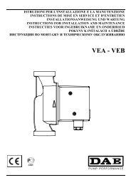
139 – Electropump 294a/294b/294c – Interception valve 127 – Vibration-damping foot<br />
247 – Base 296a/296b/296c – Coupling 298 – <strong>Active</strong> <strong>Driver</strong><br />
291 – Suction manifold 41 – Non return valve 299 – Protection control unit<br />
292 – Delivery manifold 138 – Pressure gauge<br />
15
2 EUROINOX A.D. ...<br />
2 EURO A.D. …<br />
2 JETINOX A.D. ...<br />
2 JET A.D. …<br />
294c<br />
ENGLISH<br />
299 292<br />
138<br />
294b<br />
296c<br />
298<br />
25<br />
296b<br />
294a 41 296a<br />
291<br />
139 127<br />
247<br />
2 K A.D. ...<br />
294c<br />
299 292<br />
138<br />
294b<br />
298<br />
296c<br />
25<br />
296b<br />
294a 41 296a<br />
139<br />
127<br />
291<br />
247<br />
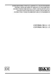
139 – Electropump 292 – Delivery manifold 138 – Pressure gauge<br />
25 – Electropump filling cap 294a/294b/294c – Interception valve 127 – Vibration-damping foot<br />
247 – Base 296a/296b/296c – Coupling 298 – <strong>Active</strong> <strong>Driver</strong><br />
291 – Suction manifold 41 – Non return valve 299 – Protection control unit<br />
16
ENGLISH<br />
CONTENTS<br />
page<br />
1. GENERAL 17<br />
2. WARNINGS 17<br />
2.1. Skilled technical personnel 17<br />
2.2. Safety 17<br />
2.3. Responsibility 17<br />
3. INSTALLATION 17<br />
4. ELECTRICAL CONNECTION 18<br />
5. STARTING UP 18<br />
5.4. Set operating logic 19<br />
5.5. Calibration of the pressure of the set 19<br />
5.6. Stopping of the pumps due to an alarm 19<br />
6. INSTRUCTIONS FOR RUNNING THE SET 20<br />
7. MAINTENANCE 20<br />
7.3. Troubleshooting 20<br />
1. GENERAL<br />
Read this documentation carefully before installation. Installation and functioning must comply with the<br />
safety regulations in force in the country in which the product is installed. The entire operation must be carried<br />
out in a workmanlike manner and exclusively by skilled technical personnel (paragraph 2.1.) in possession of the<br />
qualifications requested by the regulations in force. Failure to comply with the safety regulations not only causes<br />
risk to personal safety and damage to the equipment, but invalidates every right to assistance under guarantee.<br />
Keep this manual with care for further consultation even after the first installation.<br />
2. WARNINGS<br />
2.1. Skilled technical personnel<br />
It is indispensable that installation be carried out by competent, skilled personnel in possession of the<br />
technical qualifications required by the specific legislation in force.<br />
The term skilled personnel means persons whose training, experience and instruction, as well as their<br />
knowledge of the respective standards and requirements for accident prevention and working conditions, have<br />
been approved by the person in charge of plant safety, authorizing them to perform all the necessary activities,<br />
during which they are able to recognize and avoid all dangers. (Definition for technical personnel IEC 364).<br />
2.2. Safety<br />
Use is allowed only if the electric system is in possession of safety precautions in accordance with the regulations in force in<br />
the country where the product is installed (for Italy, CEI 64/2).<br />
2.3. Responsibility<br />
The Manufacturer does not vouch for correct operation of the set or for any damage that it may<br />
cause if it has been tampered with, modified and/or run outside the recommended work range or<br />
without the aid of our control and protection panels.<br />
The Manufacturer declines all responsibility for possible errors in this instructions manual, if<br />
due to misprints or errors in copying. The company reserves the right to make any<br />
modifications to products that it may consider necessary or useful, without affecting the essential<br />
characteristics.<br />
3. INSTALLATION<br />
3.1. The set must be fitted in a well ventilated place, protected from unfavourable weather conditions and with<br />
an environment temperature not exceeding 40°C (fig.1).<br />
When handling the set, lift it by the base.<br />
Do not lift the set by the delivery manifold: risk of damage to the <strong>Active</strong> <strong>Driver</strong> modules!<br />
Position the set in such a way that any maintenance jobs can be carried out without difficulty.<br />
17
ENGLISH<br />
3.2. Ensure that the system pipes are independently supported and do not weigh down on the set manifolds so as<br />
to avoid deformation or breaking of any of its components (fig.2).<br />
It is also advisable to insert vibration-damping couplings on the system manifolds.<br />
3.3. Make the intake section following all the precautions necessary to keep load losses to a minimum and to avoid the<br />
formation of air pockets, for example:<br />
a) Position the set as close as possible to the power supply source.<br />
b) Consider a suction pipe diameter never smaller than that of the manifold.<br />
c) Lay the suction pipe horizontally or sloping slightly upwards towards the set. (fig.3).<br />
d) Avoid using elbows or couplings that cause sudden changes in direction. If necessary, use bends with a wide radius.<br />
e)<br />
Avoid the “siphon” effect at intake: it risks unpriming the pumps!<br />
4. ELECTRICAL CONNECTION<br />
CAUTION! ALWAYS FOLLOW THE SAFETY REGULATIONS!<br />
4.1. The electrical installation must be carried out by a qualified, skilled electrician (see point<br />
2.1.) in compliance with the Safety Regulations in force in the country where the product is<br />
installed.<br />
4.2. Before connecting the power cables to the terminals of the protection control unit, check that the supply<br />
voltage corresponds to the value indicated on the technical data table of the control unit (230 V singlephase,<br />
400 V three-phase + Neutral, 400 V three-phase).<br />
For sets with one pump it is sufficient to insert the plug of the <strong>Active</strong> <strong>Driver</strong> module.<br />
For information on the <strong>Active</strong> <strong>Driver</strong> module, see the enclosed documentation.<br />
4.3. Connect the power cable to the terminal board of the control unit, giving priority to the earth lead.<br />
4.4. To supply the pump set use class A differential switches, with adjustable dispersion current 300mA,<br />
selective and protected against slow tripping (tripping delay 0.5 seconds).<br />
5. STARTING<br />
To start the set correctly, perform the procedure below following the sequence indicated:<br />
5.1.<br />
Perform the following operation without switching on the power to the panel.<br />
5.2.<br />
Check that the moving parts turn freely. To do this, remove the fan cover and, if necessary, the fan; then turn the shaft with<br />
a suitable tool (screw driver, offset adjustable spanner, etc.). (fig. 4)<br />
If it is blocked, tap lightly with a hammer on the end of the tool, then try to turn the shaft again.<br />
Perform the following operation without switching on the power to the panel.<br />
Prime the set as follows:<br />
a) Slowly pour in clean water through a sleeve of the suction manifold, keeping open the filling cap (ref.25) of one of<br />
the electropumps to allow the air inside to get out, until the manifold is filled (fig.5/I).<br />
b) Slowly pour clean water through a coupling of the delivery manifold until water comes out of the loading cap,<br />
removed previously. (fig.5/II)<br />
For sets with KVC pumps with IN-LINE apertures, unscrew the pin of the loading cap as far as it can go, then slowly<br />
pour clean water through a coupling of the delivery manifold until water comes out of the loading cap, removed<br />
previously. (fig.5/II)<br />
The sets with Pulsar Dry pumps are supplied with <strong>Active</strong> <strong>Driver</strong>, valves and delivery manifold dismantled to<br />
facilitate the operation of priming the pumps. Prime each pump, slowly pouring clean water through the delivery<br />
manifold, located at the top of the pump, until the pumps are filled. After this operation fix the <strong>Active</strong> <strong>Driver</strong>,<br />
complete with valves and delivery manifold, to the delivery sleeves of the pumps and secure the couplings.<br />
18
ENGLISH<br />
5.3. In most cases, the set does not need diaphragm expansion vessels. If it should be necessary to have a store of pressurised<br />
water, it is possible to fit the vessel supplied with the set as follows:<br />
1) preload the vessel at a pressure 0.3 bar lower than the starting pressure of the pumps;<br />
2) fit the vessel onto the 1” couplings of the delivery manifold.<br />
For sets with one pump, screw the T coupling, supplied with the set, into the delivery valve, then fit the tank onto the 1”<br />
connector of the T coupling. If fitting the expansion vessel, set the Od parameter of the <strong>Active</strong> <strong>Driver</strong> at “2”.<br />
For information on the <strong>Active</strong> <strong>Driver</strong> module, see the enclosed documentation.<br />
5.4. SET OPERATING LOGIC<br />
The operating logic of the pump set you have bought is to supply Constant Pressure as the water flow rate required by<br />
the system varies. This is made possible by the <strong>Active</strong> <strong>Driver</strong> module fitted on each pump.<br />
It is advisable to set all the pumps at the same desired pressure value. At the first fall of pressure in the system, due to water<br />
being drawn, the first pump starts. When the required flow rate rises, the second and/or the third pump starts in cascade.<br />
The pumps stop in inverse order, after the decrease of the water flow rate.<br />
At the second fall of pressure in the system, thanks to an alternating system in the starting of the pumps, the second pump<br />
starts. When the required flow rate rises, the first and/or third pump starts in cascade. The pumps stop in inverse order, after<br />
the decrease of the water flow rate.<br />
For further information on the methods of alternation in the starting of the pumps, see the documentation enclosed with the<br />
<strong>Active</strong> <strong>Driver</strong> module.<br />
5.5. CALIBRATION OF THE PRESSURE OF THE SET<br />
a) Switch on the pump 1 by means of the switch on the protection control unit (for sets with one pump it is sufficient to<br />
insert the plug of the <strong>Active</strong> <strong>Driver</strong> module).<br />
The display shows “GO” during operation and “Sb” when stopping.<br />
b) Press the MODE / SET keys simultaneously for a few seconds.<br />
c) The letters “SP” appear on the display, check whether the pressure value already set corresponds to the desired value;<br />
otherwise change it, pressing the + or – keys (range 1.0 / 9.0 bar).<br />
d) Press SET to return to normal operating status.<br />
e) Partly turn on the supply and check on the display or pressure gauge that the pressure remains constant when the water<br />
supply increases or decreases (remaining within the limits of the pump’s performance).<br />
f) Repeat the procedure described in points a), b), c), d) e) for pump 2 and pump 3.<br />
By pressing only the MODE key it is possible to view the following parameters:<br />
Fr = pump operation frequency;<br />
UP = instantaneous pressure (bar);<br />
C1 = current absorbed by the pump (A).<br />
For other operating parameters see the documentation enclosed with the <strong>Active</strong> <strong>Driver</strong> module.<br />
5.6. STOPPING OF THE PUMPS DUE TO AN ALARM<br />
The pumps are stopped automatically in the following conditions:<br />
1. Lack of water at pump intake (dry running) for a time higher than 10 seconds (adjustable).<br />
2. Low supply voltage.<br />
3. Overheating of the internal components of the <strong>Active</strong> <strong>Driver</strong>.<br />
4. Excess current in the pump.<br />
The pumps start again automatically when the conditions described above cease.<br />
For further information see the documentation enclosed with the <strong>Active</strong> <strong>Driver</strong> module.<br />
5.7. If it should be necessary to stop the pumps when a certain pressure is exceeded, it is possible to install a pressure switch on<br />
the delivery manifold, calibrated in such a way that it indicates when the pressure has been exceeded.<br />
The contact of the pressure switch must be connected to the terminal board J22 of the <strong>Active</strong> <strong>Driver</strong> (inlet I3).<br />
For further information see the documentation enclosed with the <strong>Active</strong> <strong>Driver</strong> module.<br />
19
ENGLISH<br />
6. INSTRUCTIONS FOR RUNNING THE SET<br />
6.1. When the set remains inactive for long periods at a temperature below 0°C, it must be drained<br />
completely. (fig.7)<br />
7 MAINTENANCE<br />
7.1. To dismantle the <strong>Active</strong> <strong>Driver</strong> module:<br />
a) switch off the power supply and wait a few minutes;<br />
b) close the interception valves upstream and downstream from the module;<br />
c) drain off the water by means of the drainage cap on the rear of the <strong>Active</strong> <strong>Driver</strong>;<br />
d) slacken the unions upstream and downstream and extract the module.<br />
After reassembling the module, fix the unions, open the interception valves again and prime the set as in points 5.2 a) and b).<br />
The <strong>Active</strong> <strong>Driver</strong> must be calibrated as in the enclosed instruction manual.<br />
7.2. All our sets are subjected to strict testing of both the electrical and the hydraulic part.<br />
It is unusual for malfunctions to occur, unless due to external or completely accidental causes.<br />
7.3. Below is a table with some suggestions on regulating the set in the event of irregularities in operation.<br />
FAULTS POSSIBLE CAUSES REMEDIES<br />
THE SET DOES NOT PRIME. 1.<br />
2.<br />
3.<br />
4.<br />
5.<br />
Suction pipe with insufficient diameter;<br />
excessive us of couplings which cause<br />
sudden variations in direction of the<br />
suction pipe; siphon effect.<br />
Suction pipe clogged.<br />
Air infiltrations in the suction pipe of the<br />
set.<br />
Foot valve clogged or blocked.<br />
Water recycling between the pumps in<br />
the set.<br />
1.<br />
2.<br />
3.<br />
4.<br />
5.<br />
Check that the suction pipe is correctly<br />
made, as indicated in the paragraph on<br />
"Installation".<br />
Clean it or change it.<br />
Testing under pressure, check the perfect<br />
seal in the couplings, the joins and the<br />
pipes.<br />
Clean it or change it.<br />
Check correct operation of the non return<br />
valves on suction of each pipe.<br />
6.<br />
Interception valves on suction of each<br />
pump partly closed.<br />
6.<br />
Open them completely.<br />
THE SET DOES NOT START. 1.<br />
2.<br />
3.<br />
Under-voltage or excess voltage.<br />
Incorrect value of the rated current set in<br />
the electropump.<br />
The circuit in the <strong>Active</strong> <strong>Driver</strong> is<br />
interrupted.<br />
1.<br />
2.<br />
3.<br />
Check the voltage.<br />
Set the correct current value*.<br />
Look for the point of interruption.<br />
THE SET DOES NOT STOP. 1. Important water leaks in the system. 1. Check the joins, couplings and pipes.<br />
THE SET DOES NOT SUPPLY<br />
THE REQUIRED<br />
CHARACTERISTICS.<br />
1.<br />
2.<br />
3.<br />
4.<br />
5.<br />
6.<br />
7.<br />
8.<br />
The set chosen is undersized for the<br />
characteristics of the system.<br />
Excessive water consumption for the<br />
flow rate of the well (set above head) or<br />
of the first collection tank (set below<br />
head or above head).<br />
One or more pumps clogged.<br />
Pipes clogged.<br />
Foot valve clogged or blocked (set<br />
above head).<br />
Water recycling between the pumps in<br />
the set.<br />
Interception valves at suction and<br />
delivery of each pump partly closed.<br />
Air infiltrations in the suction pipe of the<br />
set.<br />
1.<br />
2.<br />
3.<br />
4.<br />
5.<br />
6.<br />
7.<br />
8.<br />
Change it, consulting the Technical<br />
Catalogue.<br />
Increase the flow rate that can be supplied<br />
by the well or by the first collection tank.<br />
Dismantle them and clean the pump body<br />
and the impellers, ensuring that they are in<br />
good condition.<br />
Clean them or change them.<br />
Clean it or change it.<br />
Check correct operation of the non return<br />
valves at suction of each pump.<br />
Open them completely.<br />
Testing under pressure, check the perfect<br />
seal in the couplings, the joins and the<br />
pipes.<br />
20
ENGLISH<br />
FAULTS POSSIBLE CAUSES REMEDIES<br />
ONE OR MORE PUMPS IN THE<br />
SET, WHEN STOPPED, TURN IN<br />
THE OPPOSITE DIRECTION.<br />
1.<br />
2.<br />
The respective non return or foot valves<br />
do not close well or are blocked.<br />
The respective suction pipe is not<br />
hermetically sealed.<br />
1.<br />
2.<br />
Check its seal and correct operation.<br />
Testing under pressure, check the seal.<br />
THE MOTOR OF A PUMP IN THE<br />
SET IS VIBRATING.<br />
1.<br />
2.<br />
3.<br />
Pump blocked.<br />
Worn bearings.<br />
Electric cables interrupted.<br />
1.<br />
2.<br />
3.<br />
Release the pump.<br />
Change the bearings.<br />
Change the cables.<br />
WATER HAMMER IN THE<br />
SYSTEM.<br />
1.<br />
2.<br />
Water hammer during operation of the<br />
set.<br />
Water hammer when turning off the<br />
flow.<br />
1.<br />
2.<br />
Check the non return valve of the hot water<br />
distribution mains.<br />
Install other aquaboxes or water hammer<br />
deadening devices at the end of the pipe<br />
where the phenomenon occurs.<br />
A PUMP IN THE SET STOPS AND<br />
DOES NOT START AGAIN.<br />
1.<br />
2.<br />
3.<br />
The protection of the <strong>Active</strong> <strong>Driver</strong> has<br />
tripped.<br />
Electropump blocked.<br />
Presence of faults in the <strong>Active</strong> <strong>Driver</strong>.<br />
1.<br />
2.<br />
3.<br />
Check the absorption of the electropump.<br />
Release the electropump.<br />
Check the errors in the <strong>Active</strong> <strong>Driver</strong>*.<br />
If necessary, change the <strong>Active</strong> <strong>Driver</strong>.<br />
GREAT PRESSURE OSCILLATIONS<br />
IN THE SYSTEM.<br />
1.<br />
2.<br />
Suction pipe too long.<br />
GP and GI parameters need regulating.<br />
1.<br />
2.<br />
Check suction.<br />
Set a new value for GP and GI.<br />
If necessary add a diaphragm expansion<br />
tank on the delivery manifold and set “2” in<br />
the Od parameter of the <strong>Active</strong> <strong>Driver</strong>*.<br />
* To regulate / check the parameters, see the documentation enclosed with the <strong>Active</strong> <strong>Driver</strong> module.<br />
21