

CBX32M Air Handler Installation Manual - Lennox
CBX32M Air Handler Installation Manual - Lennox
CBX32M Air Handler Installation Manual - Lennox

Create successful ePaper yourself
Turn your PDF publications into a flip-book with our unique Google optimized e-Paper software.
2011 <strong>Lennox</strong> Industries Inc.<br />
Dallas, Texas, USA<br />
WARNING<br />
Improper installation, adjustment, alteration,<br />
service or maintenance can cause personal injury,<br />
loss of life, or damage to property.<br />
<strong>Installation</strong> and service must be performed by a<br />
licensed professional installer (or equivalent) or a<br />
service agency.<br />
CAUTION<br />
Physical contact with metal edges and corners<br />
while applying excessive force or rapid motion can<br />
result in personal injury. Be aware of, and use<br />
caution when working near these areas during<br />
installation or while servicing this equipment.<br />
IMPORTANT<br />
The Clean <strong>Air</strong> Act of 1990 bans the intentional<br />
venting of refrigerant (CFCs, HCFCs and HFCs) as<br />
of July 1, 1992. Approved methods of recovery,<br />
recycling or reclaiming must be followed. Fines<br />
and/or incarceration may be levied for<br />
noncompliance.<br />
INSTALLATION<br />
INSTRUCTIONS<br />
Elite ® Series <strong>CBX32M</strong> Units<br />
AIR HANDLER<br />
506150−01<br />
07/11<br />
Supersedes 05/09<br />
RETAIN THESE INSTRUCTIONS<br />
FOR FUTURE REFERENCE<br />
Table of Contents<br />
<strong>CBX32M</strong> Upflow/Downflow Unit Dimensions . . . . . . 2<br />
<strong>CBX32M</strong> Horizontal LH/RH Unit Dimensions . . . . . . 3<br />
General Information . . . . . . . . . . . . . . . . . . . . . . . . . . . 3<br />
Shipping and Packing List . . . . . . . . . . . . . . . . . . . . . . 3<br />
Requirements . . . . . . . . . . . . . . . . . . . . . . . . . . . . . . . . . 3<br />
Installing the Unit . . . . . . . . . . . . . . . . . . . . . . . . . . . . . . 4<br />
Brazing Connections . . . . . . . . . . . . . . . . . . . . . . . . . . . 7<br />
Installing the Condensate Drain . . . . . . . . . . . . . . . . . 8<br />
Inspecting and Replacing Filters . . . . . . . . . . . . . . . . . 9<br />
Making Electrical Connections . . . . . . . . . . . . . . . . . . 9<br />
Sealing the Unit . . . . . . . . . . . . . . . . . . . . . . . . . . . . . . . 14<br />
Adjusting the Blower Speed . . . . . . . . . . . . . . . . . . . . 14<br />
Repairing or Replacing Cabinet Insulation . . . . . . . . . 18<br />
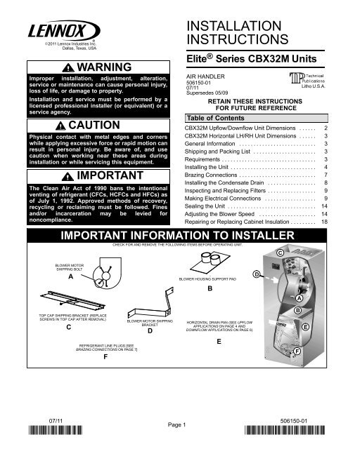
IMPORTANT INFORMATION TO INSTALLER<br />
CHECK FOR AND REMOVE THE FOLLOWING ITEMS BEFORE OPERATING UNIT.<br />
Litho U.S.A.<br />
BLOWER MOTOR<br />
SHIPPING BOLT<br />
A<br />
BLOWER HOUSING SUPPORT PAD<br />
B<br />
TOP CAP SHIPPING BRACKET (REPLACE<br />
SCREWS IN TOP CAP AFTER REMOVAL)<br />
C<br />
REFRIGERANT LINE PLUGS [SEE<br />
BRAZING CONNECTIONS ON PAGE 7]<br />
F<br />
BLOWER MOTOR SHIPPING<br />
BRACKET<br />
D<br />
HORIZONTAL DRAIN PAN (SEE UPFLOW<br />
APPLICATIONS ON PAGE 4 AND<br />
DOWNFLOW APPLICATIONS ON PAGE 6)<br />
E<br />
07/11 506150−01<br />
Page 1
<strong>CBX32M</strong> Upflow and Downflow Unit Dimensions − Inches (mm)<br />
Dimension<br />
<strong>CBX32M</strong> Model Dimensions (for Upflow, Downflow, LH and RH Horizontal Applications)<br />
−018/−024 −030 −036 −042 −048/−060<br />
inches mm inches mm inches mm inches mm inches mm<br />
A 45−1/4 1149 49−1/4 1251 51 1295 52−1/2 1333 58-1/2 1486<br />
B 16−1/4 413 21−1/4 540 21-1/4 540 21-1/4 540 21-1/4 540<br />
C 20−5/8 524 20−5/8 524 22-5/8 575 22-5/8 575 24-5/8 625<br />
D 14−3/4 375 19−3/4 502 19-3/4 502 19-3/4 502 19-3/4 502<br />
E 19 483 19 483 21 533 21 533 23 584<br />
F 15 381 20 508 20 508 20 508 20 508<br />
G 24−5/8 625 24−5/8 625 26-3/8 670 27-7/8 708 27-7/8 708<br />
H 20−5/8 524 24−5/8 625 24-5/8 625 24-5/8 625 30-5/8 778<br />
3/4<br />
(19)<br />
SUPPLY<br />
AIR OPENING<br />
PIPING PLATE DETAIL<br />
(FOR UPFLOW AND DOWNFLOW POSITIONS)<br />
1-1/8 (29) 4-3/8 (111)<br />
5/8 (16)<br />
11-1/16<br />
(281)<br />
D<br />
LINE VOLTAGE<br />
INLETS (TOP<br />
AND LEFT SIDE)<br />
Top View<br />
B<br />
3/4<br />
(19)<br />
LOW VOLTAGE<br />
INLETS (TOP AND RIGHT<br />
SIDE)<br />
5/8<br />
(16)<br />
2<br />
(51)<br />
5-3/8<br />
(137)<br />
C<br />
2-3/4<br />
(70)<br />
1-3/4 (44)<br />
SUCTION LINE<br />
CONDENSATE<br />
DRAINS (2)<br />
(HORIZONTAL)<br />
LIQUID LINE<br />
CONDENSATE<br />
DRAINS (2)<br />
(UPFLOW AND<br />
DOWNFLOW)<br />
3-1/2 (89)<br />
C<br />
5/8<br />
(16)<br />
E<br />
1 (25)<br />
F<br />
Return<br />
<strong>Air</strong> Opening<br />
Top View<br />
B<br />
5/8<br />
(16)<br />
FILTER<br />
ACCESS<br />
5/8<br />
(16)<br />
<strong>Air</strong> Flow<br />
Return <strong>Air</strong><br />
F<br />
Front View<br />
5/8<br />
(16)<br />
G<br />
H<br />
A<br />
FILTER<br />
ACCESS<br />
OPTIONAL<br />
ELECTRIC<br />
HEAT<br />
(FIELD−<br />
INSTALLED)<br />
SUCTION<br />
LINE<br />
LIQUID<br />
LINE<br />
FILTER<br />
Upflow Position<br />
1<br />
(25)<br />
Blower<br />
Coil<br />
Return <strong>Air</strong><br />
E<br />
Side View<br />
5/8<br />
(16)<br />
FILTER<br />
SUCTION<br />
LINE<br />
LIQUID<br />
LINE<br />
OPTIONAL<br />
ELECTRIC<br />
HEAT (FIELD−<br />
INSTALLED)<br />
LOW VOLTAGE<br />
(RIGHT SIDE)<br />
LINE VOLTAGE<br />
(LEFT SIDE)<br />
11-1/16 (281)<br />
Coil<br />
Blower<br />
Supply <strong>Air</strong><br />
Side View<br />
5/8<br />
(16)<br />
5/8<br />
(16)<br />
<strong>Air</strong> Flow<br />
Supply <strong>Air</strong><br />
D<br />
Front View<br />
Downflow Position<br />
(KIT NUMBER 83M57 (LB−909844A) REQUIRED TO CONVERT<br />
UNIT TO DOWNFLOW APPLICATIONS.)<br />
H<br />
G<br />
A<br />
5/8 (16)<br />
Page 2<br />
506150−01 07/11
<strong>CBX32M</strong> Horizontal Left− and Right−Hand Unit Dimensions − Inches (mm)<br />
5-3/8<br />
(137)<br />
2<br />
(51)<br />
LIQUID<br />
LINE<br />
Filter<br />
CONDENSATE<br />
DRAINS (2)<br />
(UPFLOW AND<br />
DOWNFLOW)<br />
CONDENSATE<br />
DRAINS (2)<br />
(HORIZONTAL)<br />
PIPING PLATE<br />
DETAIL<br />
5/8<br />
(16)<br />
5/8<br />
(16)<br />
5-3/4<br />
(46)<br />
1-3/4<br />
(44)<br />
E<br />
Return<br />
F <strong>Air</strong> Opening<br />
1-1/2<br />
(38)<br />
1<br />
(25)<br />
SUCTION<br />
LINE<br />
1-1/8<br />
(29)<br />
4-3/8<br />
(111)<br />
LIQUID<br />
LINE<br />
Coil<br />
SUCTION<br />
LINE<br />
H<br />
Top View<br />
A<br />
<strong>Air</strong><br />
Flow<br />
Blower<br />
B<br />
C<br />
OPTIONAL ELECTRIC<br />
HEAT (FIELD−INSTALLED)<br />
G<br />
5/8<br />
(16)<br />
LINE VOLTAGE<br />
INLETS (TOP<br />
AND RIGHT<br />
SIDE)<br />
FOR DIMENSIONS A" THROUGH<br />
H", SEE CHART ON PAGE 2.<br />
11-1/16<br />
(281)<br />
Supply<br />
<strong>Air</strong><br />
Opening<br />
3/4<br />
(19)<br />
D<br />
3/4<br />
(19)<br />
5/8<br />
(16)<br />
End View<br />
FILTER ACCESS<br />
Front View<br />
Horizontal Position (Right-Hand <strong>Air</strong> Discharge)<br />
LOW VOLTAGE<br />
INLETS (BOTTOM<br />
AND RIGHT<br />
SIDE)<br />
End View<br />
3/4<br />
(19)<br />
C<br />
Blower<br />
Coil<br />
4-3/8<br />
(111)<br />
PIPING PLATE<br />
DETAIL<br />
1-1/8<br />
(29)<br />
3/4<br />
(19)<br />
3/4<br />
(19)<br />
LOW VOLTAGE<br />
INLETS (TOP<br />
AND LEFT SIDE)<br />
11-1/16<br />
(281)<br />
OPTIONAL ELECTRIC<br />
HEAT (FIELD INSTALLED)<br />
5/8 (16)<br />
G<br />
A<br />
FILTER<br />
Top View<br />
SUCTION<br />
LINE<br />
H<br />
LIQUID<br />
LINE<br />
SUCTION<br />
LINE<br />
LIQUID<br />
LINE<br />
2<br />
(51)<br />
5/8<br />
(16)<br />
5-3/8<br />
(137)<br />
3/4<br />
(19)<br />
General<br />
D<br />
Supply<br />
<strong>Air</strong> Opening<br />
LINE VOLTAGE INLETS<br />
(BOTTOM AND LEFT SIDE)<br />
End View<br />
B<br />
<strong>Air</strong> Flow<br />
CONDENSATE DRAINS (2)<br />
(HORIZONTAL)<br />
The <strong>Lennox</strong> Elite ® Series <strong>CBX32M</strong> air handler units are<br />
designed for installation with a matched remote outdoor<br />
unit that is charged with HFC−410A refrigerant and optional<br />
field−installed electric heat. The air handler units are for<br />
indoor installation only.<br />
These instructions are intended as a general guide and do<br />
not supersede local or national codes in any way. Consult<br />
authorities having jurisdiction before installation. Check<br />
equipment for shipping damage; if found, immediately<br />
report damage to the last carrier.<br />
Front View<br />
1-3/4<br />
(44)<br />
5-3/4<br />
(146)<br />
FILTER<br />
ACCESS<br />
1-1/2<br />
(38)<br />
Horizontal Position (Left-Hand <strong>Air</strong> Discharge)<br />
1<br />
(25)<br />
Shipping and Packing List<br />
E<br />
F<br />
Return<br />
<strong>Air</strong> Opening<br />
Package 1 of 1 contains the following:<br />
1Assembled air handler unit<br />
Requirements<br />
End View<br />
5/8<br />
(16)<br />
5/8<br />
(16)<br />
In addition to conforming to manufacturer’s installation<br />
instructions and local municipal building codes, installation<br />
of <strong>Lennox</strong> air handler units (with or without optional electric<br />
heat), shall conform with the following National Fire<br />
Protection Association (NFPA) standards:<br />
NFPA No. 90A − Standard for <strong>Installation</strong> of <strong>Air</strong><br />
Conditioning and Ventilation Systems<br />
Page 3<br />
<strong>CBX32M</strong> SERIES
NFPA No. 90B − Standard for <strong>Installation</strong> of Residence<br />
Type Warm <strong>Air</strong> Heating and <strong>Air</strong> Conditioning Systems<br />
This unit is approved for installation clearance to<br />
combustible material as stated on the unit rating plate.<br />
Accessibility and service clearances must take<br />
precedence over combustible material clearances.<br />
Installing the Unit<br />
<strong>CBX32M</strong> units are factory−configured for upflow or<br />
horizontal right−hand discharge installation. For downflow<br />
or horizontal left−hand discharge, some field modification<br />
is required.<br />
WARNING<br />
Electric Shock Hazard.<br />
Can cause injury or death.<br />
Foil-faced insulation has conductive<br />
characteristics similar to metal. Be sure there are no<br />
electrical connections within a ½" of the insulation.<br />
If the foil-faced insulation comes in contact with<br />
electrical voltage, the foil could provide a path for<br />
current to pass through to the outer metal cabinet.<br />
While the current produced may not be enough to<br />
trip existing electrical safety devices (e.g. fuses or<br />
circuit breakers), the current can be enough to<br />
cause an electric shock hazard that could cause<br />
personal injury or death.<br />
WARNING<br />
Improper installation, adjustment, alteration,<br />
service or maintenance can cause property damage,<br />
personal injury or loss of life. <strong>Installation</strong> and<br />
service must be performed by a qualified installer or<br />
service agency.<br />
IMPORTANT<br />
Kit number 83M57 (LB−109844A) must be installed<br />
for downflow application.<br />
DISASSEMBLE AND REASSEMBLE AIR HANDLER<br />
UNIT<br />
The <strong>CBX32M</strong> air handler unit consists of two sections<br />
which are shipped assembled from the factory. If<br />
necessary, the unit may be disassembled to facilitate<br />
setting the unit. Follow the steps below:<br />
To disassemble:<br />
1. Remove access panels.<br />
2. Remove both blower and coil assemblies. This will<br />
lighten the cabinet for lifting.<br />
3. Remove one screw from the left and right posts inside<br />
the unit. Remove one screw from each side on the<br />
back of the unit. Unit sections will now separate.<br />
To reassemble:<br />
1. Align cabinet sections together.<br />
2. Reinstall screws.<br />
3. Replace blower and coil assemblies.<br />
4. Replace access panel.<br />
UPFLOW APPLICATION<br />
Use the following procedures to configure the unit for<br />
upflow operations:<br />
1. Remove access panels. Remove corrugated padding<br />
from the space between the blower and coil<br />
assemblies.<br />
2. The horizontal drain pan must be removed when the<br />
coil blower is installed in the upflow position. Removing<br />
horizontal drain pain will allow proper airflow and<br />
increase efficiency.<br />
3. Place unit in desired location. Make sure that unit is<br />
level. Connect return and supply air plenums as<br />
required using sheet metal screws as illustrated in<br />
figure 1.<br />
4. Install units which have no return air plenum on a<br />
mounting stand that is at least 14" from the floor for<br />
proper air return. <strong>Lennox</strong> offers an optional upflow unit<br />
stand as listed in table 1.<br />
UPFLOW/<br />
DOWNFLOW<br />
DRAIN PAN<br />
HORIZONTAL DRAIN PAN<br />
(MUST BE REMOVED)<br />
Figure 1. Upflow Configuration<br />
Table 1. Optional Unit Side Stand (Upflow Only)<br />
Model<br />
Kit Number<br />
−018 and −024<br />
45K31<br />
−036, −042, −048 and −060 45K32<br />
UPFLOW/<br />
DOWNFLOW<br />
DRAIN PAN<br />
HORIZONTAL<br />
DRAIN PAN<br />
NO ADJUSTMENT IS NECESSARY<br />
HORIZONTAL DRIP SHIELD<br />
Figure 2. Right−Hand Discharge Configuration<br />
Page 4<br />
506150−01 07/11
ANGLE IRON OR<br />
SHEET METAL<br />
1/2 IN.<br />
SCREWS<br />
MAX.<br />
ELECTRICAL INLET<br />
CLEARANCE 4 IN. (102 MM)<br />
2. Remove drain plugs from back drain holes on<br />
horizontal drain pan and reinstall them on front holes.<br />
IMPORTANT<br />
After removal of drain pan plug(s), check drain<br />
hole(s) to verify that drain opening is fully open and<br />
free of any debris. Also check to make sure that no<br />
debris has fallen into the drain pan during installation<br />
that may plug up the drain opening.<br />
FRONT VIEW<br />
END VIEW<br />
Figure 3. Suspending Horizontal Unit<br />
CAUTION<br />
When removing the coil, there is possible danger of<br />
equipment damage and personal injury. Be careful<br />
when removing the coil assembly from a unit<br />
installed in right− or left−hand applications. The coil<br />
may tip into the drain pan once it is clear of the<br />
cabinet. Support the coil when removing it.<br />
HORIZONTAL RIGHT−HAND DISCHARGE<br />
APPLICATION<br />
Use the following procedures to configure the unit for<br />
horizontal right−hand discharge operations:<br />
NOTE − For horizontal applications, an secondary drain<br />
pan is recommended. Refer to local codes.<br />
1. Remove access panels. Remove corrugated padding<br />
from the space between the blower and coil assembly.<br />
2. No further adjustment is necessary. Set unit so that it is<br />
sloped 1/4 inch toward the drain pan end of the unit as<br />
illustrate in figure 2 on page 4.<br />
3. If the unit is to be suspended, it must be supported<br />
along the entire length of the cabinet as illustrated in<br />
figure 3. If a strap is used, attach a piece of angle iron<br />
or sheet metal to the unit (either above or below) so<br />
that the full length of the cabinet is supported. Use<br />
securing screws which are no longer than 1/2 inch to<br />
avoid damaging the coil or filter. Connect the return<br />
and supply air plenums as required using sheet metal<br />
screws.<br />
HORIZONTAL LEFT−HAND DISCHARGE<br />
APPLICATION<br />
Use the following procedures to configure the unit for<br />
horizontal left−hand discharge operations:<br />
NOTE − For horizontal applications, an secondary drain<br />
pan is recommended. Refer to local codes.<br />
Remove access panels. Remove corrugated padding from<br />
the space between the blower and coil assembly before<br />
operation.<br />
1. Remove coil assembly from unit and remove the<br />
horizontal drain pan as illustrated in figure 4, detail A<br />
on page 6.<br />
3. Rotate the drain pan 180° front to back and install it on<br />
the opposite side of coil.<br />
4. Remove screws from top cap. Remove horizontal drip<br />
shield screw located in the center of the back coil end<br />
seal as illustrated in figure 4, details B and C on page<br />
6.<br />
5. Rotate horizontal drip shield 180° front to back.<br />
6. Remove plastic plug from left hole on coil front end<br />
seal and reinstall plug in back hole. Reinstall horizontal<br />
drip shield screw in front coil end seal. Drip shield<br />
should drain downward into horizontal drain pan inside<br />
coil.<br />
7. Rotate top cap 180° front to back and align with<br />
unused screw holes. Holes must align with front and<br />
back coil end plates. Note that top cap has a 45° bend<br />
on one side and 90° bend on the other. The 90° bend<br />
must be on the same side as the horizontal drain pan<br />
as illustrated in figure 4 on page 6.<br />
NOTE − Be very careful when you reinstall the screws into<br />
coil end plate engaging holes. Misaligned screws may<br />
damage the coil.<br />
8. From the upflow position, flip cabinet 90° to the left and<br />
set into place. Replace blower assembly. Secure coil<br />
in place by bending down tab on cabinet support rail<br />
as illustrated in figure 5 on page 6.<br />
NOTE − For horizontal applications in high humidity<br />
areas, seal around the exiting drain pipe, liquid line and<br />
suction line to prevent infiltration of humid air.<br />
9. Knock out drain seal plate from access door. Secure<br />
plate to cabinet front flange with screw provided.<br />
10. Flip access door and replace it on the unit.<br />
11. Set unit so that it is sloped 1/4 inch toward the drain<br />
pan end of the unit. Connect return and supply air<br />
plenums as required using sheet metal screws.<br />
12. If the unit is to be suspended, it must be supported<br />
along the entire length of the cabinet as illustrated in<br />
figure 3 on page 5. If using a chain or strap, attach a<br />
piece of angle iron or sheet metal to the unit (either<br />
above or below the unit), so that the full length of the<br />
cabinet is supported. Use securing screws which are<br />
no longer than 1/2 inch to avoid damaging the coil or<br />
filter. Use sheet metal screws to connect the return<br />
and supply air plenums.<br />
Page 5<br />
<strong>CBX32M</strong> SERIES
COIL SHOWN IN UPFLOW<br />
POSITION FOR EASY<br />
CONVERSION<br />
TOP CAP ROTATED TO<br />
CORRECT POSITION<br />
TOP CAP<br />
SCREWS<br />
DETAIL B<br />
(TOP CAP)<br />
DETAIL A<br />
(DRAIN PAN)<br />
CABINET<br />
SUPPORT<br />
PLUGGED<br />
END<br />
90<br />
BEND<br />
OPEN END FOR<br />
CONDENSATION<br />
DRAIN<br />
COIL<br />
ASSEMBLY<br />
ORIGINAL<br />
PLUG<br />
LOCATION<br />
NEW PLUG<br />
LOCATION<br />
TOP CAP<br />
DETAIL C<br />
ALIGN HOLES WITH<br />
HOLES IN COIL END<br />
PLATE.<br />
90<br />
BEND<br />
BACK COIL END SEAL<br />
DRAIN PAN<br />
Figure 4. Left-Hand Discharge Modifications<br />
SECURING TAB ON<br />
CABINET SUPPORT RAIL<br />
HORIZONTAL DRIP SHIELD<br />
AIR HANDLER<br />
UNIT<br />
HORIZONTAL<br />
DRAIN PAN<br />
Figure 5. Left−Hand Discharge Configuration<br />
DOWNFLOW APPLICATION<br />
Use the following procedures to configure the unit for<br />
downflow operations:<br />
WARNING<br />
If electric heat section with circuit breakers (ECB29)<br />
are applied to downflow <strong>CBX32M</strong> unit, circuit<br />
breakers must be rotated 180 to the UP position.<br />
See ECB29 installation instructions for more<br />
details.<br />
NOTE − If downflow application is required, separately<br />
order kit number 83M57 and install per kit’s instructions.<br />
Also, use metal or class I supply and return air plenums.<br />
On combustible flooring, use an additive base as<br />
illustrated in figure 6. and use the following procedures:<br />
PROPERLY−SIZED<br />
FLOOR OPENING<br />
COMBUSTIBLE FLOOR<br />
ADDITIVE BASE<br />
Figure 6. Combustible Flooring Additive Base<br />
1. Cut an appropriately sized opening for combustible<br />
base as illustrated figure 7.<br />
2. Set the additive base into opening.<br />
3. Connect supply air plenum to the additive base.<br />
4. Set the unit on the additive base so flanges of the unit<br />
drop into the base opening and seal against the<br />
insulation strips. The unit is now locked in place.<br />
5. Install return air plenum and secure with sheet metal<br />
screws.<br />
Page 6<br />
506150−01 07/11
5/8 (16)<br />
1-5/8 (41)<br />
15 (381)<br />
<strong>CBX32M</strong>−21/26<br />
and 31<br />
CB30M−21/26<br />
20 (508)<br />
<strong>CBX32M</strong>−41 to −65<br />
CB30M−31 to 65<br />
1-5/8 (41)<br />
11-3/8<br />
(289)<br />
1-5/8 (41)<br />
SUPPLY<br />
AIR<br />
OPENING<br />
TOP VIEW<br />
22-1/8 (562)<br />
13-3/8 (340)<br />
OPENING<br />
SIDE VIEW<br />
18−1/4 (464)<br />
<strong>CBX32M</strong>−21/26<br />
and 31<br />
CB30M−21/26<br />
23−1/4 (591)<br />
<strong>CBX32M</strong>−41 to −65<br />
CB30M−31 to 65<br />
2 (51)<br />
inches<br />
(mm)<br />
Figure 7. Downflow Combustible Base Dimensions<br />
If the homeowner reports water dripping from supply air<br />
diffusers, check the shields and tape. Make sure the tape is<br />
completely attached to the edges of the drip shield, and<br />
that the drip shield is wedged firmly in place.<br />
IMPORTANT<br />
To prevent the build up of high levels of nitrogen<br />
when purging, be sure it is done in a well ventilated<br />
area. Purge low pressure nitrogen (1 to 2 psig)<br />
through the refrigerant piping during brazing. This<br />
will help to prevent oxidation and the introduction<br />
of moisture into a system.<br />
All coils are equipped with a factory−installed, internally<br />
mounted check/expansion valve, which is suitable for use<br />
in applications as follows:<br />
valve suitable for HCFC−22 use (<strong>CBX32M</strong> unit)<br />
valve suitable for HFC−410A use (CB30M unit)<br />
The <strong>CBX32M</strong>/CB30M air handler’s coil line sizes are listed<br />
in table 2. Use <strong>Lennox</strong> L15 (sweat) series line sets (refer to<br />
the outdoor unit Engineering Handbook for proper size,<br />
type and application). For field−fabricated refrigerant lines,<br />
see the piping section of the <strong>Lennox</strong> Unit Information<br />
Service <strong>Manual</strong>.<br />
Brazing Connections<br />
AIR HANDLER UNIT<br />
WARNING<br />
Danger of explosion!<br />
Can cause equipment damage, injury,<br />
or death.<br />
When using a high pressure gas such<br />
as dry nitrogen to pressurize a<br />
refrigeration or air conditioning<br />
system, use a regulator that can<br />
control the pressure down to 1 or 2 psig<br />
(6.9 to 13.8 kPa).<br />
SUCTION LINE<br />
LIQUID LINE<br />
Figure 8. Brazing Connections<br />
NOTE − <strong>CBX32M</strong> series evaporators use nitrogen or dry<br />
air as a holding charge. If there is no pressure when the<br />
rubber plugs are removed, check the coil or line set for<br />
leaks before installing. After installation, pull a vacuum<br />
on the line set and coil before releasing the unit charge<br />
into the system.<br />
Page 7<br />
<strong>CBX32M</strong> SERIES
ABOVE<br />
FINISHED<br />
SPACE?<br />
NO<br />
OVERFLOW DRAIN LINE<br />
ALWAYS RUN AN OVERFLOW DRAIN LINE. IF NOT POSSIBLE TO<br />
ROUTE OVERFLOW DRAIN LINE, INSTALL LOW VOLTAGE<br />
OVERFLOW SWITCH KIT. WIRE KIT TO SHUT DOWN<br />
COMPRESSOR PER INSTRUCTIONS.<br />
LENNOX #<br />
X3169<br />
COMPACT OVERFLOW SWITCH WITH 3/4" FEMALE SLIP INLET<br />
AND MALE ADAPTER, TWO PART DESIGN FOR USE WHERE<br />
OBSTRUCTIONS PREVENT DIRECT THREADING<br />
CLEAN OUT<br />
PRESS IN<br />
(DO NOT GLUE)<br />
VENT MUST EXTEND<br />
ABOVE HEIGHT OF<br />
COIL DRAIN PAN BY<br />
TWO INCHES (51MM)<br />
VENT<br />
OVERFLOW<br />
DRAIN<br />
AIR HANDLER DRAIN PAN<br />
MAIN<br />
DRAIN<br />
1" X 3/4" X 3/4"<br />
REDUCING<br />
TEE WITH<br />
PLUG<br />
YES<br />
NOTE WHEN A AIR HANDLER IS LOCATED ABOVE A FINISHED SPACE THE SECONDARY<br />
DRAIN PAN MUST HAVE A LARGER FOOTPRINT THAN THE AIR HANDLER.<br />
SECONDARY<br />
DRAIN PAN<br />
OPTIONAL<br />
SAFETY<br />
PAN<br />
LENNOX* P−TRAP<br />
49P66, J−TRAP #<br />
91P90 OR ANY<br />
PVC SCH 40 P− OR<br />
J−TRAP 3/4"<br />
2"<br />
(51MM)<br />
WHEN A COIL IS LOCATED ABOVE A FINISHED SPACE, A 3/4" (19.1MM) SECONDARY DRAIN<br />
LINE MUST BE:<br />
CONNECTED TO SECONDARY DRAIN PAN<br />
OR<br />
CONNECTED TO THE OVERFLOW DRAIN OUTLET OF THE AIR HANDLER DRAIN PAN.<br />
<br />
PRIMARY AND SECONDARY TRAPS MUST BE DEEP ENOUGH TO OFFSET MAXIMUM STATIC<br />
DIFFERENCES GENERALLY, TWO INCHES (51MM).<br />
*LENNOX P−TRAP 49P66 REQUIRES A LARGER INSTALLATION SPACE THAN THE J−TRAP 91P90.<br />
FOR NEGATIVE PRESSURE COILS (BLOWER<br />
AFTER COIL) TRAPS ARE REQUIRED ON ALL<br />
DRAIN LINES CONNECTED TO COIL.<br />
TRAP DEPTH<br />
TO APPROVED<br />
DRAIN<br />
DRAIN LINE SHOULD<br />
SLOPE A MINIMUM OF<br />
ONE INCH PER 10<br />
FEET (25MM PER 3<br />
METERS)<br />
Figure 9. Typical Condensate Drain Connection<br />
NOTE − See outdoor unit instructions on how to flow 9. Install access panel.<br />
nitrogen through line sets.<br />
Table 2. Refrigerant Line Sets<br />
1. Remove access panel.<br />
<strong>CBX32M</strong> Liquid Vapor/ L10<br />
2. Remove the refrigerant line caps from the refrigerant Units Line No. Suction Line Line Sets<br />
lines.<br />
−018/024 3/8 in 5/8 in L10−26<br />
(8 mm) (16 mm) 20 ft. − 50 ft.<br />
3. Use a wet rag to protect TXV sensing bulb (or remove<br />
(6 m − 15 m)<br />
it) when brazing suction line connections.<br />
−030, −036 3/8 in 3/4 in. L10−41<br />
4. Place a wet rag against piping plate and around the<br />
(10 mm) (19 mm 20 ft. − 50 ft.<br />
suction line connection. The wet rag must be in place<br />
(6 m − 15 m)<br />
to guard against damage to the paint.<br />
−042, −048 3/8 in 7/8 in. L10−65<br />
5. With the wet rag in place, position a field provided<br />
(10 mm) (22 mm) 30 ft. − 50 ft.<br />
(9 m − 15 m)<br />
elbow fitting to the air handler’s suction line and line<br />
set. Start nitrogen flow before brazing.<br />
−060 3/8 in 1−1/8 in. Field<br />
(10 mm) (29 mm) Fabricated<br />
6. After the procedure is completed then remove the wet<br />
rag.<br />
7. Place wet rag against piping plate and around the Installing the Condensate Drain<br />
liquid line connection. Position liquid line elbow to air<br />
handler’s suction line and to line set. Start nitrogen flow<br />
and begin brazing both connections and after<br />
procedure is completed then remove both wet rags.<br />
8. Refer to instructions provided with outdoor unit for leak<br />
testing, evacuating and charging procedures.<br />
506150−01 07/11<br />
Page 8<br />
L15<br />
Line Sets<br />
L15−26<br />
20 ft. − 50 ft.<br />
(6 m − 15 m)<br />
L15−41<br />
20 ft. − 50 ft.<br />
(6 m − 15 m)<br />
L15−65<br />
30 ft. − 50 ft.<br />
(9 m − 15 m)<br />
Field<br />
Fabricated<br />
Before connecting drain line(s), check drain hole(s) to<br />
verify that drain opening is fully open and free of any<br />
debris. Also check to make sure that no debris has fallen<br />
into the drain pan during installation that may plug up the<br />
drain opening.
Connect main condensate drain and route downward to an<br />
open drain or sump. Do not connect drain to a closed waste<br />
system. Refer to figure 9 on page 8 for typical condensate<br />
trap configuration.<br />
It is recommended that the auxiliary drain be connected to<br />
a drain line for all units. If auxiliary drain is not connected, it<br />
must be plugged with provided cap. For downflow units,<br />
the auxiliary drain shall be connected and routed to a drain.<br />
See figure 10 for auxiliary and main drain locations.<br />
The following practices are recommended to ensure<br />
condensate removal as illustrated in figures 9 and 10:<br />
Drain piping should not be smaller than the drain<br />
connections at drain pan.<br />
A trap must be installed in the main drain line.<br />
The trap must be deep enough to offset the difference<br />
in static pressure between drain pan and atmosphere.<br />
Generally, two inches is satisfactory for medium static<br />
applications.<br />
Horizontal runs must be sloped 1 inch per 10 feet of<br />
drain line to offset friction.<br />
An open vent in drain line will sometimes be required due<br />
to line length, friction and static pressure.<br />
Drain construction and routing should facilitate future<br />
cleaning and must not interfere with filter access.<br />
Auxiliary drain should run to an area where<br />
homeowner will notice any drainage.<br />
Left−Hand<br />
Discharge<br />
Auxiliary Drain on Left<br />
Upflow or<br />
Downflow<br />
Figure 10. Drain Locations<br />
Inspecting and Replacing Filters<br />
IMPORTANT<br />
Right−Hand<br />
Discharge<br />
Main Drain on Right<br />
Filter access panel must be in place during unit<br />
operation. Excessive warm air entering the unit may<br />
result in water blow−off problems.<br />
Each unit includes a factory−installed filter. Note that filter<br />
access door fits over access panel. <strong>Air</strong> leakage will occur if<br />
access panel is placed over filter door.<br />
Filters should be inspected monthly and must be cleaned<br />
or replaced when dirty to assure proper furnace operation.<br />
Reusable filters supplied with some units can be washed<br />
with water and mild detergent. Some units are equipped<br />
with standard throw−away type filters which should be<br />
replaced when dirty.<br />
To replace filter:<br />
1. Loosen the thumbscrews holding the filter panel in<br />
place.<br />
2. Slide the filter out of the guides on either side of<br />
cabinet.<br />
3. Insert new filter.<br />
4. Replace panel.<br />
See table 3 for replacement filter sizes.<br />
Table 3. Filter Dimension<br />
Unit Model No. Filter Size Inches (mm)<br />
−018 and −024 15 x 20 (381 x 508)<br />
−030 20 x 20 (508 x 508)<br />
−036 and −042 20 x 22 (508 x 559)<br />
−048 and −060 20 x 24 (508 x 610)<br />
Making Electrical Connections<br />
WARNING<br />
USE COPPER CONDUCTORS ONLY.<br />
Run 24V Class II wiring only through specified low<br />
voltage opening. Run line voltage wiring only<br />
through specified high voltage opening. Do not<br />
combine voltage in one opening.<br />
Wiring must conform to the current National Electric Code<br />
ANSI/NFPA No. 70, or Canadian Electric Code Part I, CSA<br />
Standard C22.1, and local building codes. Refer to<br />
following wiring diagrams. See unit nameplate for<br />
minimum circuit ampacity and maximum overcurrent<br />
protection size.<br />
Select the proper supply circuit conductors in<br />
accordance with tables 310−16 and 310−17 in the<br />
National Electric Code, ANSI/NFPA No. 70 or tables 1<br />
through 4 in the Canadian Electric Code, Part I, CSA<br />
Standard C22.1.<br />
This unit is provided with knockouts for conduit. Refer to<br />
figure 15 for unit schematic wiring diagram. Refer to<br />
figures 14 through 13 for typical field wiring.<br />
Separate openings have been provided for 24V low<br />
voltage and line voltage. Refer to the dimension illustration<br />
for specific location.<br />
Page 9<br />
<strong>CBX32M</strong> SERIES
CIRCUIT 1<br />
CIRCUIT BREAKERS<br />
OR TERMINAL BLOCK<br />
4<br />
7<br />
1<br />
CB1<br />
CIRCUIT<br />
BREAKER<br />
OR<br />
FUSE<br />
6<br />
9<br />
3<br />
NOTE − USE COPPER CONDUCTORS ONLY.<br />
REFER TO UNIT RATING PLATE FOR MINIMUM<br />
CIRCUIT AMPACITY AND MAXIMUM OVERCUR-<br />
RENT PROTECTION SIZE.<br />
LINE VOLTAGE FIELD INSTALLED<br />
CLASS 2 VOLTAGE FIELD INSTALLED<br />
NEC/CEC<br />
NOTE − ALL REMAINING WIRES ARE FACTORY<br />
INSTALLED<br />
TO EXTERNAL LOAD 24VAC AT .50 AMP MAXI-<br />
MUM.<br />
THERMOSTAT HEAT ANTICIPATION SETTING 0.4<br />
AMP ELECTRIC HEAT<br />
WHEN TWO−STAGE THERMOSTAT IS USED,<br />
CONNECT SECOND STAGE HEAT BULB TO TER-<br />
MINAL W2" AND REMOVE JUMPER BETWEEN<br />
TERMINALS R" AND W2."<br />
FACTORY INSTALLED JUMPERS<br />
L3 CONNECTION USED ON (Y−VOLTAGE)<br />
3−PHASE ELECTRIC HEATERS ONLY.<br />
Figure 11. Typical Field Wiring − Cooling Application with Electric Heat<br />
4<br />
1<br />
6<br />
3<br />
LINE VOLTAGE FIELD INSTALLED<br />
CLASS 2 VOLTAGE FIELD INSTALLED NEC/CEC<br />
NOTE − ALL REMAINING WIRES ARE FACTORY INSTALLED<br />
TO EXTERNAL LOAD 24VAC AT .50 AMP MAXIMUM<br />
FACTORY INSTALLED JUMPERS<br />
CIRCUIT 1<br />
CIRCUIT BREAKERS<br />
OR TERMINAL BLOCK<br />
7<br />
CB1<br />
CIRCUIT<br />
BREAKER<br />
OR FUSE<br />
9<br />
Y2 USED ONLY WHEN TWO SPEED COMPRESSOR IS USED (HP21).<br />
USING SERVICE LIGHT OPTION (S54) WITH SOME ELECTRONIC<br />
THERMOSTATS MAY REQUIRE MOVING S54 COMMON WIRE TO Y1<br />
IN HEAT PUMP UNIT.<br />
COMMON USED ONLY ON SOME THERMOSTATS.<br />
AMBIENT COMPENSATING THERMISTOR CONNECTION USED ONLY<br />
ON SOME THERMOSTATS.<br />
1<br />
E C W1 G O Y1 R L T<br />
Y2<br />
2<br />
5<br />
3<br />
HEAT PUMP CLASS 2<br />
VOLTAGE TERMINALS<br />
COMMON<br />
C<br />
W1 O Y1 R L T Y2<br />
ELECTRIC HEAT<br />
REVERSING VALVE<br />
COMPRESSOR<br />
POWER<br />
SERVICE LIGHT<br />
THERMISTOR<br />
4 6<br />
2ND STAGE COMPRESSOR<br />
Figure 12. Typical Field Wiring − Heat Pump Only Application<br />
Page 10<br />
506150−01 07/11
4<br />
1<br />
6<br />
3<br />
K22<br />
6<br />
E C W1 G O Y1 R L T<br />
Y2<br />
CIR-<br />
CUIT 1<br />
CIRCUIT BREAKERS<br />
OR TERMINAL BLOCK<br />
7<br />
9<br />
CB1<br />
CIRCUIT<br />
BREAKER<br />
OR FUSE<br />
S23<br />
LINE VOLTAGE FIELD<br />
INSTALLED<br />
CLASS 2 VOLTAGE FIELD<br />
INSTALLED NEC/CEC<br />
NOTE − ALL REMAINING WIRES<br />
ARE FACTORY INSTALLED<br />
THERMOSTAT HEAT ANTICIPATION<br />
SETTING 0.4 AMP ELECTRIC HEAT<br />
7<br />
FACTORY INSTALLED JUMPERS<br />
C W1 O Y1 R L T<br />
Y2<br />
WHEN OUTDOOR THERMOSTAT IS<br />
USED, CONNECT LEADS TO<br />
TERMINALS R" AND W2" AND<br />
REMOVE JUMPER BETWEEN<br />
TERMINALS R’ AND W2."<br />
EMERGENCY HEAT RELAY (USED<br />
ONLY IF OUTDOOR T’STAT IS<br />
USED) FIELD PROVIDED AND<br />
INSTALLED NEW INDOOR UNIT.<br />
24VAC 5VA MAX NEC/CEC CLASS 2<br />
USING SERVICE LIGHT OPTION (S54) WITH SOME ELECTRONIC<br />
THERMOSTATS MAY REQUIRE MOVING S54 COMMON WIRE TO Y1 IN<br />
HEAT PUMP UNIT.<br />
COMMON USED ONLY ON SOME THERMOSTATS.<br />
Y2 USED ONLY WHEN TWO-SPEED COMPRESSOR IS USED (HP21)<br />
AMBIENT COMPENSATING THERMISTOR CONNECTION USED ONLY ON<br />
SOME THERMOSTATS.<br />
HEAT PUMP CLASS 2<br />
VOLTAGE TERMINALS<br />
COMMON<br />
ELECTRIC HEAT<br />
REVERSING VALVE<br />
COMPRESSOR<br />
POWER<br />
SERVICE LIGHT<br />
THERMISTOR<br />
8<br />
2ND STAGE COMPRESSOR<br />
Figure 13. Typical Field Wiring − Heat Pump Application with Electric Heat<br />
CIRCUIT 1<br />
(Black)<br />
(Orange)<br />
4<br />
7<br />
1<br />
6<br />
9<br />
3<br />
NOTE − USE COPPER CONDUCTORS ONLY.<br />
REFER TO UNIT RATING PLATE FOR MINIMUM<br />
CIRCUIT AMPACITY AND MAXIMUM OVERCUR-<br />
RENT PROTECTION SIZE.<br />
LINE VOLTAGE FIELD INSTALLED<br />
CLASS 2 VOLTAGE FIELD INSTALLED<br />
NEC/CEC<br />
NOTE − ALL REMAINING WIRES ARE FACTORY<br />
INSTALLED<br />
TO EXTERNAL LOAD 24VAC AT .50 AMP MAXIMUM.<br />
FIELD−SUPPLIED WIRE NUTS<br />
FACTORY INSTALLED JUMPERS<br />
CB1 CIRCUIT BREAKER OR<br />
FUSE<br />
Figure 14. Typical Field Wiring − Cooling Only Application<br />
Page 11<br />
<strong>CBX32M</strong> SERIES
Figure 15. Typical Wiring Diagram − Single Phase<br />
Page 12<br />
506150−01 07/11
Figure 16. Typical Wiring Diagram − Three Phase<br />
Page 13<br />
<strong>CBX32M</strong> SERIES
Sealing the Unit<br />
WARNING<br />
There must be an airtight seal between the bottom<br />
of the air handler and the return air plenum. Use<br />
fiberglass sealing strips, caulking, or equivalent<br />
sealing method between the plenum and the air<br />
handler cabinet to ensure a tight seal. Return air<br />
must not be drawn from a room where this air<br />
handler or any gas−fueled appliance (i.e., water<br />
heater), or carbon monoxide−producing device (i.e.,<br />
wood fireplace) is installed.<br />
Seal the unit so that warm air is not allowed into the<br />
cabinet. Warm air introduces moisture, which results in<br />
water blow−off problems. This is especially important when<br />
the unit is installed in an unconditioned area.<br />
Make sure the liquid line and suction line entry points are<br />
sealed with either the provided flexible elastomeric thermal<br />
insulation, or field provided material (e.g. Armaflex,<br />
Permagum or equivalent). Any of the previously mention<br />
materials may be used to seal around the main and<br />
auxiliary drains, and around open areas of electrical inlets.<br />
Adjusting the Blower Speed Adjustments<br />
MINIMUM BLOWER SPEEDS (WITH ELECTRIC<br />
HEATERS)<br />
For the minimum allowable speed for the <strong>CBX32M</strong> series<br />
units with electric heat, refer to the ECB29 installation<br />
instructions.<br />
AIR VOLUME ADJUSTMENT<br />
Blower speed selection is accomplished by changing the<br />
taps at the harness connector at the Blower motor as<br />
illustrated in figure 17. Refer to unit wiring diagram in figure<br />
15 on page 12. Refer to tables 4 through 11 for air handler<br />
performance data.<br />
PRESS THE TAB TO RELEASE WIRE CONNECTOR.<br />
SELECT CONNECTOR LOCATION FOR NEW SPEED.<br />
INSERT WIRE UNTIL IT CLICKS.<br />
HARNESS<br />
CONNECTOR<br />
Figure 17. Blower Speed Tap Selection<br />
Table 4. <strong>CBX32M</strong>-018/024 <strong>Air</strong> <strong>Handler</strong> Performance (208/230V)<br />
<strong>Air</strong> Volume and Motor Watts at Specific Blower Taps<br />
Low Medium High<br />
External Static<br />
Pressure<br />
in. w.g. Pa cfm L/s Watts cfm L/s Watts cfm L/s Watts<br />
.00 0 700 330 245 895 425 300 1030 485 365<br />
.05 10 695 330 245 890 420 295 1015 480 360<br />
.10 25 690 325 240 875 415 290 1000 470 355<br />
.15 35 680 320 235 860 405 285 980 465 345<br />
.20 50 665 315 230 845 400 280 960 455 340<br />
.25 60 650 310 220 825 390 275 935 440 335<br />
.30 75 635 300 215 800 380 265 910 430 325<br />
.40 100 590 280 205 745 355 250 850 400 310<br />
.50 125 535 255 190 685 320 235 780 370 295<br />
.60 150 470 220 175 605 285 220 705 330 280<br />
.70 175 395 185 165 520 245 200 615 290 265<br />
.75 185 350 165 155 475 225 195 565 265 255<br />
NOTE − All air data is measured external to unit with air filter in place. Electric heaters have no appreciable air resistance.<br />
506150−01 07/11<br />
Page 14
Table 5. <strong>CBX32M</strong>-030 <strong>Air</strong> <strong>Handler</strong> Performance (208/230V)<br />
<strong>Air</strong> Volume and Motor Watts at Specific Blower Taps<br />
External Static Pressure<br />
Low<br />
High<br />
in. w.g. Pa cfm L/s Watts cfm L/s Watts<br />
.00 0 1120 530 390 1525 720 505<br />
.05 10 1150 540 385 1520 720 495<br />
.10 25 1170 550 380 1510 715 480<br />
.15 35 1180 560 285 1495 705 470<br />
.20 50 1190 560 280 1475 695 455<br />
.25 60 1185 560 275 1450 685 440<br />
.30 75 1175 555 375 1415 670 430<br />
.40 100 1135 535 325 1335 630 400<br />
.50 125 1060 500 300 1230 580 375<br />
.60 150 960 455 280 1100 520 345<br />
.70 175 830 390 255 950 450 320<br />
.75 185 750 355 245 870 410 305<br />
NOTE − All air data is measured external to unit with air filter in place. Electric heaters have no appreciable air resistance.<br />
Table 6. <strong>CBX32M</strong>-036 <strong>Air</strong> <strong>Handler</strong> Performance (208/230V)<br />
External Static<br />
<strong>Air</strong> Volume and Motor Watts at Specific Blower Taps<br />
Pressure<br />
Low Medium High<br />
in. w.g. Pa cfm L/s Watts cfm L/s Watts cfm L/s Watts<br />
.00 0 915 430 335 1120 530 390 1525 720 505<br />
.05 10 965 455 330 1150 540 385 1520 720 495<br />
.10 25 1005 475 315 1170 550 380 1510 715 480<br />
.15 35 1035 490 235 1180 560 285 1495 705 470<br />
.20 50 1055 495 230 1190 560 280 1475 695 455<br />
.25 60 1060 500 220 1185 560 275 1450 685 440<br />
.30 75 1050 495 215 1175 555 375 1415 670 430<br />
.40 100 1005 475 290 1135 535 325 1335 630 400<br />
.50 125 915 430 255 1060 500 300 1230 580 375<br />
.60 150 775 365 230 960 455 280 1100 520 345<br />
.70 175 590 280 205 830 390 255 950 450 320<br />
.75 185 485 230 195 750 355 245 870 410 305<br />
NOTE − All air data is measured external to unit with air filter in place. Electric heaters have no appreciable air resistance.<br />
Table 7. <strong>CBX32M</strong>−036 <strong>Air</strong> <strong>Handler</strong> Performance (460V − 1 ph)<br />
<strong>Air</strong> Volume and Motor Watts at Specific Blower Taps<br />
External Static Pressure<br />
Low Medium High<br />
in. w.g. Pa cfm L/s Watts cfm L/s Watts cfm L/s Watts<br />
.00 0 955 450 425 1130 535 530 1460 690 665<br />
.05 10 950 450 415 1120 530 520 1445 680 650<br />
.10 25 945 445 410 1115 525 510 1435 675 640<br />
.15 35 940 445 400 1110 525 500 1415 670 630<br />
.20 50 935 440 390 1105 520 490 1400 660 615<br />
.25 60 930 440 385 1100 520 485 1380 650 600<br />
.30 75 920 435 375 1090 515 475 1360 645 585<br />
.40 100 910 430 360 1075 510 455 1325 625 555<br />
.50 125 895 420 345 1060 500 435 1280 605 520<br />
.60 150 880 415 330 1035 490 410 1225 580 480<br />
.70 175 855 405 315 - - - - - - - - - - - - 1145 540 430<br />
NOTE − All air data is measured external to unit with air filter in place. Electric heaters have no appreciable air resistance.<br />
Page 15<br />
<strong>CBX32M</strong> SERIES
Table 8. <strong>CBX32M</strong>-042 <strong>Air</strong> <strong>Handler</strong> Performance (208/230V)<br />
External Static<br />
<strong>Air</strong> Volume and Motor Watts at Specific Blower Taps<br />
Pressure<br />
Low Medium High<br />
in. w.g. Pa cfm L/s Watts cfm L/s Watts cfm L/s Watts<br />
.00 0 1325 625 370 1600 755 455 1825 860 565<br />
.05 10 1335 630 370 1585 750 455 1790 845 555<br />
.10 25 1335 630 370 1565 740 450 1750 825 540<br />
.15 35 1330 630 365 1540 725 440 1710 805 530<br />
.20 50 1320 620 360 1505 710 435 1660 785 520<br />
.25 60 1300 615 355 1470 695 425 1610 760 505<br />
.30 75 1270 600 350 1425 675 415 1555 735 495<br />
.40 100 1195 565 330 1320 625 390 1430 675 465<br />
.50 125 1090 515 310 1195 565 365 1290 610 440<br />
.60 150 955 450 285 1050 495 335 1135 535 415<br />
.70 175 795 375 260 875 415 310 965 455 385<br />
.75 185 700 330 250 780 370 295 875 415 370<br />
NOTE − All air data is measured external to unit with air filter in place. Electric heaters have no appreciable air resistance.<br />
Table 9. <strong>CBX32M</strong>-048 <strong>Air</strong> <strong>Handler</strong> Performance (208/230V)<br />
External Static<br />
<strong>Air</strong> Volume and Motor Watts at Specific Blower Taps<br />
Pressure<br />
Low Medium High<br />
in. w.g. Pa cfm L/s Watts cfm L/s Watts cfm L/s Watts<br />
.00 0 1475 695 430 1785 845 520 1910 900 590<br />
.05 10 1480 700 430 1770 835 515 1895 895 585<br />
.10 25 1475 695 425 1750 825 510 1870 880 580<br />
.15 35 1465 690 420 1720 810 500 1840 865 570<br />
.20 50 1445 680 410 1685 795 490 1800 850 565<br />
.25 60 1415 670 405 1645 775 480 1755 830 550<br />
.30 75 1380 650 395 1600 755 465 1700 805 540<br />
.40 100 1290 610 370 1485 700 440 1580 745 515<br />
.50 125 1170 550 345 1350 635 410 1425 675 485<br />
.60 150 1020 480 320 1190 560 380 1250 590 450<br />
.70 175 840 395 295 1000 470 350 1045 495 415<br />
.75 185 740 350 280 900 425 335 930 440 400<br />
NOTE − All air data is measured external to unit with air filter in place. Electric heaters have no appreciable air resistance.<br />
506150−01 07/11<br />
Page 16
Table 10. <strong>CBX32M</strong>−048 <strong>Air</strong> <strong>Handler</strong> Performance (460V − 1 ph)<br />
<strong>Air</strong> Volume and Motor Watts at Specific Blower Taps<br />
External Static Pressure<br />
Low<br />
High<br />
in. w.g. Pa cfm L/s Watts cfm L/s Watts<br />
.00 0 1775 835 530 1870 885 610<br />
.05 10 1775 835 530 1875 885 610<br />
.10 25 1765 835 515 1870 880 590<br />
.15 35 1750 825 510 1850 875 585<br />
.20 50 1720 815 500 1825 860 575<br />
.25 60 1685 795 490 1790 845 560<br />
.30 75 1645 775 480 1745 825 545<br />
.40 100 1530 720 450 1625 765 505<br />
.50 125 1380 650 420 1465 690 470<br />
.60 150 1195 565 385 1270 600 425<br />
.70 175 975 460 350 1030 485 385<br />
.80 200 720 340 320 755 355 340<br />
NOTE − All air data is measured external to unit with air filter in place. Electric heaters have no appreciable air resistance.<br />
Table 11. <strong>CBX32M</strong>-060 <strong>Air</strong> <strong>Handler</strong> Performance (208/230V)<br />
External Static<br />
<strong>Air</strong> Volume and Motor Watts at Specific Blower Taps<br />
Pressure<br />
Low Medium High<br />
in. w.g. Pa cfm L/s Watts cfm L/s Watts cfm L/s Watts<br />
.00 0 1775 835 585 2025 955 670 2115 995 780<br />
.05 10 1775 835 590 2010 950 665 2100 990 770<br />
.10 25 1770 835 580 1995 940 655 2085 985 765<br />
.15 35 1760 830 570 1975 930 645 2060 970 750<br />
.20 50 1745 825 560 1950 920 635 2030 960 740<br />
.25 60 1725 815 550 1915 905 625 2000 945 730<br />
.30 75 1695 800 535 1880 885 610 1960 925 715<br />
.40 100 1630 770 505 1795 845 580 1870 880 685<br />
.50 125 1540 725 475 1690 795 545 1755 830 655<br />
.60 150 1425 675 440 1560 735 515 1620 765 625<br />
.70 175 1295 610 410 1415 670 480 1465 690 590<br />
.80 200 1140 535 375 1250 590 445 1290 610 560<br />
.85 210 1050 495 360 1160 550 425 1195 565 545<br />
NOTE − All air data is measured external to unit with air filter in place. Electric heaters have no appreciable air resistance.<br />
Table 12. <strong>CBX32M</strong>−60 <strong>Air</strong> <strong>Handler</strong> Performance (460V − 1 ph)<br />
<strong>Air</strong> Volume and Motor Watts at Specific Blower Taps<br />
External Static Pressure<br />
Low<br />
High<br />
in. w.g. Pa cfm L/s Watts cfm L/s Watts<br />
.00 0 1965 930 710 2140 1010 795<br />
.05 10 1950 920 700 2110 995 780<br />
.10 25 1930 910 685 2080 980 765<br />
.15 35 1910 900 675 2045 965 755<br />
.20 50 1880 890 660 2005 945 740<br />
.25 60 1850 875 645 1965 925 725<br />
.30 75 1815 855 630 1920 905 710<br />
.40 100 1735 820 600 1820 860 680<br />
.50 125 1635 770 570 1710 805 650<br />
.60 150 1520 720 540 1585 750 615<br />
.70 175 1390 655 505 1450 685 585<br />
.80 200 1245 590 475 1305 615 550<br />
.85 210 1165 550 460 1225 580 535<br />
NOTE − All air data is measured external to unit with air filter in place. Electric heaters have no appreciable air resistance.<br />
Page 17<br />
<strong>CBX32M</strong> SERIES
Repairing or Replacing Cabinet Insulation<br />
IMPORTANT<br />
DAMAGED INSULATION MUST BE REPAIRED OR<br />
REPLACED before the unit is put back into<br />
operation. Insulation loses its insulating value<br />
when wet, damaged, separated or torn.<br />
Matt- or foil−faced insulation is installed in indoor<br />
equipment to provide a barrier between outside air<br />
conditions (surrounding ambient temperature and<br />
humidity) and the varying conditions inside the unit. If the<br />
insulation barrier is damaged (wet, ripped, torn or<br />
separated from the cabinet walls), the surrounding<br />
ambient air will affect the inside surface temperature of the<br />
cabinet. The temperature/humidity difference between the<br />
inside and outside of the cabinet can cause condensation<br />
on the inside or outside of the cabinet which leads to sheet<br />
metal corrosion and subsequently, component failure.<br />
REPAIRING DAMAGED INSULATION<br />
Areas of condensation on the cabinet surface are an<br />
indication that the insulation is in need of repair.<br />
If the insulation in need of repair is otherwise in good<br />
condition, the insulation should be cut in an X pattern,<br />
peeled open, glued with an appropriate all−purpose glue<br />
and placed back against the cabinet surface, being careful<br />
to not overly compress the insulation so the insulation can<br />
retain its original thickness. If such repair is not possible,<br />
replace the insulation. If using foil-faced insulation, any<br />
cut, tear, or separations in the insulation surface must be<br />
taped with a similar foil−faced tape.<br />
GLUE − Make sure there is<br />
full coverage of glue on the<br />
metal or insulation so there<br />
are no areas where air<br />
pockets may form which<br />
can lead to sweating.<br />
1. CUT INSULATION IN X PATTERN<br />
2. APPLY GLUE<br />
3. PRESS GLUED TABS AGAINST CABINET<br />
Figure 18. Repairing Insulation<br />
WARNING<br />
This product and/or the indoor unit it is matched<br />
with may contain fiberglass wool.<br />
Disturbing the insulation during installation,<br />
maintenance, or repair will expose you to fiberglass<br />
wool dust. Breathing this may cause lung cancer.<br />
(Fiberglass wool is known to the State of California<br />
to cause cancer.)<br />
Fiberglass wool may also cause respiratory, skin,<br />
and eye irritation.<br />
To reduce exposure to this substance or for further<br />
information, consult material safety data sheets<br />
available from address shown below, or contact<br />
your supervisor.<br />
<strong>Lennox</strong> Industries Inc.<br />
P.O. Box 799900<br />
Dallas, TX 75379−9900<br />
Page 18<br />
506150−01 07/11


