

Germicidal Lights Manual - Lennox
Germicidal Lights Manual - Lennox
Germicidal Lights Manual - Lennox

You also want an ePaper? Increase the reach of your titles
YUMPU automatically turns print PDFs into web optimized ePapers that Google loves.
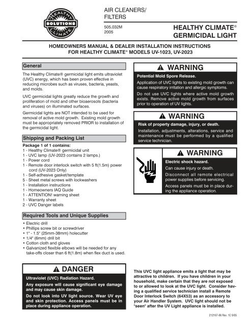
AIR CLEANERS/<br />
FILTERS<br />
505,032M<br />
2005<br />
HEALTHY CLIMATE ®<br />
GERMICIDAL LIGHT<br />
HOMEOWNERS MANUAL & DEALER INSTALLATION INSTRUCTIONS<br />
FOR HEALTHY CLIMATE ® MODELS UV-1023, UV-2023<br />
General<br />
The Healthy Climate® germicidal light emits ultraviolet<br />
(UVC) energy, which has been proven effective in<br />
reducing microbes such as viruses, bacteria, yeasts,<br />
and molds.<br />
UVC germicidal lights greatly reduce the growth and<br />
proliferation of mold and other bioaerosols (bacteria<br />
and viruses) on illuminated surfaces.<br />
<strong>Germicidal</strong> lights are NOT intended to be used for<br />
removal of active mold growth. Existing mold growth<br />
must be appropriately removed PRIOR to installation of<br />
the germicidal light.<br />
Shipping and Packing List<br />
Package 1 of 1 contains:<br />
1 - Healthy Climate® germicidal unit<br />
1 - UVC lamp (UV-2023 contains 2 lamps.)<br />
1 - Power cord<br />
1 - Remote door interlock switch with 5 ft(1.5m) power<br />
cord (UV-2023 Only)<br />
1 - Self-adhesive gasket/template<br />
5 - Sheet metal screws with lockwashers<br />
1 - Installation instructions<br />
1 - Homeowners IAQ Guide<br />
1 - ATTENTION! warning sheet<br />
1 - Warranty sheet<br />
2 - UVC Danger labels<br />
WARNING<br />
Potential Mold Spore Release.<br />
Application of UVC lights to existing mold growth can<br />
cause respiratory irritation and allergic symptoms.<br />
Do not use UVC lights where active mold growth<br />
exists. Remove active mold growth from surfaces<br />
prior to operation of UV lights.<br />
WARNING<br />
Risk of property damage, injury, or death.<br />
Installation, adjustments, alterations, service and<br />
maintenance must be performed by a qualified<br />
service technician.<br />
WARNING<br />
Electric shock hazard.<br />
Can cause injury or death.<br />
Disconnect all remote electrical<br />
power supplies before servicing.<br />
Access panels must be in place during<br />
the appliance operation.<br />
Required Tools and Unique Supplies<br />
• Electric drill<br />
• Phillips screw bit or screwdriver<br />
• 1" - 1.5" (25mm-38mm) holecutter<br />
• 1/4" (6mm) drill bit<br />
• Cotton cloth and gloves<br />
• Galvanized flexible elbows will be needed for any<br />
take-offs closer than 6 ft(1.8m) when flex duct is used.<br />
DANGER<br />
Ultraviolet (UVC) Radiation Hazard.<br />
Any exposure will cause significant eye damage<br />
and may cause skin damage.<br />
Do not look into UV light source. Wear UV eye<br />
and skin protection. Access panels must be in<br />
place during appliance operation.<br />
This UVC light appliance emits a light that may be<br />
attractive to children. If you have children in your<br />
household, make certain that they are not exposed<br />
to or allowed to look at the UVC light. Consider having<br />
a qualified service technician install a Remote<br />
Door Interlock Switch (64X53) as an accessory to<br />
your Air Handler System. UVC light should not be<br />
"seen" after the UV Light appliance is installed.<br />
212167-06 Rev. 1C 9/05
Dimensions/Specifications<br />
DIMENSIONS:<br />
Model UV-1023 - 11" L x 7" W x 2.5" H<br />
(279mm x 178mm x 63mm)<br />
Model UV-2023 - 17" L x 7" W x 2.5" H<br />
(432mm x 178mm x 63mm)<br />
MODEL UV-1023<br />
15.25"<br />
7"<br />
2.5"<br />
All models use 16"(406mm) lamp lengths.<br />
ELECTRICAL:<br />
240 volt, 250V/3 Amp fuse, detachable 6'<br />
(1.8m), three-prong, power cord.<br />
POWER CONSUMPTION:<br />
Model UV-1023 - 55 Watts<br />
Model UV-2023 - 104 Watts<br />
DEVICE OPERATING TEMPERATURE:<br />
45° F - 150° F (7° C - 65° C) Outside of duct.<br />
ACCESSORIES:<br />
Remote Door Interlock Switch (Standard with<br />
UV-2023. Optional for UV-1023. Part No. 64X53.)<br />
LISTINGS:<br />
FIFRA (Federal Insecticide Fungicide Rodentcide Act)<br />
- File No. 73316<br />
ETL, UL and ULC certified to UL STD 1598.<br />
MODEL UV-2023<br />
11"<br />
17.75"<br />
7"<br />
15.25"<br />
10" 17"<br />
2.5"<br />
Specifications subject to change without notice.<br />
17.75"<br />
2
Clearances and Requirements<br />
SELECTING AN INSTALLATION LOCATION<br />
This device has been designed to fit into a wide<br />
variety of locations. Choose a location with<br />
enough clearance (see Fig. 1) to allow the UVC<br />
lamp to be removed and replaced easily. Be<br />
sure to choose a location that is easy to access<br />
for maintenance and that has a 240V power<br />
supply nearby.<br />
Install the device in the return air duct, at the<br />
furnace, near the HVAC coil, or in the supply<br />
air duct. Duct depth must be at least 16"<br />
(406mm) to allow for the lamp length. Ensure<br />
no plastic parts or wire insulation are exposed<br />
to UVC light. Do not install where light can<br />
be seen after installation.<br />
18"(457mm)<br />
clearance.<br />
SPECIAL INSTALLATION NOTES:<br />
●<br />
Do not install in closet return applications.<br />
●<br />
●<br />
●<br />
Do not install in rooftop/outdoor applications.<br />
Do not expose wiring or plastic parts to UVC light.<br />
Do not install device with vents facing down.<br />
●<br />
Do not install device beneath a humidifier or<br />
source of water.<br />
The Healthy Climate® germicidal light must<br />
be installed a minimum of 6 ft(1.8m) away<br />
from plastic materials: filter material, cooling<br />
drain pans, flexible duct, etc., which are in<br />
direct line of sight .<br />
Flexible duct installation with less than 6 ft(1.8m)<br />
clearance between the light and the flex duct<br />
must have a 90 degree metal elbow installed to<br />
protect the duct from direct UVC light exposure.<br />
If the plastic is not in direct line of sight, a minimum<br />
of 3 ft(.9m) is required.<br />
If space limitation prevents the installation<br />
from meeting the above requirements, all plastic<br />
material, cooling drain pans, etc., must be<br />
protected from direct UVC light using aluminum<br />
foil tape.<br />
Fig. 1 Install the device near a cooling coil to reduce mold<br />
and bacteria in the coil fins, drain pans, and surrounding<br />
surfaces.<br />
WARNING<br />
Potential Risk of Fire.<br />
Dust, lint and other debris may cause fire if allowed<br />
to come in contact with illuminated UVC lamp.<br />
Remove any dust, lint or other debris from lamps and<br />
surrounding duct system.<br />
WARNING<br />
Fixture Overheating Risk.<br />
Improper installation may cause<br />
fixture to overheat and will violate<br />
ETL and UL1598 classification.<br />
Do not install appliance with vent<br />
holes facing downward.<br />
CAUTION<br />
Potential Risk of Degradation of Materials.<br />
UVC light may damage plastics and rubber materials.<br />
May cause fabric discoloration.<br />
Avoid UVC light exposure to plastic drain pans, wire<br />
insulation, flex duct or other plastic/rubber components.<br />
3
Installation<br />
INSTALLING THE DEVICE (Fig. 2)<br />
Draw a level line positioned where the top of<br />
the device is to be located. Align the top of the<br />
self-adhesive gasket to the duct. Use the gasket<br />
as a template for drilling the viewport and<br />
lamp holes. Two lamp holes are required for<br />
Model UV-2023. Use a drill bit or holecutter to<br />
make the 1"(25mm) lamp hole(s) required. Use<br />
a 1/4"(6mm) drill bit for drilling the viewport hole.<br />
Remove the cover of the device and attach the<br />
base to the gasket and duct using included<br />
sheet metal screws. For installations on ductboard<br />
use appropriate mounting method.<br />
Lamp and viewport hole<br />
drilling locations for<br />
Model UV-1023.<br />
Self-adhesive<br />
gasket/template.<br />
INSTALLING THE LAMP(s) (Fig. 3)<br />
Once the base has been installed, insert the<br />
lamp and slide the retaining bracket over the<br />
the retaining lip of the lamp. The lamp seals<br />
against the base of the unit with an o-ring<br />
which prevents air leaks.<br />
The slide bracket is tightened with two knurled<br />
nuts. Tighten each nut until the lamp is<br />
securely fastened.<br />
Note: Do not damage wires on outside of<br />
lamp(s) during installation.<br />
Be sure bracket<br />
slips over the<br />
retaining lip of the<br />
lamp.<br />
Fig. 3 Insert lamp and fasten with retaining bracket.<br />
Lamp and viewport hole<br />
drilling locations for<br />
Model UV-2023.<br />
CAUTION<br />
Sharp Edges Hazard.<br />
Equipment sharp edges can cause injuries.<br />
Use protective gloves when grasping equipment edges.<br />
CAUTION<br />
Lamp(s) Contain Mercury.<br />
Ingestion or contact with mercury or mercury vapor<br />
is hazardous to your health.<br />
Take care when handling lamps. If lamp is broken, avoid<br />
contact with mercury.<br />
Fig. 2 Attach self-adhesive gasket to the duct, drill required lamp<br />
and viewport holes, and secure device to the duct using included<br />
sheet metal screws.<br />
NOTICE<br />
Clean lamps prior to installation using a cotton<br />
cloth to remove dirt and fingerprints.<br />
Failure to clean lamp(s) could shorten the lamp(s) lifespan.<br />
4
Installation<br />
HARNESS CONNECTION (Fig. 4)<br />
After the lamp has been installed, attach the wiring harness.<br />
Firmly push the harness connector onto the contacts<br />
of the lamp. If the connector does not go on easily,<br />
check the alignment of the lamp pins and the hole<br />
pattern. Note: The connector pattern is not symmetrical.<br />
If the connector does not attach easily, rotate it<br />
90 degrees and try again.<br />
Attach and close the cover to complete the installation.<br />
The device is now ready to be connected to 240V<br />
power and switched on. Verify operation by looking<br />
through the viewport. The lamp should be radiating a<br />
bright blue light. Do not attempt to view the lamp<br />
directly.<br />
If the connector<br />
does not attach<br />
easily, rotate 90°<br />
and try again.<br />
INSTALL REMOTE DOOR INTERLOCK SWITCH<br />
(Standard with UV-2023. Optional for UV-1023. Part No.<br />
64X53.)<br />
Mount the remote door interlock switch so that power to<br />
the device is automatically disconnected anytime the air<br />
handler access panel is opened.<br />
1. Remove cap as shown in Fig. 5.<br />
2. Insert remote door interlock switch wire through hole.<br />
Secure wire with strain relief that is provided with the<br />
door interlock switch kit. Install male and female connector<br />
to remote door interlock switch wires and connect<br />
to UVC lamp.<br />
3. Mount remote door interlock switch and actuator to<br />
access panel opening.<br />
4. Check operation. Device should turn off when access<br />
panel is opened.<br />
Note: Remote door interlock switch includes 5 ft(1.5m) 240V<br />
power cord with custom connectors. If device is installed<br />
more than 5 ft(1.5m) away from remote door interlock switch,<br />
field wiring will be required in accordance with national and<br />
local codes.<br />
Connect remote<br />
door interlock leads.<br />
Strain relief.<br />
Fig. 4 Attach connector to lamp.<br />
DANGER<br />
Ultraviolet (UVC) Radiation Hazard.<br />
Any exposure will cause significant eye damage<br />
and may cause skin damage.<br />
Do not look into UV light source. Wear UV eye<br />
and skin protection. Access panels must be in<br />
place during appliance operation.<br />
WARNING<br />
Electrical Safety Hazard.<br />
Can cause injury or death.<br />
Do not alter power cord. Any alteration is a violation of<br />
ETL and UL listing and will void the <strong>Lennox</strong> warranty.<br />
5<br />
Remove cap.<br />
Fig. 5 Remote door interlock switch installation.<br />
DANGER LABEL APPLICATION<br />
Install UVC Danger label to air handler access<br />
panel so it is clearly visible. Install the additional<br />
Danger label near location of potential exposure, if<br />
necessary.<br />
Note: In areas where other<br />
Danger labels cannot be<br />
seen clearly and if exposure<br />
to the UVC light is possible<br />
in any other situation (e.g.<br />
when duct panel is<br />
removed), the additional<br />
enclosed Danger label must<br />
be installed in a visible location<br />
near the site where the<br />
exposure may occur.<br />
Mount remote door<br />
interlock to air handler<br />
access panel.<br />
DANGER<br />
Ultraviolet (UVC) Radiation Hazard.<br />
Any exposure will cause significant eye damage<br />
and may cause skin damage.<br />
Do not look into UV light source. Wear UV eye and<br />
skin protection. Access panels must be in place<br />
during appliance operation. Disconnect Power<br />
Cord from UV Light appliance before servicing the<br />
UV Light, the Air Handling Equipment or Duct<br />
System.<br />
212790-00 Rev. 1A 7/03<br />
Fig. 6 Example of the Danger label.
Installation<br />
Operation<br />
Model UV-1023 Internal Wiring<br />
For optimal performance, continuous operation of<br />
the UVC germicidal lamp and the air handler blower<br />
is recommended. IF continuous operation of<br />
the air handler is NOT selected, the UVC germicidal<br />
lamp CAN be operated continuously.<br />
Continuous operation of the air handler motor and<br />
UVC germicidal lamp allows maximum exposure<br />
of airborne bioaerosols to the UVC light. This also<br />
promotes maximum filtration of the air and prevention<br />
of thermal stratification (hot at the ceiling, cool<br />
on the floor).<br />
Model UV-2023 Internal Wiring<br />
6
Maintenance<br />
For all maintenance, contact a qualified HVAC<br />
technician.<br />
IF THE LAMP DOES NOT ILLUMINATE<br />
1. Check power cord for the presence of 240V.<br />
2. Turn off power and remove<br />
access cover.<br />
3. Check 3A fuse for conductivity.<br />
Replace fuse if necessary and<br />
determine the cause of the failure.<br />
4. Check and ensure that the lamp<br />
connector is securely attached<br />
to the lamp.<br />
5. Unplug the connector to the<br />
lamp. Check for resistance<br />
across each narrow spaced pair<br />
of lamp contact pins. Replace<br />
the lamp if an open circuit is<br />
found.<br />
6. If steps 1 through 5 pass inspection then the ballast<br />
may be at fault. Replace the ballast.<br />
LAMP REPLACEMENT(Annually)<br />
The lamp should be replaced annually even if it<br />
appears to be operating normally. UVC energy<br />
production diminishes over time.<br />
1. Obtain the correct replacement lamp for your<br />
Healthy Climate® model.<br />
2. Disconnect power to the device.<br />
3. Open the cover of the device. Allow lamp to<br />
cool 10 minutes before touching.<br />
4. Disconnect the lamp connector.<br />
5. Unscrew the two knurled knobs of the lamp<br />
retaining bracket and slide the bracket away<br />
from the lamp retaining lip.<br />
6. Carefully remove the lamp and replace it with<br />
the new lamp. Be sure to clean the lamp of dust<br />
and fingerprints prior to installation. See page 4.<br />
DANGER<br />
Resistance Tester<br />
Test across each<br />
narrow spaced<br />
pin pair.<br />
Lamp<br />
Ultraviolet (UVC) Radiation Hazard.<br />
Any exposure will cause significant eye damage<br />
and may cause skin damage.<br />
Do not look into UV light source. Wear UV eye<br />
and skin protection. Access panels must be in<br />
place during appliance operation.<br />
7<br />
LAMP REPLACEMENT(cont'd)<br />
7. Slide the retaining bracket back in place and<br />
tighten knurled knobs.<br />
8. Reconnect lamp connector.<br />
9. Close the cover of the device and reconnect<br />
power.<br />
10. Use the viewport to verify operation.<br />
FUSE REPLACEMENT<br />
1. Unscrew the knob marked "Fuse" and remove fuse.<br />
2. Install new fuse and screw knob back in place.<br />
Use a 250V/3 Amp fuse (1.25") only.<br />
LAMP DISPOSAL<br />
Hg-LAMP CONTAINS MERCURY.<br />
Manage in accord with disposal laws.<br />
Refer to www.lamprecycle.org or call 1-800-9-LENNOX.<br />
Personal Burn Hazard.<br />
Personal injury may result from hot lamps.<br />
During replacement, allow lamp to cool for 10 minutes<br />
before removing lamp from fixture.<br />
Lamp(s) Contain Mercury.<br />
Ingestion or contact with mercury or mercury vapor<br />
is hazardous to your health.<br />
Take care when handling lamps. If lamp is broken, avoid<br />
contact with mercury.<br />
PROPER CLEAN-UP TECHNIQUE IN CASE OF<br />
LAMP BREAKAGE<br />
●<br />
●<br />
●<br />
WARNING<br />
WARNING<br />
Potential Risk of Fire.<br />
Dust, lint and other debris may cause fire if allowed<br />
to come in contact with illuminated UVC lamp.<br />
Remove any dust, lint or other debris from lamps and<br />
surrounding duct system.<br />
CAUTION<br />
Wear protective gloves, eyewear and mask.<br />
Sweep the broken glass and debris into a plastic<br />
bag, seal the bag, and dispose of properly.<br />
Contact your local waste management office for<br />
proper disposal.<br />
Do not use a vacuum cleaner. Do not incinerate.
Replacement Parts<br />
No. Description UV-1023 UV-2023<br />
1 Base Gasket/Template 64X42 64X64<br />
2 Lighted On/Off Switch 91X46 91X46<br />
3 Ballast 64X62 64X62<br />
4 Cover Interlock Switch 64X45 64X45<br />
5 Fuseholder 64X48 64X48<br />
6 Fuse 64X49 64X49<br />
Replacement Parts Not Illustrated<br />
Complete Unit w/Lamp(s) X4574 X4582<br />
UVC Replacement Lamp 64X56 64X56<br />
Lamp O-Ring 64X41 64X41<br />
Cover with Label X1932 X1934<br />
Power Cord 91X44 91X44<br />
Remote Door Interlock Switch 64X53 64X53<br />
1 Model UV-2023 requires 2 replacement lamps.<br />
1<br />
Contact your local <strong>Lennox</strong> dealer to order replacement parts. For the <strong>Lennox</strong> dealer nearest you, dial 1-800-9-<strong>Lennox</strong>. Visit us at http://www.<strong>Lennox</strong>.com<br />
2<br />
3<br />
4<br />
5<br />
6<br />
1<br />
FUSE<br />
8
Installation<br />
CHECKLIST FOR COMPLETE INSTALLATION AND SAFETY ITEMS:<br />
All items were included in the shipping box and have been installed (see Shipping and<br />
Packing List).<br />
Danger label installed on door to air handling unit. (See Fig. 6)<br />
Additional Danger label installed, if necessary. (See Fig. 6)<br />
Note: If exposure to the UVC light is possible in any other situation (e.g. when duct panel is<br />
removed), the additional enclosed Danger label must be installed in a visible location near<br />
the site where the exposure may occur.<br />
Turn off room lights while the UVC germicidal light is operating and the access panels are in<br />
place. Make sure that blue light IS NOT visible through supply or return air grilles, holes in<br />
ducts, leaks around access panels, etc.) If blue light is visible, leaks around doors or panels<br />
must be sealed or UVC light must be repositioned so that no light is visible. If it is not possible<br />
to completely avoid exposure to UVC light, device must be removed.<br />
Explained to customer danger of viewing UVC germicidal light. “UVC light is like looking at<br />
the sun, you should not look at the sun and you MUST NOT look at the UVC light. Looking<br />
at the blue light can result in significant eye damage and exposure to it can result in skin<br />
damage. This UVC light appliance emits a light that may be attractive to children. If you<br />
have children in your household, make certain that they are not exposed to or allowed to<br />
look at the UVC light. Consider having a qualified service technician install a Remote Door<br />
Interlock Switch (64X53) as an accessory to your Air Handler System. UVC light should not<br />
be "seen" after the UV Light appliance is installed.”<br />
Checklist has been filled out and left with homeowner.<br />
All instructions and safety instructions have been followed and the<br />
checklist is completed.<br />
Installation Technician Signature:<br />
Date:<br />
Customer Signature:<br />
Date:<br />
This copy to be retained by customer.<br />
9
Installation<br />
CHECKLIST FOR COMPLETE INSTALLATION AND SAFETY ITEMS:<br />
All items were included in the shipping box and have been installed (see Shipping and<br />
Packing List).<br />
Danger label installed on door to air handling unit. (See Fig. 6)<br />
Additional Danger label installed, if necessary. (See Fig. 6)<br />
Note: If exposure to the UVC light is possible in any other situation (e.g. when duct panel is<br />
removed), the additional enclosed Danger label must be installed in a visible location near<br />
the site where the exposure may occur.<br />
Turn off room lights while the UVC germicidal light is operating and the access panels are in<br />
place. Make sure that blue light IS NOT visible through supply or return air grilles, holes in<br />
ducts, leaks around access panels, etc.) If blue light is visible, leaks around doors or panels<br />
must be sealed or UVC light must be repositioned so that no light is visible. If it is not possible<br />
to completely avoid exposure to UVC light, device must be removed.<br />
Explained to customer danger of viewing UVC germicidal light. “UVC light is like looking at<br />
the sun, you should not look at the sun and you MUST NOT look at the UVC light. Looking<br />
at the blue light can result in significant eye damage and exposure to it can result in skin<br />
damage. This UVC light appliance emits a light that may be attractive to children. If you<br />
have children in your household, make certain that they are not exposed to or allowed to<br />
look at the UVC light. Consider having a qualified service technician install a Remote Door<br />
Interlock Switch (64X53) as an accessory to your Air Handler System. UVC light should not<br />
be "seen" after the UV Light appliance is installed.”<br />
Checklist has been filled out and left with homeowner.<br />
All instructions and safety instructions have been followed and the<br />
checklist is completed.<br />
Installation Technician Signature:<br />
Date:<br />
Customer Signature:<br />
Date:<br />
This copy to be retained by installing dealer.<br />
10


