

ELO183B Oil Furnace Installation Manual - Lennox
ELO183B Oil Furnace Installation Manual - Lennox
ELO183B Oil Furnace Installation Manual - Lennox

Create successful ePaper yourself
Turn your PDF publications into a flip-book with our unique Google optimized e-Paper software.
NOTE − If vent pipe needs to exit from side of cabinet,<br />
use the pilot hole (located on either side of the unit) to<br />
cut a 6" (152 mm) round hole. Attach finishing plate<br />
(provided) with four sheet metal screws to cover rough<br />
edges.<br />
Removal of Unit from Common Venting System<br />
In the event that an existing furnace is removed from a<br />
venting system commonly run with separate appliances,<br />
the venting system is likely to be too large to properly vent<br />
the remaining attached appliances. The following test<br />
should be conducted while each appliance is in operation<br />
and the other appliances not in operation remain connected<br />
to the common venting system. If venting system<br />
has been installed improperly, the system must be corrected<br />
as outlined in the previous section.<br />
1 − Seal any unused openings in the common venting<br />
system.<br />
2 − Visually inspect venting system for proper size and<br />
horizontal pitch and determine there is no blockage or<br />
restriction, leakage, corrosion or other deficiencies<br />
which could cause an unsafe condition.<br />
3 − Insofar as is practical, close all building doors and windows<br />
and all doors between the space in which the appliances<br />
remaining connected to the common venting<br />
system are located and other spaces of the building.<br />
Turn on clothes dryers and any appliances not connected<br />
to the common venting system. Turn on any<br />
exhaust fans, such as range hoods and bathroom exhausts,<br />
so they will operate at maximum speed. Do not<br />
operate a summer exhaust fan. Close fireplace dampers.<br />
4 − Following the lighting instruction on the unit, place the<br />
appliance being inspected in operation. Adjust thermostat<br />
so appliance will operate continuously.<br />
5 − Test for spillage using a draft gauge.<br />
6 − After it has been determined that each appliance remaining<br />
connected to the common venting system<br />
properly vents when tested as outlined above, return<br />
doors, windows, exhaust fans, fireplace dampers and<br />
any other fuel burning appliance to its previous condition<br />
of use.<br />
7 − If improper venting is observed during any of the<br />
above tests, the common venting system must be corrected.<br />
Flue Connections<br />
IMPORTANT<br />
When flue pipe is installed at less than minimum<br />
clearance listed in table 2, radiation shields must be<br />
installed. See 11.<br />
For front flue models, the enclosed exhaust pipe ring may<br />
be used for pipe to exit the left or right side of cabinet. Center<br />
line marks are provided in cabinet.<br />
Use 24 gauge or heavier galvanized smoke pipe and fittings<br />
to connect furnace to vent. Connect flue pipe to chimney<br />
using the least number of elbows and angles possible.<br />
Flue pipe or vent connector must be inserted into the chimney<br />
so that it is flush with the inside of the vent liner. No reduction<br />
in diameter of flue pipe is acceptable. It is best to<br />
have flue pipe as short and direct as possible. Where two or<br />
more appliances vent into a common flue, the area of the<br />
common flue should be at least equal to the area of the largest<br />
flue or vent connector, plus 50% of the area of any additional<br />
flues or vent connectors. Install the barometric draft<br />
control (provided) and flue pipe according to instructions<br />
packed with control.<br />
Inspect flue pipe annually. Clean soot or ash from flue pipe,<br />
if necessary. If pipe is rusted, replace.<br />
combustible<br />
material<br />
unit<br />
cabinet<br />
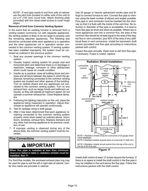
Radiation Shield <strong>Installation</strong><br />
noncombustible<br />
spacers<br />
ÉÉÉÉÉÉÉÉ<br />
ÉÉÉÉÉÉÉÉ<br />
ÉÉÉÉÉÉÉÉ<br />
ÉÉÉÉÉÉÉÉ<br />
ÉÉÉÉÉÉÉÉ<br />
ÉÉÉÉÉÉÉÉ<br />
A<br />
see note 2<br />
<strong>ELO183B</strong> unit<br />
(top)<br />
radiation<br />
shields<br />
ÉÉÉÉÉÉÉÉ<br />
ÉÉÉÉÉÉÉÉ<br />
ÉÉÉÉÉÉÉÉ<br />
ÉÉÉÉÉÉÉÉ<br />
ÉÉÉÉÉÉÉÉ<br />
ÉÉÉÉÉÉÉÉ<br />
flue<br />
pipe<br />
ÉÉÉÉÉÉÉÉ<br />
ÉÉÉÉÉÉÉÉ<br />
ÉÉÉÉÉÉÉÉ<br />
ÉÉÉÉÉÉÉÉ<br />
ÉÉÉÉÉÉÉÉ<br />
Figure 11<br />
A<br />
radiation shields<br />
(see note 1)<br />
<strong>ELO183B</strong> unit<br />
(front)<br />
1" (25 mm)<br />
min<br />
12" (305 mm)<br />
min<br />
7" (178 mm)<br />
min<br />
B<br />
see note 3<br />
NOTE 1−Radiation shields must be constructed of 24 gauge sheet<br />
metal minimum.<br />
NOTE 2−Radiation shields required when A is less than 9" (229 mm).<br />
NOTE 3−Radiation shields should extend from the top of the unit to<br />
the top of the flue pipe.<br />
Install draft control at least 12 inches beyond the furnace. If<br />
there is no space to install the draft control in the flue pipe it<br />
may be installed in the vent above the flue pipe. Follow the<br />
instructions packed with the draft control.<br />
Page 10


