

GWB8-IE Boiler Installation Manual - Lennox
GWB8-IE Boiler Installation Manual - Lennox
GWB8-IE Boiler Installation Manual - Lennox

You also want an ePaper? Increase the reach of your titles
YUMPU automatically turns print PDFs into web optimized ePapers that Google loves.
OPTIONAL HORIZONTAL VENTING INSTRUCTION<br />
Horizontal venting with a power venter is an alternate<br />
method of sidewall venting. This boiler is CSA listed for<br />
sidewall venting with standard single wall galvanized or<br />
Type B vent pipe when using the following power venter<br />
kits, which were specifically sized for these boilers:<br />
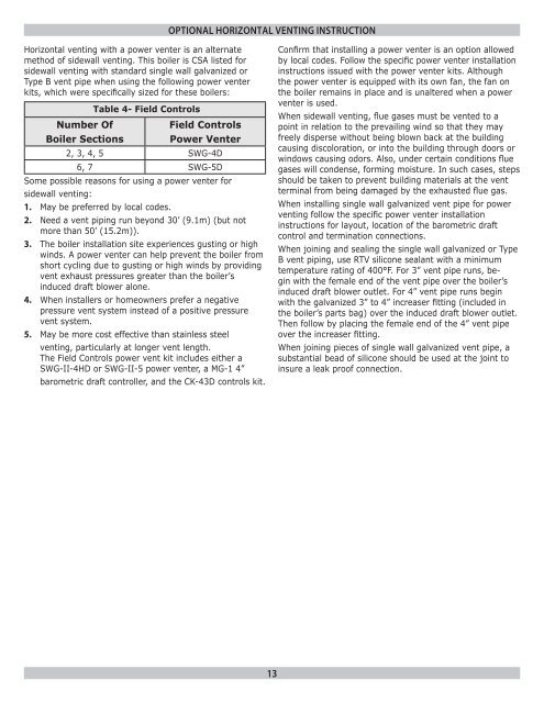
Table 4- Field Controls<br />
Number Of<br />
Field Controls<br />
<strong>Boiler</strong> Sections Power Venter<br />
2, 3, 4, 5 SWG-4D<br />
6, 7 SWG-5D<br />
Some possible reasons for using a power venter for<br />
sidewall venting:<br />
1. May be preferred by local codes.<br />
2. Need a vent piping run beyond 30’ (9.1m) (but not<br />
more than 50’ (15.2m)).<br />
3. The boiler installation site experiences gusting or high<br />
winds. A power venter can help prevent the boiler from<br />
short cycling due to gusting or high winds by providing<br />
vent exhaust pressures greater than the boiler’s<br />
induced draft blower alone.<br />
4. When installers or homeowners prefer a negative<br />
pressure vent system instead of a positive pressure<br />
vent system.<br />
5. May be more cost effective than stainless steel<br />
venting, particularly at longer vent length.<br />
The Field Controls power vent kit includes either a<br />
SWG-II-4HD or SWG-II-5 power venter, a MG-1 4”<br />
barometric draft controller, and the CK-43D controls kit.<br />
Confirm that installing a power venter is an option allowed<br />
by local codes. Follow the specific power venter installation<br />
instructions issued with the power venter kits. Although<br />
the power venter is equipped with its own fan, the fan on<br />
the boiler remains in place and is unaltered when a power<br />
venter is used.<br />
When sidewall venting, flue gases must be vented to a<br />
point in relation to the prevailing wind so that they may<br />
freely disperse without being blown back at the building<br />
causing discoloration, or into the building through doors or<br />
windows causing odors. Also, under certain conditions flue<br />
gases will condense, forming moisture. In such cases, steps<br />
should be taken to prevent building materials at the vent<br />
terminal from being damaged by the exhausted flue gas.<br />
When installing single wall galvanized vent pipe for power<br />
venting follow the specific power venter installation<br />
instructions for layout, location of the barometric draft<br />
control and termination connections.<br />
When joining and sealing the single wall galvanized or Type<br />
B vent piping, use RTV silicone sealant with a minimum<br />
temperature rating of 400°F. For 3” vent pipe runs, begin<br />
with the female end of the vent pipe over the boiler’s<br />
induced draft blower outlet. For 4” vent pipe runs begin<br />
with the galvanized 3” to 4” increaser fitting (included in<br />
the boiler’s parts bag) over the induced draft blower outlet.<br />
Then follow by placing the female end of the 4” vent pipe<br />
over the increaser fitting.<br />
When joining pieces of single wall galvanized vent pipe, a<br />
substantial bead of silicone should be used at the joint to<br />
insure a leak proof connection.<br />
13


