

GWB8-IE Boiler Installation Manual - Lennox
GWB8-IE Boiler Installation Manual - Lennox
GWB8-IE Boiler Installation Manual - Lennox

Create successful ePaper yourself
Turn your PDF publications into a flip-book with our unique Google optimized e-Paper software.
INSTALLATION SYSTEM PIPING<br />
! WARNING<br />
Burn or Scald Hazard. Discharge line shall be installed to relief valve outlet connection to avoid burns,<br />
scalding, or water damage due to discharge of steam and/or hot water during operation.<br />
Discharge line shall:<br />
• connect to relief valve outlet and piped down to safe point of disposal. Check local codes for maximum<br />
distance from floor or allowable safe point of discharge.<br />
• be of pipe size equal to or greater than that of the relief valve outlet over the entire length of discharge<br />
line;<br />
• have no intervening shutoff valve between safety relief valve and discharge to atmosphere (do not plug or<br />
place any obstruction in discharge line.<br />
• terminate freely to atmosphere where any discharge will be clearly visible and at no risk of freezing;<br />
• allow complete drainage of the valve and the discharge line;<br />
• be independently supported and securely anchored to avoid applied stress on the relief valve;<br />
• be as short and straight as possible;<br />
• terminate with plain end (not threaded);<br />
• be constructed of material suitable for exposure to temperatures of 375° F; or greater.<br />
Refer to local codes and appropriate ANSI/ASME <strong>Boiler</strong> and Pressure Vessel Code, Section IV, or <strong>Boiler</strong>,<br />
Pressure Vessel and Pressure Piping Code, CSA B51 for additional installation requirements.<br />
1. Refer to local codes and appropriate ASME <strong>Boiler</strong><br />
and Pressure Vessel Code for additional installation<br />
requirements.<br />
2. Install relief valve on 3/4” pipe nipple in tapped boiler<br />
opening.<br />
A. Pipe discharge line following guidelines in preceding<br />
Warning. See Figure 2.<br />
B. Discharge line pipe size shall be equal or greater<br />
than that of relief valve outlet over entire length<br />
of discharge line with no intervening shutoff valve<br />
between safety relief valve and discharge to<br />
atmosphere.<br />
C. Discharge line shall terminate with plain end to<br />
atmosphere where any discharge will be clearly<br />
visible and is at no risk of freezing.<br />
D. Discharge line shall be independently supported to<br />
avoid applied stress on relief valve.<br />
E. <strong>Installation</strong> shall allow complete drainage of relief<br />
valve and discharge line.<br />
3. Install Drain Valve on lower left side of boiler as<br />
marked.<br />
4. Install Temperature and Pressure Gauge into ¼”<br />
bushing threaded in tee furnished with supply piping.<br />
See Figures 3 and 4.<br />
5. Connect Supply and Return Lines to boiler. Figure 3 &<br />
4. Connections may require certain additional fittings<br />
and parts.<br />
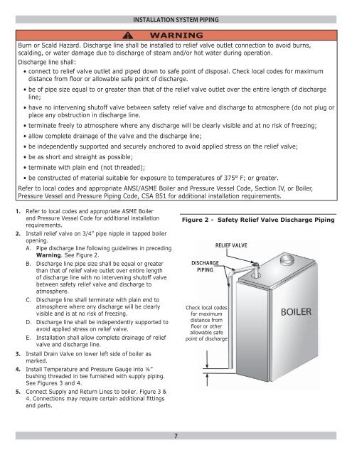
Figure 2 - Safety Relief Valve Discharge Piping<br />
DISCHARGE<br />
PIPING<br />
Check local codes<br />
for maximum<br />
distance from<br />
floor or other<br />
allowable safe<br />
point of discharge<br />
REL<strong>IE</strong>F VALVE<br />
7


