Super Comet Pressure Blast & Vacuum System - Clemco Industries ...
Super Comet Pressure Blast & Vacuum System - Clemco Industries ...
Super Comet Pressure Blast & Vacuum System - Clemco Industries ...

You also want an ePaper? Increase the reach of your titles
YUMPU automatically turns print PDFs into web optimized ePapers that Google loves.
SUPER COMET<br />
PRESSURE BLAST and VACUUM SYSTEM<br />
O. M. 23437<br />
MC FILE NUMBER: 2099-0300<br />
DATE OF ISSUE: 02/20/02<br />
REVISION:<br />
NOTICE TO PURCHASERS AND USERS OF OUR PRODUCTS<br />
AND THIS INFORMATIONAL MATERIAL<br />
The products described in this material, and the information<br />
relating to those products, is intended for knowledgeable,<br />
experienced users of abrasive blasting equipment.<br />
No representation is intended or made as to the suitability of the<br />
products described herein for any particular purpose of<br />
application. No representations are intended or made as to the<br />
efficiency, production rate, or the useful life of the products<br />
described herein. Any estimate regarding production rates or<br />
production finishes are the responsibility of the user and must be<br />
derived solely from the user’s experience and expertise, and must<br />
not be based on information in this material.<br />
The products described in this material may be combined by the<br />
user in a variety of ways for purposes determined solely by the<br />
user. No representations are intended or made as to the suitability<br />
or engineering balance of the combination of products determined<br />
by the user in his selection, nor as to the compliance with<br />
regulations or standard practice of such combinations of<br />
components or products.<br />
© 2004 CLEMCO INDUSTRIES CORP.<br />
One Cable Car Dr.<br />
Washington, MO 63090<br />
Phone (636) 239-4300<br />
FAX (800) 726-7559<br />
Email: info@clemcoindustries.com<br />
www.clemcoindustries.com<br />
®<br />
It is the responsibility of the knowledgeable, experienced users of<br />
the products mentioned in this material to familiarize themselves<br />
with the appropriate laws, regulations and safe practices that<br />
apply to these products, equipment that is connected to these<br />
products, and materials that may be used with these products.<br />
It is the responsibility of the user to insure that proper training of<br />
operators has been performed and a safe work environment is<br />
provided.<br />
Our company is proud to provide a variety of products to the<br />
abrasive blasting industry, and we have confidence that the<br />
professionals in our industry will utilize their knowledge and<br />
expertise in the safe efficient use of these products.
SUPER COMET PRESSURE BLAST and RECOVERY MACHINE Page 1<br />
1.0 INTRODUCTION<br />
1.1 Scope of manual<br />
1.1.1 These instructions cover the set-up, operation,<br />
maintenance, troubleshooting, and replacement parts<br />
for the <strong>Super</strong>-<strong>Comet</strong> blast and recovery machine.<br />
1.1.2 These instructions also contain important<br />
information required for safe operation. All blast<br />
operator(s) must be trained in the safe operation of the<br />
blast machine system and all blasting accessories. The<br />
operators and all personnel associated with the abrasive<br />
blasting process must know about the hazards<br />
associated with abrasive blasting. Before using the<br />
machine, all personnel associated with the blast<br />
machine operation must read this entire manual,<br />
including the orange cover, and all accessory manuals.<br />
1.2 Safety Alerts<br />
1.2.1 <strong>Clemco</strong> uses safety alert signal words, based on<br />
ANSI Z535.4-1998, to alert the user of a potentially<br />
hazardous situation that may be encountered while<br />
operating this equipment. ANSI's definitions of the signal<br />
words are as follows:<br />
This is the safety alert symbol. It is used<br />
to alert the user of this equipment of<br />
potential personal injury hazards.<br />
Obey all safety messages that follow this symbol to<br />
avoid possible injury or death.<br />
CAUTION<br />
Caution used without the safety alert symbol<br />
indicates a potentially hazardous situation<br />
which, if not avoided, may result in property<br />
damage.<br />
CAUTION<br />
Caution indicates a potentially hazardous<br />
situation which, if not avoided, may result in<br />
minor or moderate injury.<br />
WARNING<br />
Warning indicates a potentially hazardous<br />
situation which, if not avoided, could result in<br />
death or serious injury.<br />
DANGER<br />
Danger indicates an imminently hazardous<br />
situation which, if not avoided, will result in<br />
death or serious injury.<br />
1.3 Components and Theory of Operation<br />
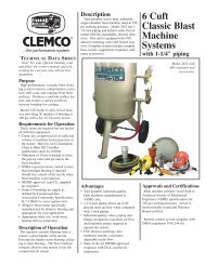
1.3.1 Components, Figure 1<br />
1.3.1.1 The primary components of the <strong>Super</strong>-<strong>Comet</strong> are:<br />
1. <strong>Blast</strong> machine with controls and blast hose<br />
2. <strong>Blast</strong> head assembly with brushes for inside<br />
corner, outside corner and flat surfaces.<br />
3. Reclaimer and recovery hose<br />
4. Dust collector and exhauster<br />
5. Cart<br />
1.3.2 <strong>Blast</strong> Machine<br />
1.3.2.1 The blast machine pressure vessel is<br />
manufactured to American Society of Mechanical<br />
Engineers (ASME) standards, as described in Section<br />
VII, Div. 1, and carry a National Board certification. It is<br />
the owners responsibility to maintain the integrity of the<br />
vessel as may be required by some states. This may<br />
include regular inspection and hydrostatic testing as<br />
described in National Board Inspection Code and<br />
Jurisdictional Regulations and /or Laws.<br />
WARNING<br />
Welding, grinding, or drilling on the blast<br />
machine could weaken the vessel. Compressed<br />
air pressure could cause a weakened vessel to<br />
rupture, resulting in death or serious injury.<br />
Welding, grinding, or drilling on the blast<br />
machine vessel, without a National Board ″R″<br />
stamp voids the ASME and National Board<br />
certification.<br />
1.3.2.2 All welding repairs done on the vessel must be<br />
performed by certified welders, at shops holding a<br />
National Board ″R″ Stamp. Welding performed by any<br />
welder not properly qualified per the ASME Code voids<br />
ASME and National Board certification of the vessel.<br />
1.3.2.3 The vessel is rated for a maximum of 125 psi<br />
(pounds per square inch); do not exceed rated pressure.<br />
WARNING<br />
Excessive air pressure could cause the blast<br />
machine to rupture. To prevent serious injury or<br />
death, do not exceed the rated pressure of the<br />
blast machine vessel.
SUPER COMET PRESSURE BLAST and RECOVERY MACHINE Page 2<br />
Control Cord<br />
To blast head<br />
Exhauster<br />
Reclaimer<br />
<strong>Blast</strong> Machine<br />
115 Volt Plug<br />
Media Metering Valve<br />
Air Filter<br />
Compressed Air Inlet<br />
Exhauster<br />
On-Off Switch<br />
Dust Collector<br />
Tube Filters<br />
Debris Screen<br />
Choke Valve<br />
Finger (blast) Switch<br />
Dust Door<br />
<strong>Blast</strong> Head Assembly<br />
Dust Drawer<br />
Exhaust Muffler<br />
<strong>Vacuum</strong> Recovery Hose<br />
<strong>Blast</strong> Hose<br />
Figure 1<br />
1.3.2.4 OSHA does not require pressure relief valves on<br />
blast machines when air compressors supplying air to<br />
the blast machines are built to ASME (1) specifications<br />
and comply with OSHA (2) regulations. ASME Manual<br />
section VIII, Division 1, UG-125, paragraph A90 (g)<br />
states that pressure relief valves or protective devices<br />
"...need not be installed directly on a pressure vessel<br />
when the source of pressure is external to the vessel<br />
and is under such positive control that the pressure<br />
in the vessel cannot exceed the maximum allowable<br />
working pressure at the operating temperature...".<br />
OSHA regulation 1910.169 refers to the above ASME<br />
code when describing the necessity of pressure relief<br />
valves on compressed air equipment. DO NOT operate<br />
blast machines with air compressors that are not<br />
equipped with properly functioning pressure relief valves.<br />
(1)<br />
American Society of Mechanical Engineers, Boiler and <strong>Pressure</strong><br />
Vessel Code, 1989<br />
(2)<br />
Occupational Safety and Health Administration, 29 CFR 1910,<br />
Subpart M - Compressed Gas and Compressed Air Equipment.<br />
1.3.3 Theory of Operation<br />
1.3.3.1 When the air supply is on, and electrical power<br />
is connected, the blast machine is ready for actuation by<br />
the switch mounted on the blast hose hand grip<br />
assembly. Pressing the finger switch activate the<br />
electrical solenoid, which pneumatically opens the<br />
normally closed main inlet regulator, and closes the<br />
normally open outlet valve. The incoming air pressurizes<br />
the blast machine, and blasting begins. When pressure<br />
on the switch is released, the blast machine<br />
depressurizes, and blasting stops.
SUPER COMET PRESSURE BLAST and RECOVERY MACHINE Page 3<br />
1.3.3.2 During operation the abrasive metering valve,<br />
installed at the bottom of the pressure vessel, meters a<br />
controlled quantity of abrasive into the air stream, The air<br />
and abrasive travels through the blast hose to the blast<br />
gun. <strong>Blast</strong>ing is contained entirely within the hand held<br />
gun assembly. A brush at the end of the assembly,<br />
confines the abrasive and draws in atmospheric air,<br />
sweeping the blast area clean.<br />
1.3.3.3 Spent abrasive and by-products are conveyed<br />
from the blast surface to the reclaimer. At the reclaimer,<br />
the reusable abrasive material drops out of suspension<br />
due to the cyclonic action, passes through a screen and<br />
collects in a hopper located above the blast machine.<br />
1.3.3.4 Air, dust and fine by-products leave the<br />
reclaimer and are drawn through the dust collector. Dust<br />
collects in the cloth filter, and the cleaned air passes<br />
through the exhaust fan and is discharged into the<br />
atmosphere. Dust particles trapped by the filter bags are<br />
removed by a mechanical bag shaking mechanism; dust<br />
released from the bags collects in a pan for disposal.<br />
1.3.3.5 When the operator releases the control switch,<br />
stopping the blast action, the blast machine<br />
depressurizes, and automatically refills with abrasive<br />
collected in the reclaimer hopper.<br />
1.4 Nozzle Options<br />
1.4.1 <strong>Super</strong>-<strong>Comet</strong>s are shipped with a 3/16" orifice<br />
tungsten carbide nozzle. Use an optional boron carbide<br />
nozzle (and tube insert) when blasting with aggressive<br />
abrasive. See Section 8.1.<br />
1.5 Abrasive<br />
1.5.1 <strong>Super</strong>-<strong>Comet</strong>s are designed to utilize most<br />
common recyclable abrasives, between 60 and 280<br />
mesh that are specifically manufactured for blasting.<br />
Suitable abrasive mesh sizes are based on typical<br />
abrasive flow.<br />
1.5.2 Glass Bead: Glass bead No. 6 to 13 may be<br />
used. Most beads are treated to ensure free-flow<br />
operation even with moderately high humidity. Glass<br />
beads subjected to moisture may be reused only after<br />
thorough drying and breaking up of the lumps.<br />
1.5.3 Aluminum Oxide, Silicon Carbide, and<br />
Garnet: Aggressive abrasives such as these may be<br />
used, but consideration must be given to the rapid wear<br />
on all parts of the system (reclaimer, nozzle, or hoses<br />
etc.) which come in contact with the abrasive. Optional<br />
boron nozzles are required when any of these abrasives<br />
are used. See Section 8.1.<br />
1.5.4 Steel: Steel grit or shot is too heavy for the<br />
system to recover. Do not use metallic abrasive.<br />
1.5.5 Sand and Slag: Sand should never be used<br />
because of the respiratory hazards associated with<br />
abrasives containing free silica. Slags are not<br />
recommended because they rapidly break down.<br />
2.0 SET-UP<br />
2.1 Compressed Air Requirements<br />
2.1.1 Minimum air supply requirements are 70 cfm (45<br />
cfm when nozzle is new, 70 cfm when nozzle is worn) at<br />
80 psi.<br />
2.1.2 The air supply line from the compressor to the<br />
blast machine inlet should have a minimum ID of 3/4″.<br />
2.1.3 Install an air supply hose fitting to air filter, that is<br />
compatible with the compressed-air supply hose.<br />
2.1.4 Install an isolation valve at the air source to<br />
enable depressurization for service, and connect an air<br />
line from the air source to the air filter inlet located at the<br />
blast machine inlet.<br />
WARNING<br />
If twist-on type air hose couplings are used,<br />
they must be secured by safety lock pins or<br />
wires to prevent accidental disconnection while<br />
under pressure. Hose disconnection while<br />
under pressure could cause serious injury.<br />
2.1.5 The air filter removes condensed water from the<br />
compressed air. Its use is especially important in areas<br />
of high humidity, or when fine-mesh abrasive is used.<br />
Moisture causes abrasive to clot and inhibits free flow. If<br />
moisture problems persist, an air dryer may be required.<br />
2.2 Electrical Requirements<br />
2.2.1 115-VAC, 1-Ph, 60-Hz, with 15 Amps. A power<br />
cord is supplied. No additional wiring is required. SEE<br />
FOLLOWING IMPORTANT WARNING.<br />
WARNING<br />
Do not use electrical adaptors that eliminate the<br />
ground prong on 115 volt plugs. Doing so can<br />
cause electric shock and equipment damage.
SUPER COMET PRESSURE BLAST and RECOVERY MACHINE Page 4<br />
3.0 OPERATION<br />
3.1 Inspection<br />
3.1.1 Make sure the coupling gaskets are in place and<br />
in good condition before connecting the blast hose to the<br />
quick coupling on the blast machine. Use safety lockpins<br />
or safety wire to lock the couplings together, to<br />
prevent accidental separation during blasting.<br />
3.1.2 Make sure that all compressed-air supply hose<br />
connections are secured with safety lock pins and safety<br />
cables to prevent accidental separation or disconnection.<br />
Lock pins and safety cables are listed in Section 8.5.<br />
WARNING<br />
Hose disconnection while under pressure could<br />
cause serious injury or death. Use safety lockpins<br />
and safety cables on all coupling<br />
connections to help prevent hose couplings<br />
from accidental disconnection.<br />
3.1.3 Make sure that all air fittings are secure. Leaks<br />
will cause the system to malfunction.<br />
3.1.4 Check that the choke valve is open (handle in-line<br />
with the piping).<br />
3.1.5 Close the abrasive metering valve. The closed<br />
position for the Sentinel valve is fully right.<br />
3.2 Loading the Machine with Abrasive<br />
3.2.1 Capacity: Abrasive capacity is approximately .5<br />
cu. ft (1/2 cubic foot). The machine is full when abrasive<br />
reaches the level of the pop-up valve. Overfilling will<br />
result in abrasive carryover to the dust collector and<br />
possible blockage in the conveying hose.<br />
3.2.2 Abrasive Loading: With the exhauster off, pour<br />
clean, dry abrasive into the reclaimer hopper through the<br />
reclaimer door.<br />
3.3 Emptying the Machine of Abrasive<br />
3.3.1 When working in environments subject to<br />
extreme temperature changes, or very humid conditions,<br />
condensation may develop inside the machine.<br />
Condensation wets abrasive and causes flow problems.<br />
To prevent this, empty the machine of all abrasive when<br />
shutting down for the day. This will eliminate trouble from<br />
moist abrasive when starting a new day's blasting.<br />
3.3.2 With the blast machine off, turn the blast<br />
pressure down to approximately 40 psi, close the choke<br />
valve and set the abrasive metering valve at full open.<br />
3.3.3 Point the nozzle into a drum or suitable<br />
container, or in the direction the abrasive is to be<br />
disposed.<br />
3.3.4 Hold the hose securely and pressurize the<br />
machine by activating the control switch. Be prepared for<br />
surging, or recoil of the hose, which can be severe.<br />
3.3.5 When the machine is empty, release the control<br />
switch, open the choke valve, and reset the abrasive<br />
metering valve.<br />
3.4 Select Brush<br />
3.4.1 Three containment brushes are supplied: One<br />
for flat surfaces, one for inside corners, and one for<br />
outside corners.<br />
3.4.2 Using the elastic brush retainer, attach the<br />
appropriate brush to the blast head.<br />
3.5 <strong>Blast</strong>ing Operation<br />
CAUTION<br />
All parts to be blasted must be free of oil,<br />
water, and other contaminants. If not clean,<br />
the abrasive may contaminate the blast<br />
surface, and may clog abrasive, resulting in<br />
equipment malfunction.<br />
3.5.1 Operators must wear operator safety equipment.<br />
A NIOSH-approved, supplied-air respirator protects<br />
against inhalation of dust. Heavy gloves and clothing will<br />
help prevent serious injury from the abrasive blast if the<br />
closed brushes are accidentally lifted off the surface.<br />
3.5.2 The machine is ready for operation when<br />
compressed air and electrical power are supplied to the<br />
machine, and the machine contains abrasive.<br />
3.5.3 Adjust the pressure regulator, located on the<br />
blast machine piping, to the required blasting pressure<br />
per Section 4.1.<br />
3.5.4 Start the exhauster by flipping the toggle switch<br />
located on the electrical panel.<br />
3.5.5 Hold the blast head brushes against the surface<br />
to be blasted, depress the finger switch, blasting (air only at<br />
this time) will begin within a couple of seconds. Adjust the<br />
abrasive flow per Section 4.2
SUPER COMET PRESSURE BLAST and RECOVERY MACHINE Page 5<br />
3.5.6 To stop blasting, release the pressure on the<br />
finger switch. Leave the brush against the surface for<br />
several seconds after blasting stops, to ensure that all<br />
abrasive is recovered from the surface.<br />
3.6 Operating Technique<br />
3.6.1 To achieve full abrasive and dust recovery the<br />
brush must be in contact with the surface at all times.<br />
3.6.2 Keep the brush flat against the surface. Keep the<br />
blasting head perpendicular to the surface.<br />
3.6.3 Do not apply excessive pressure that would cause<br />
the brush to bend into the blast stream.<br />
3.6.4 Make straight, even passes over the blast surface.<br />
The blast pattern should barely overlap the pattern from the<br />
previous pass.<br />
3.6.5 When reversing direction, move the gun and brush<br />
in a small radius, allowing the brush bristles to roll evenly.<br />
3.7 Shut-down<br />
3.7.1 After blasting is complete, run the exhauster for<br />
several seconds to clear the hoses.<br />
3.7.2 When shutting down for the day, empty the<br />
machine of abrasive per section 3.3.<br />
3.7.3 Close the compressed-air supply valve.<br />
3.7.4 Drain receiver tank, filters, and water collecting<br />
devices, and bleed the compressed-air supply hose.<br />
3.7.5 Shutdown the compressor.<br />
4.0 ADJUSTMENTS<br />
4.1 <strong>Blast</strong> <strong>Pressure</strong><br />
4.1.1 The blast pressure pilot regulator, located on the<br />
blast machine, enables the user to adjust blasting<br />
pressure to suit the application. The suitable pressure for<br />
most purposes is 80 psi. Lower pressures may be used<br />
for delicate work. In all cases, highest production can be<br />
achieved only when pressure is carefully monitored.<br />
4.1.2 To adjust, unlock the knob, and turn it clockwise<br />
to increase pressure or counter-clockwise to decrease<br />
pressure. <strong>Pressure</strong> will usually drop from closed-line<br />
pressure when blasting is started. Once operating<br />
pressure is set, lock the knob to maintain the setting.<br />
4.2 Abrasive Metering<br />
4.2.1 Abrasive flow is adjusted by the metering valve<br />
located at the bottom of the blast machine. The valve is<br />
closed when the handle is fully right. To adjust, close the<br />
valve and slowly move the handle to the left to increase<br />
abrasive flow. Allow time for the flow to stabilize before<br />
further adjusting. The valve is fully open when the handle<br />
is at the full left position. The correct flow rate will<br />
depend on the type and size of abrasive and blasting<br />
pressure, and can best be determined by experience.<br />
Use as little abrasive as possible to do the job while<br />
maintaining the best cleaning rate.<br />
5.0 PREVENTIVE MAINTENANCE<br />
WARNING<br />
Failure to wear approved respirators and eye<br />
protection when servicing dust-laden areas of<br />
the dust collector, and when emptying the dust<br />
drawer, could result in serious eye irritation and<br />
lung disease or death. Toxicity and health risk<br />
vary with type of abrasive and dust generated<br />
by blasting. The respirator must be approved<br />
for the type of dust generated. Identify all<br />
material being removed by blasting, and obtain<br />
a material safety data sheet for the blast<br />
abrasive.<br />
5.1 Inspection<br />
5.1.1 To avoid unscheduled downtime, establish a<br />
weekly inspection schedule. Inspect all parts subjected<br />
to abrasive contact.<br />
5.1.2 Inspect the blast head assembly, nozzle, and<br />
brushes for wear.<br />
5.1.3 Inspect the blast hose and recovery hose for<br />
wear by squeezing and feeling for soft spots.<br />
5.1.4 Inspect dust collector bag compartment for dust.<br />
Check the dust bags for wear.<br />
5.1.5 Inspect the reclaimer wear plate for wear.<br />
Replace the wear plate before the rubber coating wears<br />
through.
SUPER COMET PRESSURE BLAST and RECOVERY MACHINE Page 6<br />
5.2 Dust Collector<br />
5.2.1 The dust collector uses tubular filters which<br />
collect dust on their inner surfaces. Every two to three<br />
hours while the exhauster is on, clean the filter bags by<br />
opening and closing each door four to six times in<br />
succession. Hand pulls are provided on these two doors<br />
which are located on the dust collector directly above the<br />
dust drawer. Opening and closing the doors momentarily<br />
compresses the filter bag, loosens dust, dropping it into<br />
the dust drawer. During the blasting operation, the<br />
collector doors must be closed tightly.<br />
5.2.2 Empty the dust drawer regularly. Begin by<br />
checking the drawer after every bag cleaning, and adjust<br />
frequency based on usage and breakdown rate of<br />
abrasive. Dump the contents into a suitable disposal<br />
container.<br />
CAUTION<br />
<strong>Blast</strong> media is usually non-toxic, however,<br />
some materials removed by the process may be<br />
toxic. Check with proper authorities for disposal<br />
regulations.<br />
5.3 Debris Screen<br />
5.3.1 The screen is accessible through the reclaimer<br />
door. With the exhauster off, remove the screen and<br />
empty it daily or when loading abrasive. Empty more<br />
often if part blasted causes excessive debris. Do not<br />
operate the machine without the screen in place.<br />
5.4 Air Filter<br />
5.4.1 The blast machine is equipped with a manual<br />
drain air filter. Drain the filter at least once a day, and<br />
more often if an abundance of moisture accumulates.<br />
Moist air inhibits the flow of abrasive. If moisture<br />
continues to be present, a dryer or aftercooler may be<br />
required in the air supply line.<br />
5.5 Changing Abrasive Type<br />
5.5.1 When changing the type of abrasive, make sure<br />
the blast machine, blast hose, recovery hose, and<br />
reclaimer are carefully cleaned, to remove any remaining<br />
abrasive material. If not carefully done the new abrasive<br />
will be contaminated.<br />
6.0 SERVICE MAINTENANCE<br />
WARNING<br />
Failure to wear approved respirators and eye<br />
protection when servicing dust-laden areas of<br />
the dust collector, and when emptying the dust<br />
collector could result in serious eye irritation<br />
and lung disease or death. Toxicity and health<br />
risk vary with type of media and dust generated<br />
by blasting. Identify all material being removed<br />
by blasting, and obtain a material safety data<br />
sheet for the blast media.<br />
6.1 Nozzle<br />
6.1.1 Replace the nozzle when its diameter has<br />
increased by 1/16", or sooner if pressure diminishes<br />
noticeably, or if abrasive escapes from the brush. Make<br />
sure the nozzle gasket is in place before screwing the<br />
nozzle into the nozzle holder.<br />
6.2 Filter Tube Replacement<br />
CAUTION<br />
• Do not bend spring ends tight enough to<br />
cause ends to kink.<br />
• Do not use a sharp instrument to force<br />
spring rings into the opening. This could<br />
damage the filter and seriously impair the<br />
function of the dust collector.<br />
• Install one filter at a time. Check the seating<br />
of the top and bottom spring rings, and that<br />
tube is not twisted, before proceeding to the<br />
next.<br />
6.2.1 Replace damaged filters immediately. Remove<br />
the old filters by pulling the spring rings off the bottom<br />
and top tube plates. Working from the back to the front,<br />
install one filter at a time. To install new filters, form the<br />
end of the spring ringed tubular filter into a shallow "c"<br />
shape, push the filter far enough into the hole of the top<br />
plate to allow one spring ring to snap into place above<br />
the tube plate and the other to snap into place below it.<br />
See the illustration in Figure 2.<br />
6.2.2 The tubular filters are held firmly by a spring ring<br />
above and below the perimeter of the hole in the plate.<br />
The other end of the filter is similarly installed in the<br />
lower plate. The filters fit tight to prevent dust leakage.<br />
To ensure a tight seal, some force may be required by<br />
the installer. Check for proper seating at both ends, and<br />
remove any twist before proceeding to the next filter.
SUPER COMET PRESSURE BLAST and RECOVERY MACHINE Page 7<br />
One ring above tube plate<br />
Top Tube Plate<br />
One ring below tube plate<br />
6.3 Brushes<br />
Spring Ring<br />
Bottom Tube Plate<br />
Spring Ring<br />
Figure 2<br />
6.3.1 To avoid unscheduled down-time, keep spare<br />
brushes on-hand. Replace brushes at the first sign of<br />
deterioration. Worn brush will cause abrasive escaping<br />
at the blast surface.<br />
6.4 Reclaimer Wear Plate Replacement<br />
6.4.1 Remove the two screws holding the wear plate<br />
in place, and remove the wear plate.<br />
6.4.2 Place the new wear plate into position, and<br />
secure with self drilling screws.<br />
6.4.3 Caulk between the wear plate and reclaimer<br />
housing to prevent rapid wear in those areas.<br />
6.5 Pop-up Valve Replacement<br />
6.5.1 Empty the machine of media as described in<br />
Section 3.3.<br />
6.5.2 Depressurize the blast machine, and lock out<br />
and tag out the compressed-air supply.<br />
WARNING<br />
Failure to observe the following procedure<br />
before performing any maintenance could<br />
cause serious injury or death from the sudden<br />
release of compressed air.<br />
• Depressurize the blast machine.<br />
• Lock out and tag out the compressed-air<br />
supply.<br />
• Bleed the air supply line to the blast<br />
machine.<br />
6.5.3 To gain access to the pop-up valve, remove the<br />
inspection door assembly.<br />
6.5.4 Using a small pipe wrench, unscrew the pop-up<br />
valve guide, by turning it counterclockwise. Remove the<br />
pop-up valve and guide from the machine. Place the new<br />
pop-up valve in the guide, and screw the valve guide<br />
(with the pop-up valve in it) back into position inside the<br />
machine. Tighten the guide as tight as possible without<br />
using a wrench.<br />
6.5.5 Put a new gasket on the inspection door and bolt<br />
the door back onto the machine.<br />
6.6 Pop-up Valve Seat Replacement<br />
6.6.1 The easiest method to replace the rubber popup<br />
seat is through the reclaimer access door. If for some<br />
reason replacement can not be made through the<br />
reclaimer, observe the warning in Section 6.5, empty the<br />
machine and bleed the air supply line. Remove the<br />
inspection door assembly and work through the opening.<br />
6.6.2 Remove the old seat by using a finger,<br />
screwdriver, or similar object, to work the seat out of the<br />
retainer groove.<br />
6.6.3 Push the new seat all the way through the port and<br />
then fit it into the groove. Pull up on the seat and allow it to<br />
"pop" into position.<br />
7.0 TROUBLESHOOTING<br />
WARNING<br />
To avoid serious injury, observe the following<br />
when troubleshooting.<br />
• Turn off the air, and lock out and tag out the<br />
air supply.<br />
• If checking the controls requires air, always<br />
enlist the aid of another person to:<br />
• Hold the nozzle securely.<br />
• Operate the finger switch.<br />
• Never bypass the finger switch, or tie it in<br />
the operating position.<br />
7.1 Poor <strong>Vacuum</strong> Recovery, (abrasive escaping<br />
at brushes)<br />
7.1.1 Dirty tube filters. Clean the tube filters, and<br />
empty dust drawer regularly.<br />
7.1.2 Using friable abrasive that rapidly breaks down,<br />
or using abrasive that is too fine or worn out.
SUPER COMET PRESSURE BLAST and RECOVERY MACHINE Page 8<br />
7.1.3 Hole worn in recovery hose between blast head<br />
and reclaimer inlet. Inspect hose for wear.<br />
7.1.4 Reclaimer or dust collector door open. All doors<br />
must be closed during operation.<br />
7.1.5 Obstruction in recovery. Check for blockage.<br />
7.1.6 Brushes worn. Inspect brushes.<br />
7.1.7 Nozzle worn. Check nozzle orifice, and replace<br />
the nozzle if worn by 1/16″.<br />
7.1.8 Exhauster not operating. Make sure the<br />
exhauster toggle switch is on.<br />
7.2 Abnormally High Abrasive Consumption<br />
7.2.1 Door on reclaimer open, or improper fit or worn<br />
door gasket. Air entering the reclaimer at this point will<br />
cause abrasive to be carried into the dust collector. DO<br />
NOT operate unless all doors are closed.<br />
7.2.2 Abrasive may be too fine or worn-out.<br />
7.2.3 Using friable abrasive that rapidly breaks down.<br />
7.2.4 Nozzle pressure too high for the abrasive,<br />
causing abrasive to break down.<br />
7.2.5 Hole worn in reclaimer, or leak in reclaimer<br />
seams. Check reclaimer for negative-pressure leaks.<br />
7.3 Reduction In <strong>Blast</strong> Cleaning Rate<br />
7.3.1 Low abrasive level reducing abrasive flow.<br />
Check and fill if low.<br />
7.3.2 Incorrect metering valve adjustment. Adjust per<br />
Section 4.2.<br />
7.3.3 Reduced air pressure. This may be caused by a<br />
malfunctioning regulator, a dirty filter element in air filter,<br />
partially closed air valve, leaking air line, or other air<br />
tools in use.<br />
7.3.4 Blockage in nozzle. Blockage may occur as a<br />
result of a missing debris screen.<br />
7.3.5 Moist abrasive. Frequent bridges or blockage in<br />
the area of the metering valve can be caused by<br />
moisture. See Section 7.5.<br />
7.4 Plugged Nozzle<br />
7.4.1 Depressurize the blast machine before checking<br />
the nozzle for blockage.<br />
7.4.2 A damaged or missing reclaimer screen will<br />
allow large particles to pass and block the nozzle.<br />
Replace or re-install as necessary.<br />
7.5 Abrasive Bridging<br />
7.5.1 Frequent bridging or blockage in the metering<br />
valve can be caused by damp abrasive. Abrasive becomes<br />
damp by blasting parts that are slightly oily, from moisture<br />
in the compressed air line, or from absorption.<br />
7.5.2 To avoid contaminating abrasive from the<br />
workpiece, all parts should be clean and dry. If parts are<br />
oily or greasy, degrease and dry them prior to blasting.<br />
7.5.3 Moist compressed air may be due to: a faulty<br />
compressor that overheats, or pumps oil or moisture into<br />
the air line; too long an air line permitting moisture to<br />
condense on the inside; high humidity. Drain the filter<br />
regularly. If the problem persists, change abrasive more<br />
often, or install an aftercooler or air dryer.<br />
7.5.4 Absorption. Some abrasive tends to absorb<br />
moisture from the air, especially fine-mesh abrasive in<br />
high humidity areas. Empty the blast machine after use.<br />
7.5.5 A vibrator mounted either on the blast machine<br />
leg or on a bolt on the abrasive metering valve may help<br />
prevent bridging of fine-mesh abrasive.<br />
7.6 Neither Abrasive Nor Air Comes Out The<br />
Nozzle When The Finger Control Switch Is Pressed<br />
7.6.1 Depressurize the blast machine, and check the<br />
nozzle to see if it is plugged. See Section 7.4.<br />
7.6.2 Check that the blast machine pressurizes when<br />
the switch is pressed. If it does not, see Section 7.11.<br />
7.6.3 Check that the abrasive metering valve and the<br />
choke valve are open.<br />
7.7 <strong>Blast</strong> Machine Will Not Depressurize Or<br />
Depressurizes Too Slowly<br />
7.7.1 Faulty finger switch or solenoid valve. Check<br />
voltage and continuity, by a qualified electrician.<br />
7.7.2 Check the outlet muffler for blockage.<br />
7.8 Heavy Abrasive Flow<br />
7.8.1 Make sure the choke valve is open.<br />
7.8.2 Abrasive metering valve open too far. Adjust per<br />
Section 4.2. If adjusting the valve does not regulate<br />
abrasive flow, empty the machine, depressurize the
SUPER COMET PRESSURE BLAST and RECOVERY MACHINE Page 9<br />
machine, and inspect the internal parts of the valve for<br />
wear. Refer to the Sentinel metering valve manual for<br />
troubleshooting and maintenance of the valve.<br />
7.9 Abrasive Surge A small amount of surge is<br />
normal at start-up.<br />
7.9.1 Heavy abrasive flow. Adjust per Section 4.2<br />
7.9.2 Empty, and depressurize the blast machine, and<br />
inspect the internal parts of the metering valve for wear.<br />
7.10 Air Only (no abrasive) Comes Out The Nozzle<br />
7.10.1 Make sure the machine contains abrasive.<br />
7.10.2 Check that the abrasive metering valve is open.<br />
7.10.3 Check for minor blockage in the abrasive<br />
metering valve by fully opening the metering valve, and<br />
closing the choke valve. Activate the finger control<br />
switch, to blow out obstructions. If this procedure fails,<br />
depressurize the machine, open the metering valve<br />
inspection plate, and check for foreign objects.<br />
7.10.4 Check the muffler on the solenoid valve. Air<br />
should exhaust from the muffler when the finger switch is<br />
released. If air does not exhaust, remove the muffler and<br />
try again. If air exhausts now, the muffler is blocked. If air<br />
does not exhaust, the solenoid valve may be faulty.<br />
Have it checked by a qualified electrician.<br />
7.11 <strong>Blast</strong> Machine Will Not Pressurize<br />
7.11.1 Make sure that the air compressor is on and air<br />
supply valves are open.<br />
7.11.2 Check that pressure regulator is not turned<br />
down. Minimum pressure is 40 psi. See Section 4.1.<br />
7.11.3 Inadequate air supply. See Section 2.1.<br />
7.12 Dust Leaking From Dust Collector<br />
7.12.1 Check for damaged or loose filters.<br />
8.0 ACCESSORIES AND REPLACEMENT<br />
PARTS<br />
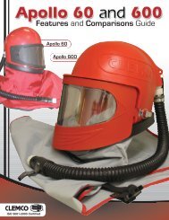
8.1 <strong>Blast</strong> Head and Control Assembly, Figure 3<br />
Item Description Stock No.<br />
1. Control assembly,<br />
includes items 8, 9, and 10 ....................... 12383<br />
2. Head, vacuum,<br />
includes set screws and item 3 in alum. .12300<br />
3. Insert, tube<br />
aluminum, standard ............................... 12175<br />
boron carbide, optional .......................... 12409<br />
4. Collar ......................................................... 13890<br />
5. Nozzle,<br />
Tungsten carbide<br />
CT-2, 1/8" orifice ................................. 01351<br />
CT-3, 3/16" orifice, standard .............. 01352<br />
CT-4, 1/4" orifice ................................. 01353<br />
Boron carbide, CTB-3 ............................ 21091<br />
6. Nozzle washer, pack of 10 ........................ 21580<br />
7. Retainer, brush ......................................... 12039<br />
8. Cover, switch ............................................ 11587<br />
9. Switch ....................................................... 12119<br />
10. Gasket, 1/8" x 2" foam, per foot<br />
1 foot min., trim to fit .............................. 13089<br />
11. Hose, blast 1/2" ID x 25 ft., coupled<br />
includes item 12 and coupling ............... 01268<br />
12. Nozzle holder, CHE, 1/2" .......................... 00577<br />
13. Hose, vacuum, 1-1/2" x 20 ft. .................... 12450<br />
14. Clamp ........................................................ 12750<br />
15. Flat Surface Brush .................................... 11569<br />
16. Inside Corner Brush .................................. 11570<br />
17. Outside Corner Brush ............................... 11571<br />
7.11.4 Inspect the diaphragm outlet valve for wear.<br />
7.11.5 Inspect pop-up valve and seat for alignment and<br />
wear.<br />
11<br />
14<br />
12<br />
6<br />
5<br />
4<br />
2<br />
3<br />
7<br />
17<br />
7.11.6 Blocked or leaking control line. Check all fittings<br />
for blockage or leaks.<br />
7.11.7 Finger switch or solenoid valve malfunction.<br />
Check by qualified electrician.<br />
7.11.8 Inspect the check valve for obstruction or<br />
broken flap.<br />
10<br />
9<br />
1<br />
8<br />
13<br />
14<br />
15<br />
16<br />
Figure 3
SUPER COMET PRESSURE BLAST and RECOVERY MACHINE Page 10<br />
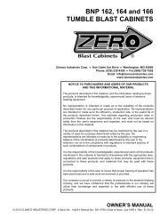
8.2 <strong>Blast</strong> Machine, Figure 4<br />
Item Description Stock No.<br />
1. Ball valve with handle, 1" .......................... 02396<br />
2. Handle, 1" ball valve ................................. 22531<br />
3. Pop-up valve ............................................. 01242<br />
4. Seat, pop-up ............................................. 01245<br />
5. Check valve, 1" swing .............................. 12187<br />
6. Metering valve, Sentinel fine mesh .......... 21439<br />
7. Inspection door assembly, 3" x 4" ............ 01267<br />
8. Gasket, 3" x 4" inspection door ................ 01249<br />
9. Regulator, 1/4" pilot, with gauge .............. 12050<br />
10. Gauge, pressure, 1/8" cbm ...................... 01908<br />
11. Solenoid, 4-way ........................................ 12197<br />
12. Muffler, 1/4" bronze .................................. 03988<br />
13. Valve, 1/2" diaphragm outlet .................... 02512<br />
14. Adaptor, 1" male NPT x 1" male flare ....... 11720<br />
15. Pusher line assembly ............................... 22508<br />
16. Muffler, exhaust ........................................ 05068<br />
17. Regulator, 1" pilot operated with gauge ... 12052<br />
18. Air filter, auto-drain ................................... 22425<br />
19. Gasket, 5/16" x 1" adhesive backed,<br />
(4 ft. required) ........................................ 00187<br />
20. Fitting, elbow 1/4" NPT x 3/8" tube ........... 11685<br />
21. Fitting, straight 1/4" NPT x 3/8" tube ........ 11736<br />
22. Tubing, 3/8" OD poly, specify ft. required . 12478<br />
23. CFP-P Coupling w/nipple 1-1/4″ NPT ...... 10806<br />
24. Gasket, CQGP-3 pack of 10 ..................... 08853<br />
25. Coupling, 1/2" ID hose, CQA-1/2 .............. 00599<br />
26. Gasket, CQG, pkg of 10 ........................... 00850<br />
27. Nozzle holder, CHE-1/2 ............................ 00577<br />
28. <strong>Blast</strong> hose, 1/2" ID x 25 ft. coupled,<br />
includes items 25 & 27 .......................... 01268<br />
20<br />
22<br />
10<br />
9<br />
20<br />
22<br />
11<br />
21<br />
19<br />
12<br />
1 21<br />
6 13<br />
18<br />
4<br />
3<br />
7<br />
17<br />
10<br />
2<br />
5<br />
1<br />
14<br />
8<br />
22<br />
20<br />
6<br />
15<br />
5<br />
23<br />
24<br />
26<br />
25<br />
28<br />
27<br />
Figure 4
SUPER COMET PRESSURE BLAST and RECOVERY MACHINE Page 11<br />
8.3 Dust Collector, Figure 5<br />
Item Description Stock No.<br />
1. Spring Latch .............................................11876<br />
2. Gasket, door ............................................13481<br />
3. Gasket, 5/16" x 1" adhesive backed,<br />
(3 ft. required) .......................................00187<br />
4. Dust Bag, 20” Long, 12 required .............11506<br />
5. Gasket, air injector ...................................11754<br />
6. Gasket, motor adaptor .............................11781<br />
7. Motor ........................................................12315<br />
8.6 Reclaimer, Figure 6<br />
Item Description Stock No.<br />
1. Debris screen .......................................... 21265<br />
2. Gasket, door ............................................ 11745<br />
3. Gasket, reclaimer mount ......................... 11755<br />
4. Hose, vacuum, 1-1/2" x 20 ft. .................. 12450<br />
5. Clamp ...................................................... 12750<br />
6. Gasket, 5/16" x 1" adhesive backed,<br />
(4 ft. required) ...................................... 00187<br />
7. Spring latch assembly ............................. 12263<br />
8. Wear plate ............................................... 13882<br />
3<br />
4<br />
8<br />
5<br />
4<br />
2<br />
1<br />
5 1<br />
3<br />
2<br />
7<br />
6<br />
7<br />
6<br />
Figure 5<br />
Figure 6<br />
8.4 Electrical, Refer to the schematic packed in<br />
the electrical panel for items not listed<br />
Item Description Stock No.<br />
(-) Transformer .............................................12172<br />
(-) Relay, 24 volts .........................................12047<br />
(-) Switch ......................................................12127<br />
8.5 Miscellaneous<br />
Caster, 4 inch, each ..............................................13142<br />
Lock pins (pkg of 25) for twist-on couplings ..........11203<br />
Safety cable, 1/2" hose .........................................15012