BNP 162, 164 and 166 TUMBLE BLAST CABINETS - Clemco ...
BNP 162, 164 and 166 TUMBLE BLAST CABINETS - Clemco ...
BNP 162, 164 and 166 TUMBLE BLAST CABINETS - Clemco ...

You also want an ePaper? Increase the reach of your titles
YUMPU automatically turns print PDFs into web optimized ePapers that Google loves.
<strong>BNP</strong> <strong>162</strong>, <strong>164</strong> <strong>and</strong> <strong>166</strong><br />
<strong>TUMBLE</strong> <strong>BLAST</strong> <strong>CABINETS</strong><br />
<strong>Clemco</strong> Industries Corp. One Cable Car Drive Washington, MO 63090<br />
Phone: (636) 239-4300 FAX (800) 726-7559<br />
Email: info@clemcoindustries.com<br />
www.clemcoindustries.com<br />
NOTICE TO PURCHASERS AND USERS OF OUR PRODUCTS<br />
AND THIS INFORMATIONAL MATERIAL<br />
The products described in this material, <strong>and</strong> the information relating to those<br />
products, is intended for knowledgeable, experienced users of abrasive<br />
blasting equipment.<br />
No representation is intended or made as to the suitability of the products<br />
described herein for any particular purpose of application. No representations<br />
are intended or made as to the efficiency, production rate, or the useful life of<br />
the products described herein. Any estimate regarding production rates or<br />
production finishes are the responsibility of the user <strong>and</strong> must be derived<br />
solely from the user’s experience <strong>and</strong> expertise, <strong>and</strong> must not be based on<br />
information in this material.<br />
The products described in this material may be combined by the user in a<br />
variety of ways for purposes determined solely by the user. No<br />
representations are intended or made as to the suitability or engineering<br />
balance of the combination of products determined by the user in his<br />
selection, nor as to the compliance with regulations or st<strong>and</strong>ard practice of<br />
such combinations of components or products.<br />
It is the responsibility of the knowledgeable, experienced users of the products<br />
mentioned in this material to familiarize themselves with the appropriate laws,<br />
regulations <strong>and</strong> safe practices that apply to these products, equipment that is<br />
connected to these products, <strong>and</strong> materials that may be used with these<br />
products.<br />
It is the responsibility of the user to insure that proper training of operators has<br />
been performed <strong>and</strong> a safe work environment is provided.<br />
Our company is proud to provide a variety of products to the abrasive blasting<br />
industry, <strong>and</strong> we have confidence that the professionals in our industry will<br />
utilize their knowledge <strong>and</strong> expertise in the safe efficient use of these<br />
products.<br />
OWNER’S MANUAL<br />
© 2012 CLEMCO INDUSTRIES CORP. Stock No.: 14429 Manual No.: 921-0790 Date of Issue: July 1990 Rev.: E, 03/12
<strong>BNP</strong> <strong>162</strong>, <strong>164</strong> <strong>and</strong> <strong>166</strong> <strong>TUMBLE</strong> <strong>BLAST</strong> <strong>CABINETS</strong> Page 1<br />
1.0 INTRODUCTION<br />
1.1 Scope of Manual<br />
1.1.1 These instructions cover set-up, operation,<br />
maintenance, troubleshooting, optional accessories,<br />
<strong>and</strong> replacement parts for <strong>BNP</strong> 160's series suction<br />
tumble blast cabinets, all with reclaimer <strong>and</strong> pushthrough<br />
dry filter <strong>and</strong> motor drive options. A<br />
supplemental manual is provided for the optional<br />
reverse-pulse dust collector.<br />
1.1.2 These instructions also contain important<br />
information required for safe operation of the cabinet.<br />
Before using this equipment, all personnel associated<br />
with the blast cabinet operation must read this entire<br />
manual, <strong>and</strong> all accessory manuals to become familiar<br />
with the operation, parts, <strong>and</strong> terminology.<br />
1.2 Safety Alerts<br />
1.2.1 <strong>Clemco</strong> uses safety alert signal words, based<br />
on ANSI Z535.4-1998, to alert the user of a potentially<br />
hazardous situation that may be encountered while<br />
operating this equipment. ANSI's definitions of the<br />
signal words are as follows:<br />
This is the safety alert symbol. It is used<br />
to alert the user of this equipment of<br />
potential personal injury hazards.<br />
Obey all safety messages that follow this symbol to<br />
avoid possible injury or death.<br />
CAUTION<br />
Caution used without the safety alert symbol<br />
indicates a potentially hazardous situation<br />
which, if not avoided, may result in property<br />
damage.<br />
CAUTION<br />
Caution indicates a potentially hazardous<br />
situation which, if not avoided, may result in<br />
minor or moderate injury.<br />
WARNING<br />
Warning indicates a potentially hazardous<br />
situation which, if not avoided, could result in<br />
death or serious injury.<br />
DANGER<br />
Danger indicates an imminently hazardous<br />
situation which, if not avoided, will result in<br />
death or serious injury.<br />
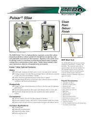
1.3 General Description<br />
1.3.1 <strong>BNP</strong> tumble cabinets blasts batches of small<br />
parts, using fixed nozzles <strong>and</strong> a rotating barrel.<br />
1.3.2 Tumble cabinets consist of three major<br />
components:<br />
1. Cabinet Enclosure<br />
2. Reclaimer<br />
3. Dust Collector<br />
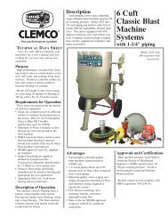
See Figure 1 for arrangement of components with a dry<br />
filter. The model shown is a <strong>164</strong> with a 600 cfm reclaimer<br />
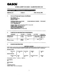
<strong>and</strong> dry filter. Figure 2 shows a free st<strong>and</strong>ing 900 cfm<br />
reclaimer connected to a reverse-pulse dust collector.<br />
1.3.3 The load capacity of the barrel depends on the<br />
model. St<strong>and</strong>ard cabinets are supplied as follows:<br />
MODEL <strong>BNP</strong>-<strong>162</strong> <strong>BNP</strong>-<strong>164</strong> <strong>BNP</strong>-<strong>166</strong><br />
No. of Guns two four six<br />
Max. volume 1 cu ft 2 cu. ft. 3 cu. ft.<br />
Max. weight 100 lb. 200 lb. 300 lb.<br />
Reclaimer cfm 300 or 600 600 or 900 900<br />
NOTE: The reclaimer size is determined by the cabinet<br />
weldment; therefore, reclaimer sizes are not<br />
interchangeable. 300 cfm <strong>and</strong> 600 cfm reclaimers are<br />
attached to the cabinet enclosure, 900 cfm reclaimers<br />
are free st<strong>and</strong>ing.<br />
1.4 Theory of Operation<br />
1.4.1 When parts are loaded into the barrel, the air<br />
supply <strong>and</strong> exhauster are turned "on", <strong>and</strong> the cabinet<br />
door is closed, the cabinet is ready for operation by<br />
engaging the timer located in the electrical panel mounted<br />
on top of the cabinet. Starting the timer causes air to flow<br />
through the blast guns. Air moving through the guns<br />
draws media into the blast gun mixing chamber. The<br />
media mixes with the air <strong>and</strong> is propelled out the nozzles.<br />
As the barrel rotates, the parts tumble in the blast<br />
stream ensuring that all parts <strong>and</strong> surfaces are<br />
uniformly cleaned. Some of the blast media remains in<br />
the barrel to cushion the parts as they tumble. A portion<br />
of the blast media, along with fines, dust, <strong>and</strong> byproducts<br />
generated by blasting, flows through the<br />
adjustable slide gates into the cabinet hopper. These<br />
© 2012 CLEMCO INDUSTRIES CORP. www.clemcoindustries.com Manual No. 14429 Rev. E
<strong>BNP</strong> <strong>162</strong>, <strong>164</strong> <strong>and</strong> <strong>166</strong> <strong>TUMBLE</strong> <strong>BLAST</strong> <strong>CABINETS</strong> Page 2<br />
particles are drawn into the reclaimer for separation. Dust<br />
<strong>and</strong> fines are first separated from the reusable blast<br />
media. Next, the media is screened of oversize particles,<br />
<strong>and</strong> returned to the reclaimer hopper for reuse. Dust <strong>and</strong><br />
fines are drawn through the reclaimer into the dry filter or<br />
dust collector, which traps the dust <strong>and</strong> discharges clean<br />
air. Blasting automatically stops when the timed cycle is<br />
completed.<br />
Optional Variable Speed<br />
Control Panel<br />
Tumble Barrel<br />
Door Interlock<br />
Actuator<br />
Air Filter, Compressed air inlet<br />
Air Inlet Ducts<br />
Parts Tray<br />
Exhauster<br />
Optional Externally<br />
Adjustable Vortex<br />
Pilot Regulator<br />
Pressure Regulator<br />
Blast-Gun Rack<br />
Reclaimer<br />
Guard, Drive<br />
Mechanism<br />
Damper<br />
Dry Filter<br />
Dust Collector<br />
Debris Screen<br />
Media Hose<br />
Metering Valve<br />
Some items are rotated for clarity<br />
Dust Drawer<br />
Figure 1<br />
© 2012 CLEMCO INDUSTRIES CORP. www.clemcoindustries.com Manual No. 14429 Rev. E
<strong>BNP</strong> <strong>162</strong>, <strong>164</strong> <strong>and</strong> <strong>166</strong> <strong>TUMBLE</strong> <strong>BLAST</strong> <strong>CABINETS</strong> Page 3<br />
1.5 Dust Collector Options<br />
WARNING<br />
Prolonged exposure to any dust could result in<br />
serious lung disease <strong>and</strong> death. Short term<br />
ingestion of toxic materials, such as lead dust<br />
or dust from other heavy metals <strong>and</strong> corrosives,<br />
could cause serious respiratory injury or death.<br />
Identify all materials that are to be removed by<br />
blasting. Use reverse-pulse dust collectors with<br />
HEPA after-filters if lead coating or any other<br />
toxic materials are being removed by the<br />
blasting process. Do not use dust collectors<br />
with simple cloth filters for those applications.<br />
1.5.1 Dry Filter: Uses tubular filters which trap dust<br />
on their inner surfaces. A dry filter is for use with light to<br />
moderate dust contamination. The filters must be<br />
shaken manually approximately every twenty minutes,<br />
<strong>and</strong> the dust drawer emptied regularly. This type of dust<br />
collection must never be used in applications which<br />
generate toxic dust.<br />
1.5.2 Reverse Pulse Dust Collector: The most<br />
efficient dust collector option. Cartridge filters are<br />
automatically cleaned by a periodic pulse of compressed<br />
air. This type of dust collector used with the optional<br />
HEPA filter must be used in applications in which toxic<br />
dust is generated. See separate manual for operation of<br />
reverse-pulse dust collectors.<br />
Adjustable<br />
Vortex<br />
Damper<br />
RP Dust Collector<br />
Duct Inlet<br />
1.5.3 HEPA Filter: Optional HEPA after-filters provide<br />
additional filtration <strong>and</strong>, are available for use with reversepulse<br />
collector only. HEPA filters must be used when<br />
removing lead coatings or any other toxic materials.<br />
1.6 Nozzle Options<br />
1.6.1 Ventilation requirements limit st<strong>and</strong>ard cabinets to<br />
5/16" nozzle <strong>and</strong> No. 5 (5/32" orifice) air jets. In some<br />
applications, where compressed air is limited, No. 4 (1/8"<br />
orifice) air jets may be used, but blast rates will decrease<br />
accordingly. See Section 1.8. Unless otherwise specified<br />
at the time of order, cabinets are supplied with ceramic<br />
nozzles. More durable tungsten carbide <strong>and</strong> boron<br />
carbide nozzles are available <strong>and</strong> are shown under<br />
Accessories <strong>and</strong> Replacement Parts in Sections 9.1 or<br />
9.3. Use boron carbide nozzles when blasting with<br />
aggressive media, such as those listed in Section 1.7.4.<br />
1.7 Media<br />
1.7.1 <strong>BNP</strong> Tumble Blast Cabinets utilize most<br />
common reusable media 30 mesh to 180 mesh, that is<br />
specifically manufactured for dry blasting (glass bead<br />
<strong>and</strong> aluminum oxide are most commonly used). The<br />
usable media size range depends on the number of<br />
nozzles <strong>and</strong> reclaimer cleaning rate. Several factors<br />
affecting the reclaimer cleaning rate include: reclaimer<br />
size, blast pressure, media/air mixture, media friability,<br />
contamination of parts being cleaned, <strong>and</strong> humidity.<br />
Media sizes noted are guidelines only, <strong>and</strong> are based on<br />
st<strong>and</strong>ard nozzles <strong>and</strong> average conditions.<br />
Media finer than those recommended may increase<br />
carryover to the dust collector. Using media 200 mesh<br />
<strong>and</strong> finer will usually require the addition of the optional,<br />
externally adjustable vortex cylinder. See Section 5.5.<br />
The vortex cylinder is st<strong>and</strong>ard on pull-through systems<br />
(cabinets with reverse-pulse dust collectors). Media<br />
coarser than those recommended may be too dense for<br />
the reclaimer to recover from the cabinet hopper.<br />
1.7.2 Steel: Steel grit or shot should not be used with<br />
st<strong>and</strong>ard tumble cabinets.<br />
1.7.3 S<strong>and</strong> <strong>and</strong> Slag: S<strong>and</strong> should never be used<br />
because of the hazards of using media containing free<br />
silica. Slags are not recommended because they rapidly<br />
break down.<br />
Shown with 900 cfm reclaimer<br />
<strong>and</strong> reclaimer extension<br />
Figure 2<br />
1.7.4 Silicon Carbide, Aluminum Oxide, <strong>and</strong><br />
Garnet: These are the most aggressive, high-volume<br />
abrasives in the blasting industry. Aggressive media<br />
such as these may be used, but the service life will be<br />
reduced on any equipment components which come in<br />
contact with the abrasive. To avoid unscheduled down<br />
time, periodically inspect the reclaimer wear plate,<br />
© 2012 CLEMCO INDUSTRIES CORP. www.clemcoindustries.com Manual No. 14429 Rev. E
<strong>BNP</strong> <strong>162</strong>, <strong>164</strong> <strong>and</strong> <strong>166</strong> <strong>TUMBLE</strong> <strong>BLAST</strong> <strong>CABINETS</strong> Page 4<br />
exhauster housing <strong>and</strong> paddle wheel, hoses, <strong>and</strong> nozzle<br />
for abrasive wear.<br />
When occasionally using aggressive abrasive, use the<br />
optional aluminum oxide kit. When routinely using these<br />
media, use a fully-rubber-lined reclaimer, a reverse<br />
pulse dust collector, <strong>and</strong> boron carbide nozzles to<br />
prolong service life. See Optional Accessories in Section<br />
9.1.<br />
1.7.5 Glass Bead: Most beads are treated to ensure<br />
free-flow operation even under moderately high humidity<br />
conditions. Glass beads subjected to excessive moisture<br />
may be reused after thorough drying <strong>and</strong> breaking up of<br />
any lumps.<br />
1.7.6 Fine-mesh Media: The optional adjustable<br />
vortex cylinder should be installed when using 200-mesh<br />
<strong>and</strong> finer media. NOTE: The adjustable vortex cylinder is<br />
st<strong>and</strong>ard on pull-through systems (cabinets with<br />
reverse-pulse dust collectors). When using very fine<br />
media (200 mesh <strong>and</strong> finer), the inlet baffle of the<br />
reclaimer may also need to be removed. Consult the<br />
factory before proceeding with this option.<br />
1.7.7 Lightweight Media: Plastic media <strong>and</strong> most<br />
agricultural media are not recommended with the tumble<br />
cabinets; They are usually too light for suction blast<br />
applications, <strong>and</strong> may bridge in the barrel <strong>and</strong> hopper.<br />
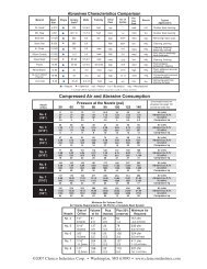
1.8 Compressed Air Requirements<br />
1.8.1 The size of the compressor required to operate<br />
the cabinet depends on the size of air jet*, the number of<br />
guns <strong>and</strong> blasting pressure. See table in Figure 3 to<br />
determine cfm requirements. Consult with a compressor<br />
supplier for suggested compressor size based on the air<br />
consumption.<br />
NOTE: A separate air line is required for the optional<br />
reverse pulse dust collector.<br />
Model Jet Nozzles CFM PSI<br />
<strong>162</strong> *1/8" 2 42 80<br />
<strong>162</strong> 5/32" 2 64 80<br />
<strong>164</strong> *1/8" 4 84 80<br />
<strong>164</strong> 5/32" 4 128 80<br />
<strong>166</strong> *1/8" 6 126 80<br />
<strong>166</strong> 5/32 6 192 80<br />
Air Consumption in cfm<br />
*1/8" jets decrease blast rates by approximately 30%.<br />
Figure 3<br />
1.8.2 The air filter at the air inlet connection reduces<br />
condensed water from the compressed air. Its use is<br />
especially important in areas of high humidity, or when<br />
fine-mesh media are used. Moisture causes media to<br />
clot <strong>and</strong> inhibits free flow through the feed assembly. If<br />
moisture problems persist, an air dryer may be required.<br />
1.9 Electrical Requirements<br />
1.9.1 Electrical requirements depend on the size <strong>and</strong><br />
type of motors <strong>and</strong> electrical package. Electrical<br />
schematics are packed inside the control panel. Refer to<br />
the schematic for electrical requirements.<br />
2.0 INSTALLATION<br />
2.1 General Installation Notes<br />
2.1.1 See Figure 1 (<strong>and</strong> Figure 2 for optional reversepulse<br />
collector) for the general arrangement. Place all<br />
components in a convenient location where compressed<br />
air <strong>and</strong> electrical service are available. The cabinet<br />
location must comply with OSHA <strong>and</strong> local safety codes.<br />
Allow for full access to all doors <strong>and</strong> service areas, <strong>and</strong><br />
for efficient h<strong>and</strong>ling of parts. Provide enough clearance<br />
in front of the dust collector to remove the dust drawer<br />
without tipping. Place free-st<strong>and</strong>ing reclaimers directly<br />
behind the cabinet. Place all components to route hoses<br />
with as few bends as possible. Determine the best<br />
location, <strong>and</strong> position all units before final assembly.<br />
2.2 Level Cabinet Enclosure<br />
2.2.1 Level the cabinet by using shims as necessary<br />
under cabinet corners. A cabinet that is not level may<br />
have problems with door closing <strong>and</strong> barrel tracking.<br />
2.3 Connect Conveying Hose<br />
2.3.1 Connect flexible conveying hose between the<br />
cabinet hopper transition <strong>and</strong> reclaimer inlet adaptor. It<br />
is easier to slip the hose over the adaptors <strong>and</strong> create a<br />
tighter seal if the first two or three inches of wire are<br />
removed from the inside of the hose. Use care not to<br />
damage the hose. Clamp flex hose securely in position<br />
with worm clamps provided. NOTE: The hose wire helps<br />
dissipate static electricity in the conveying hose, <strong>and</strong><br />
also helps ground each segment. In order for the hose<br />
wire to dissipate static electricity, the wire must touch the<br />
metal of each segment.<br />
© 2012 CLEMCO INDUSTRIES CORP. www.clemcoindustries.com Manual No. 14429 Rev. E
<strong>BNP</strong> <strong>162</strong>, <strong>164</strong> <strong>and</strong> <strong>166</strong> <strong>TUMBLE</strong> <strong>BLAST</strong> <strong>CABINETS</strong> Page 5<br />
2.4 Connect Compressed Air Supply Line(s)<br />
WARNING<br />
Failure to observe the following before<br />
connecting the equipment to the compressed<br />
air source could cause serious injury or death<br />
from the sudden release of compressed air.<br />
• Lockout <strong>and</strong> Tagout the compressed air supply.<br />
• Bleed the compressed air supply line.<br />
WARNING<br />
To avoid the risk of injury from compressed air,<br />
install an isolation valve <strong>and</strong> bleed-off valve<br />
where the air supply it tapped into the<br />
compressed air system. This enables<br />
depressurization of the compressed air circuit<br />
before performing maintenance.<br />
2.4.1 Install an air fitting to the compressed-air filter<br />
located on the left side of the cabinet that is compatible<br />
with the compressed-air supply hose. See Section 2.4.2<br />
2.4.2 Install an isolation valve at the air source to<br />
enable depressurization for service. Connect an air line<br />
from the air source to the air filter inlet. For best blasting<br />
performance, size the air line as follows:<br />
<strong>BNP</strong>-<strong>162</strong> .................................................... 1" ID or larger<br />
<strong>BNP</strong>-<strong>164</strong> .............................................. 1-1/4" ID or larger<br />
<strong>BNP</strong>-<strong>166</strong> .................................................. 1-1/2" or larger<br />
NOTE: A separate air line is required for the optional<br />
reverse pulse dust collector.<br />
WARNING<br />
If twist-on type air hose couplings are used,<br />
they must be secured by safety pins or wires to<br />
prevent accidental disconnection while under<br />
pressure. Hose disconnection while under<br />
pressure could cause serious injury.<br />
2.5 Ground Cabinet<br />
2.5.1 To prevent static electricity build up, attach an<br />
external grounded wire from an earth ground to the<br />
grounding lug on the rear of the cabinet.<br />
2.6 Connect Electrical Service<br />
WARNING<br />
Shorting electrical components could result in<br />
serious electrical shocks, or equipment<br />
damage. All electrical work <strong>and</strong> any work done<br />
inside the panel must be performed by a<br />
qualified electrician, <strong>and</strong> comply with<br />
applicable codes.<br />
NOTE: Schematics are packed in the electrical panel.<br />
After wiring is completed, keep the schematic with the<br />
manual for future reference <strong>and</strong> for electrical<br />
replacement parts.<br />
2.6.1 As much wiring as possible has been completed<br />
at the factory. The electrician needs to provide service to<br />
the motor starter in the electrical panel mounted on the<br />
cabinet, <strong>and</strong> connect the conduit <strong>and</strong> wiring from the<br />
starter to the motor on free st<strong>and</strong>ing reclaimers. Refer to<br />
the schematic packed in the panel. NOTE: The user<br />
must provide conduit <strong>and</strong> wiring from the starter to the<br />
motor for RP Collectors.<br />
2.6.2 Whether voltage is 230 or 460 is determined at<br />
time of order, <strong>and</strong> heaters are provided accordingly.<br />
2.6.3 Supply service from the user's disconnect to the<br />
electrical panel as shown on the schematic.<br />
2.6.4 Observe the subsequent warning <strong>and</strong> check the<br />
rotation of the motors. To check, jog the exhauster<br />
starter (momentarily turn switch on <strong>and</strong> off). This will<br />
cause the motor to rotate slowly. Look through the slots<br />
in the fan housing on top of the motor where rotation of<br />
the fan can easily be observed. Proper rotation of the<br />
exhauster is indicated by the arrow on the exhauster<br />
housing. The fan should rotate toward the scroll outlet.<br />
The tumble barrel should rotate clockwise when viewed<br />
from the gear reducer side.<br />
WARNING<br />
Do not look into the reclaimer exhauster outlet<br />
while the paddle wheel is turning. Injury to the<br />
eye or face could occur from objects being<br />
ejected from the exhauster.<br />
2.6.5 Check the amperage on initial start up. If the<br />
motor draws excessive amperage, gradually close the<br />
damper until the amperage is within the specifications<br />
shown on the motor plate. The damper is located on the<br />
inlet of dry filters, <strong>and</strong> on the exhauster outlet of reversepulse<br />
collectors.<br />
© 2012 CLEMCO INDUSTRIES CORP. www.clemcoindustries.com Manual No. 14429 Rev. E
<strong>BNP</strong> <strong>162</strong>, <strong>164</strong> <strong>and</strong> <strong>166</strong> <strong>TUMBLE</strong> <strong>BLAST</strong> <strong>CABINETS</strong> Page 6<br />
2.7 Dry Filter Dust Collector. See separate<br />
manual for Reverse-Pulse Dust Collector.<br />
2.7.1 The dry filter duct inlet adaptor can be converted<br />
to the left or right. If it is more convenient to have the<br />
inlet on the opposite side, switch the inlet adaptor for the<br />
blank cover.<br />
the timer times out. Note: Optional electrical package<br />
timer does not require resetting after blasting, unless the<br />
blasting duration changes.<br />
2.7.2 Connect the flexible exhaust hose between the<br />
reclaimer outlet <strong>and</strong> dry filter inlet adaptor. It is easier to<br />
slip the hose over the adaptors, <strong>and</strong> create a tighter seal<br />
if the first two or three inches of wire are removed from<br />
the inside of the hose. Use care not to damage the hose.<br />
Secure the hose with worm clamps. NOTE: The hose<br />
wire helps dissipate static electricity in the conveying<br />
hose, <strong>and</strong> also helps ground each segment. In order for<br />
the hose wire to dissipate static electricity, the wire must<br />
touch the metal of each segment.<br />
1<br />
2<br />
3<br />
St<strong>and</strong>ard Electrical Package<br />
2<br />
3.0 FIELD INSTALLED ACCESSORIES<br />
3.1 Manometer<br />
3.1.1 Constant static pressure is necessary for precise<br />
separation, as the reclaimer’s efficiency is accomplished<br />
by a centrifugal balance of particle weight <strong>and</strong> size. The<br />
air balance <strong>and</strong> static pressure are set by adjusting the<br />
outlet damper. The manometer measures static pressure.<br />
Use the instruction sheet provided with the manometer,<br />
for installation <strong>and</strong> operation instructions. The optional<br />
manometer kit is listed in Section 9.1.<br />
3.2 Drum Divider Kit<br />
3.2.1 Drum dividers split the barrel chamber into<br />
separate compartments. This permits simultaneous<br />
blasting of different parts. Barrels should not be divided<br />
into compartments containing less than two nozzles.<br />
4.0 OPERATION<br />
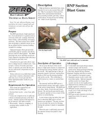
4.1. Control Panel Operation, Ref. Figure 4<br />
Item<br />
Description <strong>and</strong> Function<br />
1. Exhauster Switch: Pulling out the button starts<br />
the exhauster, pushing in the button stops the<br />
exhauster. Other controls will not operate unless the<br />
exhauster is running.<br />
2. Timer: Sets duration of the blast cycle. The<br />
timer switch also starts the blast cycle on st<strong>and</strong>ard<br />
electrical package. Blasting automatically stops when<br />
Item<br />
4<br />
7<br />
1<br />
5 6<br />
Optional Electrical Package<br />
with variable speed control<br />
<strong>and</strong> door interlock<br />
Description <strong>and</strong> Function<br />
Figure 4<br />
3. Barrel Jog: The exhauster must be on before<br />
engaging the switch. Pressing the momentary switch<br />
rotates the barrel. The barrel continues to rotate as long<br />
as pressure is maintained on the switch.<br />
4. Door Interlock: (Optional Electrical Package<br />
Only) When the door is open, blast guns are<br />
disengaged, preventing blasting.<br />
The following controls are supplied with the optional<br />
electrical package only.<br />
5. Sequence Switch: When the timer <strong>and</strong> gun<br />
controls are set, blasting starts <strong>and</strong> stops by pulling <strong>and</strong><br />
pushing the sequence switch.<br />
6. Guns switch: This switch engages <strong>and</strong><br />
disengages the blast guns. If the switch is pulled out<br />
"on", blasting starts when the sequence switch is<br />
engaged. If the switch is pushed in "off", all tumble<br />
operations except blasting starts when the sequence<br />
switch is engaged.<br />
7. Speed Control: Controls the rotation speed of<br />
the tumble barrel.<br />
3<br />
© 2012 CLEMCO INDUSTRIES CORP. www.clemcoindustries.com Manual No. 14429 Rev. E
<strong>BNP</strong> <strong>162</strong>, <strong>164</strong> <strong>and</strong> <strong>166</strong> <strong>TUMBLE</strong> <strong>BLAST</strong> <strong>CABINETS</strong> Page 7<br />
4.2 Media Loading <strong>and</strong> Unloading<br />
4.4 Blasting Operation<br />
4.2.1 Media Loading: With the exhauster off, add<br />
clean dry media, by pouring it through the reclaimer fill<br />
door. Do not fill above the cone on the reclaimer. Do not<br />
pour media directly into the cabinet hopper, as<br />
overfilling may occur. Overfilling will result in media<br />
carryover to the dust collector <strong>and</strong> possible blockage in<br />
the conveying hose. Refill only after all media has been<br />
recovered from the cabinet.<br />
The approximate amount of media to charge the system<br />
is as follows:<br />
<br />
<br />
<br />
CAUTION<br />
Always close cabinet, reclaimer <strong>and</strong> dust<br />
collector doors before blasting. Keep all<br />
doors closed during blasting.<br />
After blasting, keep doors closed <strong>and</strong><br />
exhauster on until the cabinet is clear of all<br />
airborne dust.<br />
Stop blasting immediately if dust leaks are<br />
detected.<br />
300 CFM Reclaimer .................... 50 Lb. (.5 cu. ft.) Media<br />
600 CFM Reclaimer .................. 75 Lb. (.75 cu. ft.) Media<br />
900 CFM Reclaimer .................... 100 Lb.(1 cu. ft.) Media<br />
4.2.2 Media Unloading: To empty the cabinet <strong>and</strong><br />
reclaimer of media, allow all media to be recovered from<br />
the cabinet, turn off the exhauster <strong>and</strong> place an empty<br />
container under the metering valve manifold (or metering<br />
valve on <strong>162</strong> units). Unscrew the plastic plug, permitting<br />
media to flow into the container. If media does not flow,<br />
it has caked. Open the fill door <strong>and</strong> stir media until it<br />
starts to flow. Replace the plug when the reclaimer is<br />
empty.<br />
4.3 Loading <strong>and</strong> Unloading Parts<br />
4.3.1 Open the cabinet door, <strong>and</strong> pull the exhauster<br />
button switch to start the exhauster. Press the barrel jog<br />
button until the barrel loading door is facing forward.<br />
4.3.2 Unlatch the barrel door clamps <strong>and</strong> remove the<br />
door.<br />
4.3.3 Parts must be free of oil, water, grease, or other<br />
contaminants that will cause media to clump, or clog<br />
filters.<br />
4.3.4 Load parts through the barrel door. Do not<br />
overload the barrel. The following table shows maximum<br />
load capacity in weight <strong>and</strong> cubic feet.<br />
MODEL <strong>BNP</strong>-<strong>162</strong> <strong>BNP</strong>-<strong>164</strong> <strong>BNP</strong>-<strong>166</strong><br />
Max. volume 1 cu ft 2 cu. ft. 3 cu. ft.<br />
Max. weight 100 lb. 200 lb. 300 lb.<br />
4.3.5 Check gun rack angle adjustment per Section<br />
5.2.<br />
4.3.6 Close the barrel door <strong>and</strong> latch it securely.<br />
4.3.7 Close the cabinet door. Be certain door is<br />
latched securely. Optional door interlock system will<br />
prevent blasting.<br />
4.4.1 Slowly open the air valve on the air supply hose<br />
to the cabinet. Check for air leaks on the initial start up,<br />
<strong>and</strong> periodically thereafter.<br />
4.4.2 Turn on the exhauster by pulling the exhauster<br />
button.<br />
4.4.3 Adjust the pilot pressure regulator located on the<br />
top, left side of the cabinet, to the required blast<br />
pressure per Section 5.1.<br />
4.4.4 Load parts, set gun rack angle. See Section 4.3.<br />
4.4.5 For optional electrical package only, set timer<br />
blast duration.<br />
4.4.6 Start the blast cycle as follows:<br />
St<strong>and</strong>ard Electrical Package:<br />
1. Set timer for blast duration. Blasting begins when<br />
timer is set.<br />
Optional electrical package:<br />
1. Set Speed Control<br />
2. Pull Gun Switch "on"<br />
3. Pull Sequence Switch "on".<br />
WARNING<br />
Shut down the cabinet immediately if dust<br />
discharges from the collector or bag. Make sure<br />
that the filters are correctly seated <strong>and</strong> not worn<br />
or damaged. Prolonged breathing of any dust<br />
could result in serious lung disease or death.<br />
Short term ingestion of toxic dust such as lead,<br />
poses an immediate danger to health. Toxicity<br />
<strong>and</strong> health risk vary with type of media <strong>and</strong> dust<br />
generated by blasting. Identify all material being<br />
removed by blasting, <strong>and</strong> obtain a material<br />
safety data sheet for the blast media.<br />
© 2012 CLEMCO INDUSTRIES CORP. www.clemcoindustries.com Manual No. 14429 Rev. E
<strong>BNP</strong> <strong>162</strong>, <strong>164</strong> <strong>and</strong> <strong>166</strong> <strong>TUMBLE</strong> <strong>BLAST</strong> <strong>CABINETS</strong> Page 8<br />
4.4.7 Check media flow per Section 5.3.<br />
4.5 Stop Blasting<br />
4.5.1 Blasting <strong>and</strong> barrel rotation stop when the timer<br />
cycle is complete.<br />
4.5.2 Allow exhauster to run awhile before opening<br />
the door <strong>and</strong> run exhauster until parts are unloaded.<br />
4.5.3 Press the barrel jog button until the barrel<br />
loading door is facing forward, then completely remove<br />
the barrel door.<br />
5.2.1 Load parts into the barrel; close the barrel door;<br />
<strong>and</strong> jog the barrel until it has rotated one revolution. This<br />
places the parts at the angle in which they tumble.<br />
5.2.2 Open the door <strong>and</strong> check the alignment of the<br />
guns by placing a dowel, pencil, or similar object into a<br />
nozzle barrel.<br />
Loosen all three holddown<br />
brackets.<br />
4.5.4 Parts may be unloaded through the barrel door,<br />
or the barrel may be jogged, until parts empty into the<br />
parts tray.<br />
4.5.5 Remove parts from the tray. The parts tray may<br />
be installed with the open end toward the front or back,<br />
place it to most easily h<strong>and</strong>le the parts.<br />
4.5.6 Reload the barrel, or shut off the air supply<br />
valve, drain the air filter, <strong>and</strong> switch off the exhauster.<br />
5.0 ADJUSTMENTS<br />
5.1 Blasting Pressure<br />
5.1.1 The pilot regulator, located on the upper side of<br />
the cabinet, enables the user to adjust blasting pressure<br />
to suit the application. The suitable pressure for most<br />
purposes is 80 psi. Lower pressures may be used for<br />
delicate work. In all cases, highest production can be<br />
achieved only when pressure is carefully monitored.<br />
5.1.2 To adjust, unlock the knob, <strong>and</strong> turn it clockwise<br />
to increase pressure or counter-clockwise to decrease<br />
pressure. Pressure will usually drop from closed-line<br />
pressure when blasting starts. Once operating pressure<br />
is reached, lock the knob to maintain the setting.<br />
5.2 Gun Rack Angle, Ref. Fig. 5<br />
CAUTION<br />
The gun rack must be adjusted to direct the<br />
blast stream toward the parts. If the rack is not<br />
correctly adjusted, the tumble barrel will wear<br />
prematurely <strong>and</strong> parts will require longer blast<br />
cycles.<br />
Figure 5<br />
5.2.3 If the guns do not point toward the center of the<br />
parts, loosen the three gun rack hold-down brackets <strong>and</strong><br />
rotate the rack until the nozzles point to the center of the<br />
parts.<br />
5.2.4 Remove the dowel <strong>and</strong> tighten the hold-down<br />
brackets to maintain the setting.<br />
5.3 Media/Air Mixture, Figure 6<br />
Rotate gun rack until<br />
nozzle (blast stream) is<br />
pointed to the center of<br />
the parts.<br />
5.3.1 Media should flow smoothly <strong>and</strong> evenly through<br />
the hoses. Flow can be observed through the clear<br />
metering valve body.<br />
5.3.2 If media does not flow smoothly, loosen the<br />
locking ring, <strong>and</strong> adjust the metering screw until the upper<br />
holes in the metering stem are closed-off, <strong>and</strong> the lower<br />
holes are fully open. Refer to Figure 6. This adjustment is a<br />
starting point.<br />
© 2012 CLEMCO INDUSTRIES CORP. www.clemcoindustries.com Manual No. 14429 Rev. E
<strong>BNP</strong> <strong>162</strong>, <strong>164</strong> <strong>and</strong> <strong>166</strong> <strong>TUMBLE</strong> <strong>BLAST</strong> <strong>CABINETS</strong> Page 9<br />
Upper holes<br />
fully closed<br />
Adjusting Screw<br />
Locking nut<br />
Lower holes<br />
fully open<br />
5.4.4 If the damper has been adjusted <strong>and</strong> carryover<br />
or excessive dust in the media continues to be a<br />
problem, an optional adjustable vortex cylinder,<br />
(st<strong>and</strong>ard on pull through reclaimers), may help retain<br />
media. This option is usually required only when using<br />
200 mesh <strong>and</strong> finer media, or lightweight media. See<br />
Section 5.5, <strong>and</strong> reclaimer accessories in Section 9.10<br />
(300 cfm <strong>and</strong> 600 cfm) or 9.11 (900 cfm).<br />
5.5 Optional Externally Adjustable Vortex Cylinder<br />
(st<strong>and</strong>ard on pull-through reclaimers). For use with<br />
fine-mesh or lightweight media.<br />
Figure 6<br />
5.3.3 If pulsation occurs in the media hose, either media<br />
is damp <strong>and</strong> caked, or not enough air is entering the media<br />
stream. While blasting, loosen the locking nut <strong>and</strong> slowly<br />
turn the adjusting screw out (counterclockwise when<br />
viewed from the top) until the media flows smoothly.<br />
Tighten the locking nut to maintain the setting.<br />
5.3.4 If media flow is too light, decrease air in the<br />
mixture by turning the metering screw in (clockwise when<br />
viewed from the top) covering more of the holes so less air<br />
enters the media hose. Tighten the locking nut tight to<br />
maintain the setting.<br />
5.4 Static Pressure<br />
5.4.1 Correct static pressure varies with size of<br />
reclaimer <strong>and</strong> the size, weight <strong>and</strong> type of media.<br />
5.4.2 Adjust static pressure by opening (h<strong>and</strong>le<br />
horizontal) or closing (h<strong>and</strong>le vertical) the damper. The<br />
damper is located on the inlet on dry filters, <strong>and</strong> on the<br />
outlet of reverse pulse dust collectors. If the damper is<br />
not opened enough, the reclaimer will not remove fines,<br />
resulting in dusty media <strong>and</strong> possible media blockage in<br />
the conveying hose. If the damper is opened too far, it<br />
may cause carryover (usable media carried into the dust<br />
collector) <strong>and</strong> result in excessive media consumption.<br />
Open only as far as necessary to obtain a balance of<br />
dust removal without media carryover.<br />
5.4.3 A manometer is useful when adjusting or<br />
monitoring static pressure. The manometer kit is listed<br />
under Optional Accessories in Section 9.1. The following<br />
are static pressure starting points for given media. Static<br />
pressure may need to be lower with finer media, higher<br />
with coarser media.<br />
Glass Bead No. 8 to 13 ..................................... 2-1/2 - 3"<br />
Alox. 60 & coarser ................................................... 4 - 5"<br />
Alox. 80 & finer .................................................. 2-1/2 - 3"<br />
5.5.1 The adjusting lever for the vortex cylinder is<br />
mounted on the spacer between the reclaimer body <strong>and</strong><br />
exhauster housing. Start with the lever in the vertical<br />
position. Before adjusting the vortex cylinder, adjust the<br />
damper on the dust collector to increase or decrease<br />
static pressure per Section 5.4. Once the damper has<br />
been adjusted, adjust the cylinder as follows.<br />
5.5.2 Dusty Media: If the reclaimer is not removing<br />
sufficient quantities of dust, raise the cylinder by moving<br />
the lever left toward "COARSE", in 1/4" increments at<br />
the indicator plate. Do not adjust again until the media<br />
has gone through several cycles, to be certain further<br />
adjustment is required.<br />
5.5.3 Media Carryover: If too much usable media is<br />
being carried to the dust collector, lower the vortex<br />
cylinder by moving the lever right toward "FINE", in 1/4"<br />
increments at the indicator plate. Note: If the cylinder is<br />
lowered too far, the reclaimer will again begin to allow<br />
usable media to be carried over, <strong>and</strong> cause abnormally<br />
high static pressure.<br />
5.5.4 When using very fine media (200 mesh <strong>and</strong> finer),<br />
the reclaimer inlet baffle may need to be removed. Consult<br />
the factory before proceeding with this option.<br />
5.6 Door Interlocks, Ref. Figure 7<br />
St<strong>and</strong>ard with optional electrical package<br />
WARNING<br />
Never attempt to override the interlock system.<br />
Doing so could result in injury from unexpected<br />
blasting.<br />
5.6.1 The door interlock disables the blasting control<br />
circuit when the door is open. To enable blasting, the door<br />
interlock switch must be engaged when the door is<br />
closed. The interlock is set at the factory <strong>and</strong> does not<br />
usually require field adjustment unless parts are replaced.<br />
When adjustment is required, proceed as follows.<br />
© 2012 CLEMCO INDUSTRIES CORP. www.clemcoindustries.com Manual No. 14429 Rev. E
<strong>BNP</strong> <strong>162</strong>, <strong>164</strong> <strong>and</strong> <strong>166</strong> <strong>TUMBLE</strong> <strong>BLAST</strong> <strong>CABINETS</strong> Page 10<br />
5.6.2 Close cabinet door.<br />
Optional Electrical Package Control<br />
Panel<br />
Interlock Switch<br />
Adjusting Screw Nut<br />
Loosen, <strong>and</strong> move sideways to<br />
center the adjusting screw on<br />
the interlock switch.<br />
Adjusting Screw<br />
Adjust the screw to engage<br />
the switch when door is<br />
closed.<br />
5.7.2 How far the slide doors are open depend on the<br />
parts <strong>and</strong> media size. Begin with the door set to allow a<br />
small amount of media to fall through the holes as the<br />
barrel turns.<br />
5.7.3 After a short blast cycle, open the barrel loading<br />
door to see how much media is retained in the barrel<br />
<strong>and</strong> if the parts are nicked. Adjust the opening size<br />
accordingly.<br />
Slide door to open or close as<br />
required to retain media cushion.<br />
Actuator Adjusting Bracket<br />
Loosen the bracket screws,<br />
<strong>and</strong> move the bracket up or<br />
down to center the adjusting<br />
screw on the over-travel stop.<br />
Bracket Screws<br />
Cabinet Door<br />
Figure 7<br />
Figure 8<br />
5.6.3 Loosen the actuator bracket screws <strong>and</strong><br />
adjusting screw nut. Move the actuator adjusting bracket<br />
up or down, <strong>and</strong> the adjusting screw sideways, to center<br />
the adjusting screw on the switch button. Tighten the<br />
bracket screws.<br />
5.6.4 Turn the adjusting screw in or out as required to<br />
engage the switch without applying excessive pressure<br />
on it. Tighten the adjusting screw nuts.<br />
5.6.5 Test the operation with the door open only<br />
enough to disengage the interlock switch, <strong>and</strong> then<br />
again with the door closed. The interlock should stop the<br />
blasting when the door is opened, <strong>and</strong> permit blasting<br />
when the door is closed. NOTE: Negative pressure<br />
inside the cabinet may cause the door to flex inward.<br />
Tests should be performed with the exhauster on.<br />
5.7 Tumble Barrel Slide Doors, Ref. Figure 8<br />
5.7.1 The barrel must retain a certain amount of<br />
media to cushion parts as they tumble. The two slide<br />
doors control the amount of media contained in the<br />
barrel.<br />
5.8 Timer, Ref. Figure 4<br />
5.8.1 Set the timer for the duration of the blast cycle.<br />
Blasting automatically stops when the timer times out.<br />
Trial <strong>and</strong> error will determine the timer setting for the<br />
most favorable results. After the part is correctly<br />
processed, make a note of the total blast time for future<br />
runs of similar parts.<br />
5.8.2 Timers on st<strong>and</strong>ard electrical packages require<br />
resetting after each cycle. The optional electrical<br />
package timer does not require resetting unless the<br />
blasting duration changes.<br />
5.9 Speed Control, Ref. Figure 4. Available with<br />
optional electrical package only.<br />
5.9.1 Set the speed control to rotate the barrel for<br />
optimum speed for processing the parts. Trial <strong>and</strong> error<br />
will determine the optimum speed setting. If multiple<br />
types of parts are processed using different speeds,<br />
make a note of the speed for future runs of similar parts.<br />
© 2012 CLEMCO INDUSTRIES CORP. www.clemcoindustries.com Manual No. 14429 Rev. E
<strong>BNP</strong> <strong>162</strong>, <strong>164</strong> <strong>and</strong> <strong>166</strong> <strong>TUMBLE</strong> <strong>BLAST</strong> <strong>CABINETS</strong> Page 11<br />
6.0 PREVENTIVE MAINTENANCE<br />
WARNING<br />
Failure to wear approved respirators <strong>and</strong> eye<br />
protection when servicing dust-laden areas of<br />
the cabinet <strong>and</strong> dust collector, <strong>and</strong> when<br />
emptying the dust collector could result in<br />
serious eye irritation <strong>and</strong> lung disease or death.<br />
Toxicity <strong>and</strong> health risk vary with type of media<br />
<strong>and</strong> dust generated by blasting. The respirator<br />
must be approved for the type of dust<br />
generated. Identify all material being removed<br />
by blasting, <strong>and</strong> obtain a material safety data<br />
sheet for the blast media.<br />
NOTE: To avoid unscheduled downtime, establish a<br />
weekly inspection schedule. Inspect all parts subjected<br />
to media contact, including: the gun, nozzles, media<br />
hose, flex hose, <strong>and</strong> wear plate, plus all items covered in<br />
this section.<br />
6.1 Dry Filter Dust Collector<br />
6.1.1 The dry filter uses tubular filters which collect<br />
dust on their inner surfaces. A shaker arm accessible<br />
from the outside of the collector is used to shake dust<br />
from the filters. Approximately every twenty minutes,<br />
turn off the exhauster <strong>and</strong> shake the filters vigorously.<br />
CAUTION<br />
Do not shake the filters when the exhauster is<br />
on. Doing so will accelerate wear on the filters<br />
around the shaker assembly, but not loosen the<br />
dust.<br />
6.1.2 Empty the dust collector drawer regularly. Begin<br />
by checking the drawer several times daily <strong>and</strong> adjust<br />
frequency based on usage <strong>and</strong> breakdown rate of<br />
media. Dump the contents into a suitable disposal<br />
container.<br />
CAUTION<br />
Do not open the dust drawer door while the<br />
exhauster is on. The drawer chamber is under<br />
positive pressure when the exhauster is on.<br />
Opening the dust door while the exhauster is<br />
operating or the paddle wheel rotating, will<br />
allow dust to escape.<br />
NOTE: Blast media is usually non-toxic, however, some<br />
materials removed by the process may be toxic. Check<br />
with proper authorities for disposal restrictions.<br />
6.2 Reclaimer Debris Screen<br />
6.2.1 The screen is accessible through the reclaimer<br />
door. With the exhauster off, remove the screen <strong>and</strong><br />
empty it daily or when loading media. Empty the screen<br />
more often if part blasted causes excessive debris. Do<br />
not operate the machine without the screen in place.<br />
6.3 Compressed Air Filter<br />
6.3.1 The cabinet is equipped with an auto- drain air<br />
filter. Moist air inhibits the flow of media. If moisture<br />
continues to be present, a dryer or after-cooler may be<br />
required.<br />
6.4 Gear Reducer<br />
WARNING<br />
Lock out <strong>and</strong> tag out electrical power before<br />
continuing. Risk of severe injury to limbs <strong>and</strong><br />
body is present when the drive guard is<br />
removed <strong>and</strong> the drive mechanism<br />
unexpectedly starts.<br />
6.4.1 Inspect lubricant level monthly as follows.<br />
6.4.2 Lock-out <strong>and</strong> tag-out electrical power <strong>and</strong> remove<br />
the drive guard.<br />
6.4.3 Unless stated otherwise in the instructions<br />
supplied with the gear reducer, the lubricant should be<br />
changed after the first 100 hours of operation.<br />
Thereafter, lubricant should be changed every 6 months.<br />
6.4.4 Recommended Lubricant<br />
6.4.4.1 Follow the instructions supplied with the gear<br />
reducer.<br />
6.4.5 Changing Lubricant<br />
6.4.5.1 Drain initial oil <strong>and</strong> flush the gear case with an<br />
approved non-flammable, non-toxic solvent <strong>and</strong> refill<br />
with an approved lubricant.<br />
© 2012 CLEMCO INDUSTRIES CORP. www.clemcoindustries.com Manual No. 14429 Rev. E
<strong>BNP</strong> <strong>162</strong>, <strong>164</strong> <strong>and</strong> <strong>166</strong> <strong>TUMBLE</strong> <strong>BLAST</strong> <strong>CABINETS</strong> Page 12<br />
6.5 Bearing Lubrication<br />
WARNING<br />
Lock out <strong>and</strong> tag out electrical power before<br />
continuing. Risk of severe injury to limbs <strong>and</strong><br />
body is present when the drive guard is<br />
removed <strong>and</strong> the drive mechanism<br />
unexpectedly starts.<br />
6.5.1 Every 40 hours of operation lubricate the four<br />
flange bearings with a good quality general purpose<br />
bearing grease.<br />
7.1.2 Remove the air supply hose from the gun rack<br />
by unscrewing the swivel fitting.<br />
7.1.3 Release the two gun rack latches <strong>and</strong> remove<br />
the gun rack by sliding it out of the tube chamber.<br />
7.1.4 Unscrew the holding nuts from the gun ends,<br />
<strong>and</strong> pull the nozzle from the guns. Inspect the nozzle O-<br />
ring <strong>and</strong> replace if worn or damaged. Insert a new<br />
nozzle, placing the tapered end toward the jet. Screw<br />
the holding nut onto the gun.<br />
7.1.5 Reassemble the gun rack assembly <strong>and</strong> air<br />
hose.<br />
6.6 RP Dust Collector<br />
Optional reverse-pulse dust collectors are covered by a<br />
separate manual.<br />
7.0 SERVICE MAINTENANCE<br />
7.2 Media Hose<br />
7.2.1 To avoid unscheduled down-time, periodically<br />
inspect the media hose for thin spots, by pinching it<br />
every 6 to 12 inches.<br />
7.2.2 Remove the gun rack per Section 7.1, to replace<br />
media hose.<br />
WARNING<br />
Lock out <strong>and</strong> tag out electrical power <strong>and</strong> the<br />
compressed air source before performing any<br />
maintenance on this machine. Failure to do so<br />
could result in severe injury due to the<br />
engagement of machinery or the release of<br />
trapped compressed air.<br />
WARNING<br />
Failure to wear approved respirators <strong>and</strong> eye<br />
protection when servicing dust-laden areas of<br />
the cabinet <strong>and</strong> dust collector, <strong>and</strong> when<br />
emptying the dust bag or collector could result<br />
in serious eye irritation, lung disease or death.<br />
Toxicity <strong>and</strong> health risk vary with type of media<br />
<strong>and</strong> dust generated by blasting. Identify all<br />
material being removed by blasting, <strong>and</strong> obtain<br />
a material safety data sheet for the blast media.<br />
7.1 Nozzle<br />
7.1.1 Replace the nozzle(s) when its diameter has<br />
increased by 1/16", or when suction diminishes<br />
noticeably. To inspect or change the nozzles, proceed<br />
as follows:<br />
7.3 Barrel Liners<br />
7.3.1 Periodically inspect the barrel liners for wear.<br />
Replace the liners as soon as the rubber is worn to the<br />
metal substrate.<br />
7.4 Dry Filter Tube Replacement, Figure 9.<br />
<br />
<br />
<br />
CAUTION<br />
Do not bend spring ends tight enough to<br />
cause ends to kink.<br />
Do not use a sharp instrument to force<br />
spring rings into the opening. This could<br />
damage the filter <strong>and</strong> seriously impair the<br />
function of the dust collector.<br />
Install one filter at a time. Check the seating<br />
of the top <strong>and</strong> bottom spring rings, <strong>and</strong> that<br />
tube is not twisted, before proceeding to the<br />
next.<br />
7.4.1 Replace damaged filters immediately. Remove<br />
the old filters by pulling the spring rings off the bottom<br />
<strong>and</strong> top tube plates. Working from the back to the front,<br />
install one filter at a time. To install new filters, form the<br />
end of the spring ringed tubular filter into a shallow "c"<br />
shape, push the filter far enough into the hole of the top<br />
plate to allow one spring ring to snap into place above<br />
© 2012 CLEMCO INDUSTRIES CORP. www.clemcoindustries.com Manual No. 14429 Rev. E
<strong>BNP</strong> <strong>162</strong>, <strong>164</strong> <strong>and</strong> <strong>166</strong> <strong>TUMBLE</strong> <strong>BLAST</strong> <strong>CABINETS</strong> Page 13<br />
the tube plate <strong>and</strong> the other to snap into place below it.<br />
See the illustration in Figure 9.<br />
One ring above tube plate<br />
Top Tube Plate<br />
One ring below tube plate<br />
Spring Ring<br />
7.6.1 Remove the inlet <strong>and</strong> outlet flex hoses.<br />
7.6.2 Remove the screw that secures the inlet-top<br />
liner to the reclaimer top. Note: 600 reclaimer does not<br />
have an inlet top liner.<br />
7.6.3 Remove the bolts securing the reclaimer top,<br />
<strong>and</strong> remove the top, along with the top liner <strong>and</strong> tube<br />
(inner cylinder) liner. 600 reclaimer does not have an<br />
inlet top liner or tube liner.<br />
7.6.4 Remove the bolts located next to the inlet, <strong>and</strong><br />
remove the Inlet-baffle.<br />
7.6.5 To remove the inlet-top liner, remove the selfdrilling<br />
screws securing it to the top of the inlet.<br />
Bottom Tube Plate<br />
Spring Ring<br />
Figure 9<br />
7.6.6 Wall liner <strong>and</strong> inlet-side liner are held in place<br />
with self-drilling screws. From the outside of the<br />
reclaimer, remove the screws, <strong>and</strong> remove the liners.<br />
7.4.2 The tubular filter is held firmly by spring rings<br />
above <strong>and</strong> below the perimeter of the hole in the top <strong>and</strong><br />
bottom tube plate. The filters fit tight to prevent dust<br />
leakage. Force may be required by the installer. Check<br />
for proper seating at both ends, <strong>and</strong> remove any twist in<br />
the tube before proceeding to the next filter.<br />
7.6.7 Sump liners <strong>and</strong> sump ring liners are glued onto<br />
the inner cone. Pull the liners to remove them.<br />
7.6.8 Remove remnants of old caulking <strong>and</strong> adhesive<br />
from the weldment.<br />
Top Liner (6 th )<br />
7.5 Reclaimer Wear Plate Replacement<br />
7.5.1 Remove the reclaimer inlet adaptor <strong>and</strong> old<br />
wear plate. The wear plate is held in place by screws<br />
attached from the outside of the reclaimer.<br />
7.5.2 Angle the new wear plate into reclaimer inlet<br />
until it is in position with the straight end at the reclaimer<br />
inlet. Using a board or similar object as leverage, pry the<br />
wear plate against the inner wall of the reclaimer <strong>and</strong><br />
install sheet metal screws to hold in place. Caulk any<br />
gaps or voids around the wear plate to prevent rapid<br />
wear in those areas.<br />
Inlet-Baffle (5 th )<br />
Bolts enter from inside<br />
*Inlet-Top Liner (3 rd )<br />
*Inlet-Side<br />
Liner (3 rd )<br />
Tube Liner (7 th )<br />
The baffle <strong>and</strong> tube on<br />
900 reclaimers are two<br />
pieces. Tubes liners are<br />
not used with 600 cfm.<br />
Wall Liner (4 th )<br />
Self Drilling<br />
Screws<br />
Sump Liner (1 st )<br />
7.6 Replacing Optional Reclaimer Rubber Liners,<br />
Figure 10, Available for 600 <strong>and</strong> 900 cfm reclaimers.<br />
Reclaimer must be designed for liners <strong>and</strong> have a<br />
removable top.<br />
Installation Note: The numbers in parenthesis (-) shown in<br />
Figure 10 <strong>and</strong> the applicable paragraph, show the<br />
recommend order of installation. When installing the<br />
liners, make sure that seams are aligned. The final<br />
assembly must be smooth <strong>and</strong> free of protrusions, edges,<br />
<strong>and</strong> gaps. Any edges will disrupt the air flow, causing<br />
wear, <strong>and</strong> affect the reclaimer’s media cleaning efficiency.<br />
Sump-Ring Liner (2 nd )<br />
* Ref 600 liners: Inlet liner is part of side liner.<br />
Inlet top liner <strong>and</strong> tube liner are not used.<br />
Figure 10<br />
7.6.9 (1 st ) Place the sump liner in the cone with the<br />
fabric side down, <strong>and</strong> check the fit. Apply medium-set<br />
contact cement, <strong>and</strong> install the sump liner.<br />
7.6.10 (2 nd ) Use contact cement to install the sump<br />
liner ring.<br />
© 2012 CLEMCO INDUSTRIES CORP. www.clemcoindustries.com Manual No. 14429 Rev. E
<strong>BNP</strong> <strong>162</strong>, <strong>164</strong> <strong>and</strong> <strong>166</strong> <strong>TUMBLE</strong> <strong>BLAST</strong> <strong>CABINETS</strong> Page 14<br />
7.6.11 (3 rd ) Position the inlet-side liner (inlet side-liner is<br />
part of the wall liner on 600 reclaimer’s) <strong>and</strong> inlet-top<br />
liner to make sure they fit. Trimming is occasionally<br />
required. Align the inlet-side liner <strong>and</strong> inlet-top liner <strong>and</strong><br />
clamp them in place. Use self-drilling screw at each hole<br />
location in the weldment to secure the liners.<br />
7.6.12 (4 th ) Clamp the wall liner in place, making sure it<br />
is flush with the top of the reclaimer body <strong>and</strong> aligned<br />
with the inlet. Mark the wall liner at the three bolt-hole<br />
locations for the inlet baffle. Remove the liner <strong>and</strong> drill<br />
the bolt holes. Reinstall the wall liner. Align the three bolt<br />
holes <strong>and</strong> temporarily place bolts through the holes to<br />
hold it in place. Clamp the liner, <strong>and</strong> while pushing the<br />
liner against the weldment, secure it with self-drilling<br />
screws, through each screw hole in the weldment.<br />
Remove the temporary inlet-baffle bolts after the liner is<br />
secured.<br />
7.6.19 Align the reclaimer top assembly <strong>and</strong> lower it<br />
into place being careful not to smear the caulking.<br />
Secure the top bolts <strong>and</strong> inlet baffle bolts.<br />
7.6.20 Working through the reclaimer inlet, wipe the<br />
caulking seal smooth. Apply additional caulking to<br />
seams between the baffle <strong>and</strong> wall liner. Re-caulk any<br />
voids.<br />
7.6.21 Install flex hoses.<br />
7.6.22 Allow time for the caulking to cure before putting<br />
the reclaimer in service.<br />
7.7 RP Dust Collector<br />
Optional reverse-pulse dust collectors are covered by a<br />
separate manual.<br />
7.6.13 Use silicone caulking to seal seams around the<br />
inlet-side liner <strong>and</strong> reclaimer weldment, <strong>and</strong> between the<br />
inlet-top liner <strong>and</strong> wall liner seam. Apply caulking at the<br />
seams of the sump ring liner <strong>and</strong> sump liner <strong>and</strong><br />
between the sump liner <strong>and</strong> wall liner. Wipe the caulking<br />
smooth.<br />
CAUTION<br />
All seams between each liner must be sealed, <strong>and</strong> all<br />
seams between the liners <strong>and</strong> reclaimer weldment<br />
must be sealed. Voids will cause premature wear.<br />
7.6.14 (5 th ) Install the inlet baffle; bolts should be<br />
installed from the inside of the reclaimer to attach nuts<br />
from the outside.<br />
7.6.15 (6 th ) Slide the top liner over the inner tube <strong>and</strong><br />
align the holes in the liner with those in the top. Note that<br />
the holes around the inlet are spaced differently from the<br />
others. Temporarily install a couple of bolts to keep the<br />
alignment.<br />
7.6.16 (7 th ) Place the tube liner over the inner tube, <strong>and</strong><br />
use worm clamps to temporarily clamp the liner to the<br />
tube. Align it so the seam is on the backside (away from<br />
the inlet). Make sure the liner is tight against the top<br />
liner, then tack the liner to the bottom of the inner tube in<br />
three or four places. Remove the clamps when the tube<br />
liner is secured.<br />
7.6.17 Apply caulking to the seam on the tube liner <strong>and</strong><br />
between the tube liner <strong>and</strong> top liner.<br />
7.6.18 Apply caulking around the top edge of the wall<br />
liner <strong>and</strong> inlet-top liner.<br />
© 2012 CLEMCO INDUSTRIES CORP. www.clemcoindustries.com Manual No. 14429 Rev. E
<strong>BNP</strong> <strong>162</strong>, <strong>164</strong> <strong>and</strong> <strong>166</strong> <strong>TUMBLE</strong> <strong>BLAST</strong> <strong>CABINETS</strong> Page 15<br />
8.0 TROUBLESHOOTING<br />
WARNING<br />
To avoid serious injury, observe the following<br />
when troubleshooting.<br />
• Turn off the air, <strong>and</strong> lock out <strong>and</strong> tag out the<br />
air supply.<br />
• If checking the controls requires air, always<br />
enlist the aid of another person to:<br />
Hold the blast gun securely.<br />
Operate the foot pedal.<br />
• Never bypass the foot pedal or wedge it in<br />
the operating position.<br />
• Never override the door interlock system.<br />
8.1 Dust Leaking From the Cabinet Enclosure<br />
8.1.1 Dirty tube filters or filter cartridge. Shake tube<br />
filters, <strong>and</strong> empty dust drawer regularly. Refer to the RP<br />
Dust Collector Manual for pulse pressure <strong>and</strong> sequence.<br />
8.1.2 Motor rotating backwards. The motor should<br />
rotate as indicated by the arrow on the housing. If it does<br />
not rotate in the proper direction, LOCK-OUT AND TAG-<br />
OUT POWER <strong>and</strong> switch the motor leads as shown on<br />
the motor plate. See Section 2.6.<br />
8.1.3 Damaged gaskets. Inspect <strong>and</strong> replace<br />
damaged gaskets.<br />
8.1.4 Outlet damper closed too far restricting air<br />
movement in cabinet. Adjust static pressure per Section<br />
5.4.<br />
8.1.5 Hole worn in flex hose between cabinet hopper<br />
<strong>and</strong> reclaimer inlet (if RP collector is used also check<br />
hose between the reclaimer outlet <strong>and</strong> dust collector<br />
inlet). Replace hose <strong>and</strong> route it with as few bends as<br />
possible to prevent wear.<br />
8.1.6 Reclaimer door open.<br />
8.1.7 Obstruction in flex hose between the cabinet<br />
hopper <strong>and</strong> reclaimer inlet.<br />
8.1.8 Paddle wheel worn. Check wheel for wear.<br />
8.2 Abnormally High Media Consumption<br />
8.2.1 Door on reclaimer open, or improper fit or worn<br />
door gasket. Air entering the reclaimer at this point will<br />
cause media to be carried into the dust collector. DO<br />
NOT operate unless all doors are closed.<br />
8.2.2 Dust collector damper open too far. Adjust static<br />
pressure per Section 5.4.<br />
8.2.3 Media may be too fine or worn-out.<br />
8.2.4 Using friable media that rapidly breaks down.<br />
8.2.5 Nozzle pressure too high for the media, causing<br />
media to break down.<br />
8.2.6 Hole worn in reclaimer, or leak in reclaimer<br />
seams. Check entire reclaimer for negative-pressure<br />
leaks.<br />
8.2.7 If using very fine media (200 mesh <strong>and</strong> finer),<br />
the inlet baffle of the reclaimer may need to be removed.<br />
Consult the factory before proceeding with this option.<br />
8.2.8 Optional externally adjustable vortex cylinder out<br />
of adjustment. See Section 5.5.<br />
8.3 Reduction In Blast Cleaning Rate<br />
8.3.1 Low media level reducing media flow. Check<br />
<strong>and</strong> fill if low.<br />
8.3.2 Incorrect metering valve adjustment. Adjust per<br />
Section 5.3.<br />
8.3.3 Reduced air pressure. This may be caused by a<br />
malfunctioning regulator, a dirty filter element in the air<br />
filter, partially closed air valve, leaking air line, or other<br />
air tools in use.<br />
8.3.4 Blockage in media line or gun. Blockage may<br />
occur as a result of a missing debris screen, or incorrect<br />
metering valve adjustment permitting heavy media flow.<br />
See Section 5.3.<br />
8.3.5 Worn gun parts such as nozzle or air jet. Inspect<br />
<strong>and</strong> replace all worn parts.<br />
8.3.6 Worn media hose. Check hose for leaks <strong>and</strong><br />
soft spots. Replace worn or damaged hose.<br />
8.3.7 Moist media. Frequent bridges or blockage in<br />
the area of the metering valve can be caused by<br />
moisture. See Section 8.5.<br />
© 2012 CLEMCO INDUSTRIES CORP. www.clemcoindustries.com Manual No. 14429 Rev. E
<strong>BNP</strong> <strong>162</strong>, <strong>164</strong> <strong>and</strong> <strong>166</strong> <strong>TUMBLE</strong> <strong>BLAST</strong> <strong>CABINETS</strong> Page 16<br />
8.4 Plugged Nozzle<br />
8.4.1 A damaged or missing reclaimer screen will<br />
allow large particles to pass <strong>and</strong> block the nozzle.<br />
Replace or re-install as necessary.<br />
8.4.2 Media mixture too rich. Adjust media/air mixture<br />
per Section 5.3.<br />
8.5 Media Bridging<br />
8.5.1 Frequent bridging or blockage in the media<br />
metering valve can be caused by damp media. Media<br />
becomes damp by blasting parts that are slightly oily,<br />
from moisture in the compressed air line, or from<br />
absorption.<br />
8.5.2 To avoid contaminating media from the<br />
workpiece, all parts put into the cabinet should be clean<br />
<strong>and</strong> dry. If parts are oily or greasy, degrease <strong>and</strong> dry<br />
them prior to blasting.<br />
8.5.3 Moist compressed air may be due to a faulty<br />
compressor that overheats, or pumps oil or moisture into<br />
the air line, too long an air line permitting moisture to<br />
condense on the inside, <strong>and</strong> from high humidity. Drain<br />
the air filter <strong>and</strong> receiver tank regularly. If the problem<br />
persists, it may be necessary to change media more<br />
often, or install an aftercooler or air dryer.<br />
8.5.4 Absorption. Some media tends to absorb<br />
moisture from the air, especially fine-mesh media in high<br />
humidity areas. Empty the media <strong>and</strong> store it in an<br />
airtight container when cabinet is not in use.<br />
8.5.5 A vibrator attached to the reclaimer cone or<br />
media metering valve may help prevent bridging of finemesh<br />
media.<br />
8.6 No Media or Air Comes Out The Nozzle<br />
During Blast Cycle.<br />
8.6.1 Door interlocks not engaging. Check adjustment<br />
per Section 5.6.<br />
8.6.2 Pressure regulator may be turned down or off.<br />
Check pressure on pilot regulator.<br />
8.7 Blockage In Media Hose<br />
8.7.1 Media obstructions. Usually caused when the<br />
media mixture is too rich. Adjust media/air mixture per<br />
Section 5.3.<br />
8.7.2 Wet or damp media. See Section 8.5.<br />
8.8 Media Surge<br />
8.8.1 Heavy media flow. Adjust per Section 5.3.<br />
8.9 Poor Suction In Media Hose<br />
8.9.1 Inadequate air supply. Compare air supply with<br />
cfm table in Figures 3. Compare air supply size with<br />
sizes recommended in Section 2.4.<br />
8.9.2 Nozzle is worn. Replace if worn 1/16" or more.<br />
8.9.3 Blockage in media hose or nozzle. See Section<br />
8.4.<br />
8.10 Blow-Back Through Media Hose<br />
8.10.1 Blockage in nozzle. Remove the nozzle <strong>and</strong><br />
check blockage.<br />
8.11 Static Shocks<br />
8.11.1 Cabinet <strong>and</strong>/or operator not grounded. Abrasive<br />
blasting generates static electricity. The cabinet must be<br />
grounded to prevent static buildup. See Section 2.5.<br />
8.12 Dust Leaking From Dust Collector<br />
Refer to RP Dust Collector Manual for service of<br />
reverse-pulse dust collectors.<br />
8.12.1 Check for damaged or loose filters.<br />
8.12.2 Check for a faulty seal on the dust drawer.<br />
8.12.3 Check that upper <strong>and</strong> lower tube sheets are<br />
sealed on both sides, front, <strong>and</strong> rear.<br />
8.6.3 Make sure that the air compressor is on <strong>and</strong> air<br />
supply valves are open.<br />
© 2012 CLEMCO INDUSTRIES CORP. www.clemcoindustries.com Manual No. 14429 Rev. E
<strong>BNP</strong> <strong>162</strong>, <strong>164</strong> <strong>and</strong> <strong>166</strong> <strong>TUMBLE</strong> <strong>BLAST</strong> <strong>CABINETS</strong> Page 17<br />
9.0 ACCESSORIES AND REPLACEMENT PARTS<br />
9.1 Optional Accessories<br />
Lock pins (pkg. of 25) for twist-on hose couplings . 11203<br />
Manometer kit ........................................................ 12528<br />
Nozzles<br />
boron carbide, No. 5 ........................................ 11935<br />
tungsten carbide, No. 5 ................................... 13118<br />
Barrel divider kit, field installed .............................. 22332<br />
9.2 Electrical Components<br />
Refer to the Electrical Schematic packed in the<br />
control panel for electrical replacement parts.<br />
9.3 Cabinet <strong>and</strong> Drum Assembly, Figure 11<br />
Item Description<br />
Stock No.<br />
1. Gasket, door, adhesive backed,<br />
<strong>162</strong>, 24 ft. required ................................... 00187<br />
<strong>164</strong>, 26 ft. required ................................... 00187<br />
<strong>166</strong>, 30 ft. required . .................................. 00187<br />
2. Parts tray<br />
for <strong>162</strong> ....................................................... 14422<br />
for <strong>164</strong> ....................................................... 14417<br />
for <strong>166</strong> ....................................................... 14423<br />
3. Latch, door ................................................... 11875<br />
4. Barrel assembly w/inserts, less door assembly<br />
for <strong>162</strong> ....................................................... 13010<br />
for <strong>164</strong> ....................................................... 12228<br />
for <strong>166</strong> ....................................................... 12229<br />
5. Door assembly, tumble barrel<br />
for <strong>162</strong> ....................................................... 12246<br />
for <strong>164</strong> ....................................................... 12247<br />
for <strong>166</strong> ....................................................... 12248<br />
6. Clamp, barrel door ....................................... 11580<br />
7. Slide door kit<br />
for <strong>162</strong> ....................................................... 20593<br />
for <strong>164</strong> ....................................................... 20594<br />
for <strong>166</strong> ....................................................... 20595<br />
*8. Insert, door liner<br />
for <strong>162</strong> ....................................................... 11681<br />
for <strong>164</strong> ....................................................... 11680<br />
for <strong>166</strong> ....................................................... 11682<br />
*9. Insert, 3-panel liner<br />
for <strong>162</strong> ....................................................... 11857<br />
for <strong>164</strong> ....................................................... 11860<br />
for <strong>166</strong> ....................................................... 11861<br />
*10. Insert, 2-panel w/ slide holes, 2 required<br />
for <strong>162</strong> ....................................................... 11858<br />
for <strong>164</strong> ....................................................... 11859<br />
for <strong>166</strong> ....................................................... 11862<br />
* Items 8, 9 & 10 are made from rubber covered metal<br />
5<br />
7<br />
4<br />
3<br />
6<br />
10<br />
1<br />
8<br />
9<br />
2<br />
10<br />
Figure 11<br />
© 2012 CLEMCO INDUSTRIES CORP. www.clemcoindustries.com Manual No. 14429 Rev. E
<strong>BNP</strong> <strong>162</strong>, <strong>164</strong> <strong>and</strong> <strong>166</strong> <strong>TUMBLE</strong> <strong>BLAST</strong> <strong>CABINETS</strong> Page 18<br />
9.4 Gun <strong>and</strong> Rack Assembly, Figure 12<br />
9.5 Drive Mechanism, Figure 13<br />
Item Description<br />
Stock No.<br />
Item Description<br />
Stock No.<br />
1. Nut, nozzle holding ....................................... 11914<br />
2. Body, gun . .................................................... 12267<br />
3. Air jet<br />
No. 4, 1/8" orifice (use with limited air) ..... 11951<br />
No. 5, 5/32" orifice (st<strong>and</strong>ard) .................. 11952<br />
4. Nozzle<br />
Ceramic No. 5, (st<strong>and</strong>ard) ........................ 11930<br />
boron carbide, No. 5 ................................. 11935<br />
tungsten carbide, No. 5 ............................ 13118<br />
5. Washer ........................................................ 04396<br />
6. Bushing, 3/8" x 1/4" ..................................... 12818<br />
7. Nipple, 1/4" x 1" toe ..................................... 11912<br />
8. Hose, 1/2" media, 10 ft. reqd. per gun ......... 12471<br />
9. Chamber, gun rack<br />
for <strong>162</strong> ...................................................... 13861<br />
for <strong>164</strong> ...................................................... 13062<br />
for <strong>166</strong> ...................................................... 14420<br />
10. Gasket, gun rack chamber .......................... 23479<br />
11. Air manifold, gun rack<br />
for <strong>162</strong> ...................................................... 13862<br />
for <strong>164</strong> ...................................................... 14419<br />
for <strong>166</strong> ...................................................... 14421<br />
12. Gasket, air manifold ..................................... 11744<br />
13. Adaptor, 1" male NPT x 1" male flare .......... 11720<br />
14. Latch assembly, spring ................................ 12263<br />
1. Wheel ........................................................... 12217<br />
2. Bearing, flange ............................................. 11519<br />
3. Chain, #40 roller, 6.58 ft. required ............... 12430<br />
4. Shaft, wheel<br />
for <strong>162</strong> ....................................................... 12075<br />
for <strong>164</strong> ....................................................... 12076<br />
for <strong>166</strong> ....................................................... 12077<br />
5. Sprocket, 15 tooth, used on gear drive ........ 12101<br />
6. Gear reducer ................................................ 12026<br />
7. Sprocket, 24 tooth (for variable speed) ....... 13090<br />
8. Bushing, constant speed sprocket ................ 11556<br />
9. Sprocket, 60 tooth (for constant speed) ...... 12102<br />
10. Motor, 3/4 HP, variable speed DC ............... 11903<br />
11. Motor, constant speed<br />
1/2-HP, 3-PH, for <strong>162</strong> ................................ 12311<br />
3/4-HP, 3-PH, for <strong>164</strong> <strong>and</strong> <strong>166</strong> ................. 13373<br />
1<br />
2<br />
3<br />
9<br />
8<br />
7<br />
10<br />
9<br />
12<br />
11<br />
13<br />
4<br />
5<br />
6<br />
14<br />
5<br />
4<br />
3<br />
2<br />
1<br />
7<br />
6<br />
8<br />
Figure 12<br />
10<br />
11<br />
Figure 13<br />
© 2012 CLEMCO INDUSTRIES CORP. www.clemcoindustries.com Manual No. 14429 Rev. E
<strong>BNP</strong> <strong>162</strong>, <strong>164</strong> <strong>and</strong> <strong>166</strong> <strong>TUMBLE</strong> <strong>BLAST</strong> <strong>CABINETS</strong> Page 19<br />
9.6 Media Metering Assemblies, Figure 14<br />
9.7 Plumbing Assembly, Figure 15<br />
Item Description<br />
Stock No.<br />
Item Description<br />
Stock No.<br />
1. Metering valve assembly, Lexan ................. 12420<br />
2. Stem, metering adjusting ............................. 23097<br />
3. Screw, adjusting ........................................... 23098<br />
4. Nut, adjusting stem lock ............................... 23099<br />
5. Plug, 1" plastic ............................................. 12011<br />
6. Nipple, 1" x close ......................................... 01701<br />
7. Manifold, multiple metering valve ................. 12322<br />
8. Tee, 1" pipe ................................................... 01789<br />
9. Body, Lexan metering valve ........................ 11534<br />
10. Metering stem assembly .............................. 23889<br />
1<br />
9<br />
3<br />
4<br />
2<br />
6<br />
8<br />
10<br />
1. Filter, air with auto drain<br />
1" for <strong>162</strong> <strong>and</strong> <strong>164</strong> .................................... 22425<br />
1-1/2" for <strong>166</strong> ............................................ 22364<br />
2. Regulator, 1/4" pilot w/gauge ....................... 12050<br />
3. Gauge, 1/8" cbm, replacement .................... 01908<br />
4. Bushing, 1/4" x 1/8" brass ............................ 02010<br />
5. Adaptor, elbow, 1/4" male NPT x 1/4 tube ... 11738<br />
6. Tubing, 1/4", 1 ft. required ............................ 12480<br />
7. Solenoid, 1/4", 3-way ................................... 12199<br />
8. Regulator, pilot operated with gauge<br />
1", for <strong>162</strong> <strong>and</strong> <strong>164</strong> ................................... 12052<br />
1-1/2", for <strong>166</strong> ........................................... 12051<br />
9. Hose assembly, 1" x 32" coupled ................ 22864<br />
10. Adaptor, 1" male NPT x 1" male flare .......... 11720<br />
11. U-bolt<br />
for <strong>162</strong> <strong>and</strong> <strong>164</strong>, 1-3/4" ............................. 11530<br />
for <strong>166</strong>, 2" .................................................. 10205<br />
12. Nipple, 1/4" brass hex .................................. 02808<br />
5<br />
3, 4 5 6 7<br />
2<br />
12<br />
12<br />
11<br />
8 9<br />
7<br />
5<br />
1<br />
4<br />
3<br />
10<br />
1<br />
5<br />
Figure 15<br />
5<br />
Figure 14<br />
© 2012 CLEMCO INDUSTRIES CORP. www.clemcoindustries.com Manual No. 14429 Rev. E
<strong>BNP</strong> <strong>162</strong>, <strong>164</strong> <strong>and</strong> <strong>166</strong> <strong>TUMBLE</strong> <strong>BLAST</strong> <strong>CABINETS</strong> Page 20<br />
9.8 Reclaimer Assemblies<br />
Reclaimer Assemblies for <strong>BNP</strong>-<strong>162</strong><br />
Description<br />
Stock No.<br />
(-) 300 cfm reclaimer<br />
Push-thru, with exhauster ......................... 12402<br />
Push-thru, less exhauster ........................ 12403<br />
600 cfm reclaimer w/ 1" cone outlet<br />
Push-thru with exhauster .......................... 12400<br />
Push-thru less exhauster ......................... 12401<br />
Pull thru reclaimer .................................... 21304<br />
Reclaimer Assemblies for <strong>BNP</strong>-<strong>164</strong><br />
Description<br />
Stock No.<br />
(-) 600 cfm w/ 2" cone outlet<br />
Push-thru, with exhauster ......................... 20266<br />
Push-thru, less exhauster ........................ 20265<br />
Pull-thru ........ Price <strong>and</strong> availability upon request<br />
(-) 900 cfm<br />
Push-thru with exhauster .......................... 12398<br />
Push-thru less exhauster ......................... 12399<br />
Pull thru reclaimer .................................... 21305<br />
Reclaimer Assemblies for <strong>BNP</strong>-<strong>166</strong><br />
Reclaimers listed below are the same as noted above,<br />
except reclaimers used with a <strong>166</strong> must use a 24030<br />
extension hopper. If an extension is needed, order the<br />
extension <strong>and</strong> 1/8" x 2" adhesive backed gasket, Stock<br />
No. 13089 (specify feet required), in addition to the<br />
reclaimers listed.<br />
Description<br />
Stock No.<br />
(-) 900 cfm<br />
Push-thru with exhauster .......................... 12398<br />
Push-thru less exhauster ......................... 12399<br />
Pull thru reclaimer .................................... 21305<br />
9.9 Reclaimer Liners, Figure 16<br />
Reclaimer must be designed to accept liners<br />
<strong>and</strong> have a removable top.<br />
Item Description Stock No.<br />
(-) Rubber liner sets<br />
600 cfm .................................................. 23150<br />
900 cfm .................................................. 23151<br />
1. Top liner<br />
600 cfm .................................................. 22733<br />
900 cfm .................................................. 23059<br />
2. Baffle, lined<br />
600 cfm (tube liner not used) ................. 22730<br />
900 cfm (2-pc. includes tube liner) ......... 23416<br />
3. Wall liner, reclaimer body<br />
600 cfm .................................................. 22731<br />
900 cfm .................................................. 17008<br />
4. Inlet-side liner<br />
600 cfm ....................................... Part of Item 3<br />
900 cfm .................................................. 12830<br />
5. Sump liner<br />
600 cfm .................................................. 22732<br />
900 cfm .................................................. 16070<br />
6. Inlet top<br />
600 cfm .................. Not used on 600 reclaimer<br />
900 cfm .................................................. 22827<br />
7. Screw, self drilling, 10-16 x 3/4 ............... 12722<br />
6<br />
4<br />
2<br />
1<br />
3<br />
7<br />
5<br />
Figure 16<br />
© 2012 CLEMCO INDUSTRIES CORP. www.clemcoindustries.com Manual No. 14429 Rev. E
<strong>BNP</strong> <strong>162</strong>, <strong>164</strong> <strong>and</strong> <strong>166</strong> <strong>TUMBLE</strong> <strong>BLAST</strong> <strong>CABINETS</strong> Page 21<br />
9.10 Reclaimer, 300 CFM <strong>and</strong> 600 CFM, Figure 17<br />
Item Description<br />
Stock No.<br />
1. Motor, exhauster<br />
300 cfm, 1/2 HP, 115/230, 1-Ph ............... 12308<br />
300 cfm, 1 HP, 230/460, 3-Ph .................. 12310<br />
600 cfm, 1 HP, 115/230, 1-Ph .................. 12314<br />
600 cfm, 1 HP, 230/460, 3-Ph .................. 12310<br />
2. Plate, motor<br />
300 cfm ..................................................... 12003<br />
600 cfm ..................................................... 12004<br />
3. Housing, exhauster<br />
300 cfm ...................................................... 12273<br />
600 cfm ..................................................... 12272<br />
4. Gasket, 5/16" x 1" adhesive backed,<br />
4 ft. required for each location .................. 00187<br />
5. Paddle wheel<br />
300 cfm .................................................... 12333<br />
600 cfm ................................................... 12334<br />
6. Inlet pipe adaptor<br />
300 cfm, 4" ............................................... 12365<br />
600 cfm, 5" ................................................ 12361<br />
7. Gasket, inlet adaptor<br />
300 cfm ................................................... 11746<br />
600 cfm ................................................... 11779<br />
8. Wear plate<br />
300 cfm ................................................... 14060<br />
600 cfm ................................................... 13011<br />
9. Clamp, hose<br />
4", for 300 cfm ........................................ 11577<br />
5-1/2", for 600 cfm .................................. 11578<br />
10. Screen assembly ........................................ 21265<br />
11. Gasket, door ............................................... 11745<br />
12. Hose, heavy lined flex, 15 ft lengths only<br />
4" ID for 300 cfm ..................................... 12473<br />
5" ID for 600 cfm ..................................... 12465<br />
13. Spring latch assembly ................................ 12263<br />
14. Vortex cylinder assembly, adjustable,<br />
option on exhauster mounted reclaimer<br />
300 cfm ................................................ 19059<br />
600 cfm ................................................ 19062<br />
15. Vortex cylinder assembly, adjustable,<br />
st<strong>and</strong>ard on pull-through reclaimer<br />
300 cfm ................................................ 19077<br />
600 cfm ................................................ 19080<br />
1<br />
2<br />
5<br />
3<br />
15<br />
4<br />
14<br />
4<br />
9<br />
6<br />
7<br />
8<br />
10<br />
13<br />
12<br />
11<br />
Parts rotated for clarity<br />
Figure 17<br />
© 2012 CLEMCO INDUSTRIES CORP. www.clemcoindustries.com Manual No. 14429 Rev. E
<strong>BNP</strong> <strong>162</strong>, <strong>164</strong> <strong>and</strong> <strong>166</strong> <strong>TUMBLE</strong> <strong>BLAST</strong> <strong>CABINETS</strong> Page 22<br />
9.11 Reclaimer, 900 cfm, Figure 18<br />
Item Description<br />
Stock No.<br />
1. Motor, exhauster, 2 HP, 230/460, 3-Ph 12309<br />
2. Plate, motor mount ...................................... 12005<br />
3. Housing, exhauster ...................................... 12271<br />
4. Gasket, 5/16" x 1" adhesive backed,<br />
4 ft. required for each location .................. 00187<br />
5. Paddle wheel ............................................... 12335<br />
6. Inlet pipe adaptor, 6" .................................... 12363<br />
7. Gasket, inlet adaptor ................................... 11759<br />
8. Wear plate<br />
for reclaimers with solid top .................. 14055<br />
for reclaimers with removable top ......... 25071<br />
9. Clamp, hose<br />
6-1/2", for 900 cfm ..................................... 11576<br />
10. Screen assembly .......................................... 21265<br />
11. Gasket, door ................................................. 11745<br />
12. Hose, heavy lined flex, 15 ft lengths only<br />
6" ID for 900 cfm ........................................ 12457<br />
13. Spring latch assembly .................................. 12263<br />
14. Sump/leg assembly ...................................... 23042<br />
15. Vortex cylinder assembly, adjustable,<br />
option on exhauster mounted reclaimer .... 23047<br />
16. Vortex cylinder assembly, adjustable,<br />
st<strong>and</strong>ard on pull-through reclaimer ............ 23046<br />
17. Extension, reclaimer body option .................. 24030<br />
18. Gasket, 1/8" x 2" adhesive backed,<br />
specify ft. required ..................................... 13089<br />
19. Support, 6" hose inlet, optional ..................... 16887<br />
16<br />
4<br />
1<br />
2<br />
15<br />
5<br />
4<br />
3<br />
18<br />
7<br />
8<br />
9<br />
6<br />
13<br />
12<br />
11<br />
10<br />
18<br />
Parts rotated for clarity<br />
17<br />
18<br />
14<br />
Figure 18<br />
© 2012 CLEMCO INDUSTRIES CORP. www.clemcoindustries.com Manual No. 14429 Rev. E
<strong>BNP</strong> <strong>162</strong>, <strong>164</strong> <strong>and</strong> <strong>166</strong> <strong>TUMBLE</strong> <strong>BLAST</strong> <strong>CABINETS</strong> Page 23<br />
9.12 Dry Filter Dust Collector <strong>and</strong> Dust Bags,<br />
Figure 19<br />
Item Description<br />
Stock No.<br />
(-) Dry filter, complete<br />
300 cfm ..................................................... 12699<br />
600 cfm ..................................................... 12700<br />
900 cfm ..................................................... 12701<br />
1. Hose, flex, specify length, 5 feet is st<strong>and</strong>ard.<br />
5" for 300 cfm ........................................... 12449<br />
6" for 600 cfm ........................................... 12452<br />
7" for 900 cfm ........................................... 12448<br />
2. Inlet adaptor w/ damper<br />
5" for 300 cfm ........................................... 21232<br />
6" for 600 cfm ........................................... 14272<br />
7" for 900 cfm ........................................... 14273<br />
3. Gasket, inlet adaptor<br />
for 300 cfm ................................................ 21233<br />
for 600 cfm ................................................ 11762<br />
for 900 cfm ................................................ 11763<br />
4. Gasket, dust drawer ..................................... 11771<br />
5. Clamp, hose<br />
5-1/2, for 300 .............................................. 11578<br />
6-1/2, for 600 .............................................. 00750<br />
8-1/2, for 900 .............................................. 11576<br />
6. Spring latch assembly .................................. 12263<br />
7. Drawer, dust<br />
for 300 cfm ................................................ 14274<br />
for 600 cfm ................................................ 14275<br />
for 900 cfm ................................................ 14276<br />
8. Plate, inlet cover<br />
for 600 cfm ................................................ 14277<br />
for 900 cfm ................................................ 14278<br />
9. Tubular filter, each ....................................... 11503<br />
300 cfm requires 15<br />
600 cfm requires 25<br />
900 cfm requires 40<br />
10. Shaker, tube filter<br />
300 cfm ..................................................... 12413<br />
600 cfm ..................................................... 12414<br />
900 cfm ..................................................... 12415<br />
11. H<strong>and</strong>le, shaker ............................................. 12899<br />
8<br />
3<br />
2<br />
1<br />
3<br />
5<br />
9<br />
11<br />
10<br />
6<br />
7<br />
4<br />
Figure 19<br />
© 2012 CLEMCO INDUSTRIES CORP. www.clemcoindustries.com Manual No. 14429 Rev. E