
You also want an ePaper? Increase the reach of your titles
YUMPU automatically turns print PDFs into web optimized ePapers that Google loves.
dB<br />
Hz<br />
VU<br />
dB<br />
dB<br />
dB<br />
dB<br />
Hz<br />
VU<br />
dB<br />
dB<br />
dB<br />
<strong>Manual</strong><br />
Dual Channel<br />
Microphone,<br />
Line &<br />
Instrument<br />
Preamplifier<br />
PHANTOM<br />
48V<br />
Off<br />
PHASE<br />
-20<br />
Off<br />
Rev. 50<br />
Nor.<br />
Gain<br />
PAD<br />
HI PASS<br />
Off<br />
24 27 29<br />
22 3235<br />
21<br />
20<br />
38<br />
19<br />
41<br />
18<br />
44<br />
17<br />
49<br />
16 54<br />
15 60<br />
14 66<br />
dB<br />
48 V<br />
SOURCE<br />
Instr.<br />
Line<br />
Mic<br />
Clip<br />
Limit<br />
Sound Performance<br />
20<br />
10<br />
7 5 3 1 0 3 5<br />
1<br />
INSTR.<br />
Lab<br />
AD OVL<br />
INSERT<br />
On<br />
Off<br />
VU CAL<br />
-10<br />
0<br />
High<br />
Off<br />
Med<br />
FLAIR<br />
LIMITER<br />
18<br />
Off<br />
12<br />
TUBE AMP<br />
18<br />
6<br />
12<br />
Output<br />
-10 -9 -8<br />
-12 -6<br />
-14<br />
-5<br />
-16<br />
-2.5<br />
-18<br />
0<br />
-20<br />
2<br />
-22<br />
3.5<br />
-24 5<br />
-25 5.5<br />
-26 6<br />
dB<br />
Gold Mike<br />
PHANTOM<br />
48V<br />
Off<br />
PHASE<br />
-20<br />
Off<br />
Rev. 50<br />
PAD<br />
HI PASS<br />
48 V<br />
Clip<br />
Nor. Off<br />
Med 12<br />
Mark 2 Model<br />
Gain<br />
2<br />
Output<br />
2485<br />
24<br />
22<br />
27 29 3235<br />
21<br />
20<br />
38<br />
19<br />
41<br />
18<br />
44<br />
17<br />
49<br />
16 54<br />
15 60<br />
14 66<br />
dB<br />
SOURCE<br />
Instr.<br />
Line<br />
Mic<br />
Limit<br />
Sound Performance<br />
20<br />
10<br />
7 5 3 1 0 3 5<br />
INSTR.<br />
Lab<br />
On<br />
Off<br />
AD OVL<br />
INSERT<br />
VU CAL<br />
-10<br />
0<br />
High<br />
Off<br />
FLAIR<br />
-10<br />
-12<br />
LIMITER<br />
18<br />
Off<br />
12<br />
TUBE AMP<br />
18<br />
6<br />
-9 -8 -6<br />
-14<br />
-5<br />
-16<br />
-2.5<br />
-18<br />
0<br />
-20<br />
2<br />
-22<br />
3.5<br />
-24 5<br />
-25 5.5<br />
-26 6<br />
dB<br />
Discrete<br />
Class A<br />
Preamplifier<br />
Stage<br />
Power<br />
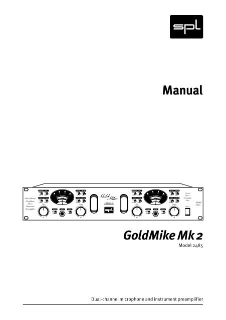
<strong>GoldMike</strong> <strong>Mk</strong> 2<br />
Model 2485<br />
Dual-channel microphone and instrument preamplifier
<strong>Manual</strong> <strong>GoldMike</strong> MK2 Model 2485<br />
Version 1.2 – 12/2005<br />
Designer: Ruben Tilgner<br />
This user's guide contains a description of the product. It in<br />
no way represents a guarantee of particular characteristics<br />
or results of use. The information in this document has been<br />
carefully compiled and verified and, unless otherwise stated<br />
or agreed upon, correctly describes the product at the time of<br />
packaging with this document.<br />
Sound Performance Lab (SPL) continuously strives to improve<br />
its products and reserves the right to modify the product<br />
described in this manual at any time without prior notice. This<br />
document is the property of SPL and may not be copied or reproduced<br />
in any manner, in part or fully, without prior authorization<br />
by SPL.<br />
SPL electronics GmbH<br />
Sohlweg 55, 41372 Niederkruechten<br />
Germany<br />
Tel. +49 (0)2163 983 40<br />
Fax +49 (0)2163 983 420<br />
Email: info@soundperformancelab.com<br />
Website: www.soundperformancelab.com<br />
SPL USA<br />
EMail: www.spl-usa.com<br />
Website: info@spl-usa.com<br />
© 2005 SPL electronics GmbH. All rights reserved. Names of other companies<br />
and their products are trademarks of their respective owners.<br />
2 <strong>GoldMike</strong> MK2
Contents<br />
Introduction ................................................................... 4<br />
Before You Begin ............................................................ 5<br />
Rear Panel/Connections ................................................. 6<br />
Wiring ......................................................................... 6<br />
General advices ........................................................... 7<br />
Mic Input 1/2, Line In 1/2, Inserts 1/2 ........................... 8<br />
Outputs 1/2, GND Lift .................................................. 9<br />
Front Panel/Connections ............................................... 9<br />
Instr. Input 1/2 ............................................................. 9<br />
Control Elements ............................................................ 10<br />
Power, Gain, About Gain Adjustments .......................... 10<br />
Output, Phantom ........................................................ 11<br />
Phase, Pad, Hi Pass .................................................... 12<br />
Flair, Tube Amp, About Tube Amping ............................ 13<br />
Limiter ........................................................................ 15<br />
VU-Cal, Source, Display, VU-Meter ............................... 16<br />
48 V LED, Clip LED, Limit LED, AD OVL LED .................... 17<br />
Technology .................................................................... 18<br />
Solid State and Tube Stages, Output Stage .................. 18<br />
Instrument Input, Relays, Foil Condensers ................... 19<br />
Power Supply ................................................................. 20<br />
Options (A/D Converter and Lundahl Transformers) ........ 21<br />
Specifications/Dimensions & Weight ............................ 23<br />
Guarantee ...................................................................... 24<br />
Notes ............................................................................. 25<br />
<strong>GoldMike</strong> MK2 3
Introduction<br />
The <strong>GoldMike</strong> MK2 is the result of all our experience and<br />
knowledge from its successful predecessor and represents an<br />
improved, more flexible and more modern version.<br />
We have added technologies that have already proven to<br />
provide superior tonal results in other SPL products. For<br />
example, the instrument input is designed around a class A<br />
impedance converter which premiered in the SPL GainStation<br />
preamp.<br />
A significant contribution to the success of the predecessor<br />
was the hybrid preamplifier concept. It combines transistor and<br />
tube preamplifier stages and specifically utilizes their technological<br />
and sonic advantages: the efficiency and low noise of a<br />
discrete transistor stage is enriched with musical coloration of<br />
a tube stage.<br />
The transistor stage is composed of single transistors in a class<br />
A design. The circuitry is fully discrete, and each transistor<br />
is completely optimized for its specific task. You will not find<br />
any integrated circuits in this preamplifier stage because they<br />
cannot be optimized for this specific application to the degree<br />
we aimed for. This all new discrete class A transistor stage is<br />
a genuine innovation in the entire preamplifier market at this<br />
price level.<br />
The degree of tube pre-amplification is no longer the fixed +6<br />
dB value of its predecessor. The <strong>GoldMike</strong> MK2 sports the selection<br />
of three different tube pre-amplifications: +6 dB remains<br />
the standard complemented by +12 dB and +18 dB. This allows<br />
creative variety with the tube saturation and limiting effects.<br />
We have also added an extra setting to the popular Flair circuitry<br />
to give more flexibility to the presence improvement.<br />
Because the <strong>GoldMike</strong> MK2 is a dual channel preamplifier,<br />
its channel separation is of fundamental importance for the<br />
stereo image. Therefore the print-board layout is symmetrically<br />
mirrored around the power supply in the center from<br />
channel 1 to channel 2. This results in an identical signal flow to<br />
supporting a naturally balanced stereo image. Additionally the<br />
print-board provides extra-large ground areas maximizing the<br />
shielding against crosstalk and interference.<br />
4 <strong>GoldMike</strong> MK2
IMPORTANT: Before you operate your <strong>GoldMike</strong> MK2, first<br />
check carefully whether the local voltage setting corresponds<br />
to the switch setting on the rear panel!<br />
Before You Begin<br />
If not, and the voltage is in one way or another, incorrect, you<br />
will either experience an immediate fuse burn through (if the<br />
setting is lower than the supplied power) or, if the power is<br />
110-120 V at a 220-240 V input switch setting, the <strong>GoldMike</strong> MK2<br />
will simply not function correctly.<br />
Moreover, make sure you remove the power plug from your<br />
<strong>GoldMike</strong> MK2 before changing this switch setting!<br />
VOLTAGE<br />
220 – 240 V~50 Hz<br />
110 – 120 V~60 Hz<br />
VOLTAGE<br />
Always turn volume down or mute your speakers when<br />
connecting or repatching audio cables to avoid damage to your<br />
speakers and ears.<br />
It makes good sense to think about where you place the unit<br />
before connecting it. It should be positioned so that you can<br />
easily reach it, but there are other considerations. Try not to<br />
place it near heat sources or in direct sunlight, and avoid exposure<br />
to excessive vibrations, dust, heat, cold or moisture. It<br />
should also be kept away from transformers, motors, power<br />
amplifiers and digital processors. In addition, please:<br />
• Do not open the case. You may risk very dangerous electric<br />
shock and damage to your equipment.<br />
• Leave repairs and maintenance to a qualified service technician.<br />
Should foreign objects fall inside the case, contact your<br />
authorized dealer or support person.<br />
• To avoid electric shock or fire hazards, do not expose your unit<br />
to rain or moisture.<br />
• In case of lightning, unplug the unit. Always unplug the cable<br />
by pulling on the plug only; never pull on the cable.<br />
• Never force a switch or knob.<br />
• Use a soft, lint-free cloth to clean the case, if necessary<br />
together with an acid-free cleaning oil. Avoid any cleaning<br />
agents as they may damage the surfaces of the unit.<br />
<strong>GoldMike</strong> MK2 5
Rear Panel/Connections<br />
Wiring<br />
Optional A/D converter, model 2376<br />
S/P-DIF signal<br />
for external synchronization<br />
S/P-DIF signal to DAW,<br />
HD recorder, etc.<br />
SPL electronics GmbH<br />
Niederkrüchten, Germany<br />
www.soundperformancelab.com<br />
MADE IN GERMANY<br />
Sound Performance Lab<br />
<strong>GoldMike</strong> 2<br />
4860000<br />
SERIAL NUMBER<br />
220 – 240 V~50 Hz: 315 mA slow<br />
110 – 120 V~60 Hz: 630 mA slow<br />
FUSE RATING<br />
24/96 AD<br />
Converter<br />
Model<br />
2376<br />
SAMPLE RATE<br />
44,1<br />
48<br />
x2<br />
SYNC INPUT<br />
SYNC<br />
LOCK<br />
DIGITAL OUTPUTS<br />
SPDIF SPDIF OPTICAL<br />
INPUT OUTPUT OUTPUT<br />
Made in<br />
Taiwan<br />
XLR Wiring:<br />
Pin 1 = GND, Pin 2 = (+), Pin3 = (–)<br />
TRS Jack Wiring:<br />
Tip = (+), Ring = (–), Sleeve = GND<br />
Mono Jack Wiring:<br />
Tip = (+), Sleeve = GND<br />
MIC INPUT 1 LINE IN 1<br />
TRS Jacks: Balanced +4dB<br />
XLR &TRS Jack: Balanced +4dB<br />
Use Mono Jacks for Unbal. Operation<br />
Use Mono Jacks for Unbal. Operation<br />
220 – 240 V~50 Hz<br />
SEND<br />
RETURN<br />
110 – 120 V~60 Hz<br />
WARNING<br />
XLR &TRS Jack: Balanced +4dB<br />
TRS Jacks: Balanced +4dB<br />
TO REDUCE RISK OF FIRE OR ELECTRIC SHOCK DO<br />
Use Mono Jacks for Unbal. Operation<br />
Use Mono Jacks for Unbal. Operation<br />
NOT EXPOSE THIS UNIT TO RAIN OR MOISTURE.<br />
DISCONNECT MAINS BEFORE REMOVING COVER.<br />
RETURN<br />
SEND<br />
THIS EQUIPMENT MUST BE EARTHED.<br />
INSERT 1<br />
OUTPUTS 1<br />
GND LIFT<br />
VOLTAGE<br />
OUTPUTS 2<br />
INSERT 2<br />
LINE IN 2 MIC INPUT 2<br />
Mono Jack:<br />
Unbal. 0dB<br />
Mono Jack:<br />
Unbal. 0dB<br />
CAUTION<br />
RISK OF ELECTRIC SHOCK<br />
DO NOT OPEN<br />
MIC INPUT 2 LINE IN 2<br />
INSERT 2<br />
OUTPUTS 2 VOLTAGE AVIS: RISQUE DE CHOC ÉLECTRIQUE - NE PAS OUVRIR<br />
GND LIFT<br />
OUTPUTS 1<br />
INSERT 1<br />
LINE IN 1 MIC INPUT 1<br />
Effects (EQs etc.) Converter, recorder, console<br />
Line signals* Microphone<br />
PUSH<br />
2 1<br />
3<br />
Pin wiring of<br />
XLR mic inputs<br />
1=Ground, 2=hot(+), 3=cold(-)<br />
1 2<br />
3<br />
Pin wiring of<br />
XLR outputs<br />
1=Ground, 2=hot(+), 3=cold(-)<br />
Pin wiring<br />
of TRS connectors<br />
Tip=hot(+), Ring=cold(-), Sleeve=Ground<br />
* For signals with impedances lower than 1kOhms, i. e. D/A converters, synths, samplers.<br />
Instruments with impedances above 1kOhms are to be connected to the instrument input on the front (see input descriptions on pages 8 and 9).<br />
6 <strong>GoldMike</strong> MK2
General Advices<br />
Rear Panel/Connections<br />
Again, while the <strong>GoldMike</strong> MK2’s housing is EMV-proof and<br />
protects against HF-interference, placement of the unit is very<br />
important since it amplifies microphone signals as well as other<br />
unwanted signals. Before connecting the <strong>GoldMike</strong> MK2 or any<br />
other equipment turn off all power.<br />
IMPORTANT: Adjust the voltage setting on the back so that it<br />
corresponds with your local power conditions.<br />
The following graph shows the correct wiring for connecting<br />
unbalanced signals to the balanced XLR connectors:<br />
VOLTAGE<br />
220 – 240 V~50 Hz<br />
110 – 120 V~60 Hz<br />
VOLTAGE<br />
balanced<br />
Output<br />
unbalanced<br />
1 2<br />
3<br />
1 2<br />
3<br />
1GND<br />
2hot (+)<br />
3cold (-)<br />
The Line Input connector is designed for unbalanced signals<br />
only.<br />
The TRS output connectors (see “Outputs“ on page 9) can be<br />
operated both with balanced and unbalanced wiring. Simply<br />
use a mono 1/4" plug for unbalanced operation.<br />
<strong>GoldMike</strong> MK2 7
Rear Panel/Connections<br />
MIC INPUT 1<br />
MIC INPUT 1<br />
Mic Input 1/2<br />
Dynamic, condenser or tube microphones can be connected to<br />
the Mic inputs. The 48 V switch provides the phantom power<br />
necessary for some microphones (see also “Control Elements/<br />
Phantom“ on page 11).<br />
Alternatively the <strong>GoldMike</strong> MK2 can be equipped with optionally<br />
available input transformers from Lundahl (see “Lundahl<br />
Transformers“ on page 22).<br />
LINE IN 1<br />
Mono Jack:<br />
Unbal. 0dB<br />
LINE IN 1<br />
Line In 1/2<br />
The unbalanced Line Inputs are dedicated to high-impedance,<br />
high-level signals such as A/D converters, synthesizers<br />
or samplers with an impedance of less than 1 kOhm. Signals<br />
with an impedance of above 1 kOhm, e. g. instruments like<br />
E bass, acoustic guitars with pickups or Fender Rhodes must be<br />
connected to the Instrument Input on the front panel.<br />
The max. input level of the Line Inputs is +23 dB.<br />
IMPORTANT: The Line Input is deactivated as long as an instrument<br />
is plugged into Instrument Input jack on the front. We<br />
recommend connecting the Line Input to a patchbay if sources<br />
need to be changed regularly.<br />
RETURN<br />
INSERT 1<br />
TRS Jacks: Balanced +4dB<br />
Use Mono Jacks for Unbal. Operation<br />
INSERT 1<br />
SEND<br />
Inserts 1/2<br />
The balanced TRS Insert connectors (Send and Return) are used<br />
to integrate further units (EQs, compressors, limiters, effects ...)<br />
into the signal path of the <strong>GoldMike</strong> MK2. The Send connector is<br />
placed behind the tube stage and can also be used as direct out<br />
(without output level control). The Return connector is located<br />
in front of Limiter and Output control which allows to control<br />
the output level, e. g. for precise drive level of following A/D<br />
converters.<br />
8 <strong>GoldMike</strong> MK2
Rear Panel/Connections<br />
Outputs 1/2<br />
The preamplifier signals are fed to these electronically balanced<br />
outputs. Alternatively the <strong>GoldMike</strong> MK2 can be equipped with<br />
optionally available transformer outputs from Lundahl (see<br />
“Lundahl Transformers” on page 22).<br />
OUTPUTS 1<br />
XLR &TRS Jack: Balanced +4dB<br />
Use Mono Jacks for Unbal. Operation<br />
OUTPUTS 1<br />
Since the XLR and 1/4 inch TRS connectors are wired in parallel,<br />
an unbalanced connection at one connector will cause unbalanced<br />
operation in its parallel connector, e.g. if a mono 1/4 inch<br />
plug is inserted into the 1/4 inch jack, the corresponding XLR<br />
socket will also operate unbalanced.<br />
GND Lift<br />
The GND Lift switch separates internal ground from chassis<br />
ground. The switch can be activated to eliminate ground loop<br />
humming which may occur if the <strong>GoldMike</strong> MK2 is connected to<br />
units with a different ground potential.<br />
GND LIFT<br />
GND LIFT<br />
The switch should normally be in the GND position to maintain<br />
the shielding effect of the metal housing for internal<br />
<strong>GoldMike</strong> MK2 electronics.<br />
Front Panel/Connections<br />
Instr. Input 1/2<br />
INSTR.<br />
The Instrument input jack is placed on the front panel for easy<br />
access. It should be used to connect instruments like E-bass,<br />
electric guitars, acoustic guitars with pick-ups, etc.<br />
The Instrument input features a 1 MOhm (one Mega Ohm) input<br />
impedance.<br />
IMPORTANT: As long as an instrument is plugged into front<br />
Instrument input, the rear panel Line Input is deactivated.<br />
<strong>GoldMike</strong> MK2 9
Control Elements<br />
Power<br />
Power<br />
You guessed that: with the Power switch the <strong>GoldMike</strong> MK2<br />
is activated, verified by the illuminating switch. Please read<br />
“Before You Begin” on page 5 before throwing in for the first<br />
time.<br />
Gain<br />
24 27 29<br />
22 3235<br />
21<br />
20<br />
38<br />
19<br />
18<br />
17<br />
49<br />
16 54<br />
15 60<br />
66<br />
14<br />
dB<br />
41<br />
44<br />
Gain<br />
The Gain control determines the level of pre-amplification.<br />
The pre-amplification values cover a range from +14dB up to +<br />
67dB.<br />
IMPORTANT: If Lundahl input transformers are fitted the scale<br />
values are to be increased by up to +14dB (depending upon<br />
microphone in use).<br />
About Gain Adjustments<br />
Amplifying a signal to line level should principally be done solely<br />
with the Gain control. The Output level control is used to adjust<br />
the proper drive level for subsequent equipment.<br />
The VU Cal switch should be set to 0dB (Note: The VU displays<br />
the pre-amplification, not the output level).<br />
Now turn up the Gain control until the VU shows values between<br />
0 dB and +3 dB. There is still enough headroom to prevent clipping<br />
at varying input levels. Note that the VUs show average<br />
levels instead of peak levels (which can be up to 10 dB higher).<br />
Thus, in recording high-level signals such as snare and kick,<br />
etc. it may be necessary to engage the Pad switch.<br />
You can drive the Gain harder if you know that unexpected input<br />
level changes are unlikely to occur. Watch if the Clip-LED indicates<br />
clipping in the preamplifier stages and set the VU Cal to<br />
-10dB to adjust the VU meter range accordingly.<br />
IMPORTANT: The Clip-LED should never illuminate during a<br />
recording session to avoid distorted results.<br />
10 <strong>GoldMike</strong> MK2
Control Elements<br />
Output<br />
This potentiometer adjusts the output level for devices<br />
following in the chain or to the converter. The Output Level<br />
control allows an additional +6 dB of amplification or -26 dB of<br />
reduction. Output level values set with the output level control<br />
are not indicated by the VU meters, which indicate pre-amplification<br />
levels before this final stage.<br />
Output<br />
-10 -9 -8<br />
-12 -6<br />
-14<br />
-5<br />
-16<br />
-2.5<br />
-18<br />
0<br />
-20<br />
2<br />
-22<br />
3.5<br />
-24 5<br />
-25 5.5<br />
-26 6<br />
dB<br />
Phantom<br />
The <strong>GoldMike</strong> MK2 provides 48 Volt phantom power for microphones<br />
requiring external current (generally condenser microphones).<br />
Such microphones are dependent upon a clean, consistent<br />
and noise-free power supply for optimal operation and<br />
audio quality. The <strong>GoldMike</strong> MK2 continuously delivers precisely<br />
48 V and a maximum of 14 mA, which will power all microphones.<br />
PHANTOM<br />
48V<br />
Off<br />
VERY IMPORTANT: All microphones with balanced, groundfree<br />
outputs, including tube microphones, can be used with<br />
the phantom power activated. Phantom power should only be<br />
activated when using microphones that require it. Please be<br />
sure to deactivate phantom power with all other microphones.<br />
Unbalanced microphones may only be used with phantom<br />
power deactivated.<br />
PLEASE ALWAYS FOLLOW THESE INSTRUCTIONS TO ACTIVATE<br />
AND DEACTIVATE PHANTOM POWER: First connect the microphone<br />
to the <strong>GoldMike</strong> MK2, then activate phantom power. When<br />
finished, first deactivate phantom power and wait at least until<br />
the 48V LED has gone out completely before disconnecting the<br />
microphone! This ensures residual current will be discharged.<br />
Furthermore, when changing microphones, you should wait<br />
until the 48V LED is completely dark before re-patching. THE<br />
GOLDMIKE MK2’S INPUT STAGES CAN BE DAMAGED IF YOU<br />
IGNORE THESE PROCEDURES!<br />
<strong>GoldMike</strong> MK2 11
Control Elements<br />
PHASE<br />
Rev.<br />
Nor.<br />
Phase<br />
The phase reverse function reverses the polarity of the microphone<br />
signal, inverting the phase (by 180°) to correct phaseinverted<br />
signals caused by multiple signal sources. A voiceover<br />
artist, for example, hears himself during recording through<br />
the headphones and simultaneously through the bones in his<br />
head. Phase inversion will cause an unnatural sound, and<br />
even minimal variations in distance to the microphone will<br />
cause drastic variations in the sound. Phase inversion is also<br />
commonly encountered when using multiple microphones on<br />
a single sound source. We recommend checking for correct<br />
polarity before each recording.<br />
PAD<br />
dB<br />
-20<br />
Off<br />
HI PASS<br />
Hz<br />
50<br />
Off<br />
Pad<br />
The Pad switch attenuates the input by -20dB. High-level input<br />
signals can be attenuated in order to prevent overdriving the<br />
preamplifier. The <strong>GoldMike</strong> MK2 has a minimum pre-amplification<br />
of +14 dB. But with miked signals such as drums and brass<br />
or high level line input signals, this may already be too much.<br />
Engaging Pad attenuates the minimum pre-amplification (Gain<br />
control fully counter clockwise) to -6 dB, thus providing a useful<br />
Gain control range for loud input signals.<br />
Hi Pass<br />
This switch activates the integrated high-pass filter, which<br />
operates from 50 Hz downwards with 12 dB/octave (often called<br />
a “rumble filter“). The filter is entirely passive, avoiding additional<br />
active circuitry that could potentially degrade the signal,<br />
and cuts 6 dB pre- and 6 dB post-solid-state stage pre-amplification<br />
to prevent the amplification of unwanted low-frequency<br />
signal components.<br />
12 <strong>GoldMike</strong> MK2
Control Elements<br />
Flair<br />
As with its predecessor, the model 9844 <strong>GoldMike</strong>, the<br />
<strong>GoldMike</strong> MK2 features our sound-optimizing Flair circuitry. This<br />
circuitry takes advantage of a combined coil and tube filtering<br />
to enhance signal presence. In comparison to simple EQ manipulation,<br />
this intensified presence sounds very natural and unobtrusive,<br />
and is particularly suited for optimizing the overtones<br />
in voice and acoustic instruments.<br />
FLAIR<br />
High<br />
Off<br />
Med<br />
With Flair processing, a signal gains richness in detail, presence,<br />
intelligibility (for vocals), and in an increased ability to cut<br />
through in a mix. In such mixes, a Flair-processed signal stands<br />
out without resort to conventional processing often unsuited to<br />
the task, saving both time and a need for artificial processing.<br />
Flair works through an emphasis in the 1.5-20 kHz range centered<br />
around 6 kHz.<br />
The <strong>GoldMike</strong> MK2 provides for two different settings, with a<br />
“High” setting of +2.5 dB and a “Med.” with +1.5 dB emphasis.<br />
An Off setting allows you to deactivate the Flair circuit entirely.<br />
Tube Amp<br />
The Tube Amp switch varies the degree of tube pre-amplification<br />
added to the discrete class A pre-amplification, which itself<br />
is set with the Gain control. The switch allows for three settings:<br />
+6 dB (standard) +12 dB and +18 dB. In each setting the output<br />
level of the tube is automatically accomodated so that output<br />
levels do not have to be recalibrated when the tube is driven<br />
hotter. This allows for instant comparison between varying<br />
Tube Amp values and their sonic effects (also refer to “About<br />
Gain Adjustments” on page 10).<br />
TUBE AMP<br />
18 dB<br />
6<br />
12<br />
<strong>GoldMike</strong> MK2 13
Control Elements<br />
Using the Tube Amp switch<br />
Engaging the Tube Amp switch tends to have a significant impact<br />
on the overall sound, as it directly changes the sonic character<br />
of the tube. The higher the Tube Amp value, the more you will<br />
have tube saturation and harmonic distortion, in addition to<br />
limiting effects. These effects can be used creatively to shape a<br />
sound.<br />
Subtle overdrive of the tube creates moderate saturation effects<br />
and relatively little harmonic distortion—the limiting effects are<br />
already present. If this behavior is desired, try a +12 dB setting<br />
with the Gain control also set to moderate pre-amplification.<br />
For a more dramatic tube sound the Tube Amp switch should<br />
be set to +18 dB. This results in a very audible saturation and<br />
harmonic distortion. The intensity can then be fine-tuned with<br />
the Gain control: the more gain, the more phatt ...<br />
Tube limiting controls peaks in a musically advantageous<br />
fashion and can be used to co mplement the Limiter. The tube<br />
limiting is not as accurate and sonically neutral as the Peak-<br />
Limiter because harmonic tube distortion is added to the<br />
signal.<br />
To fully protect connected converters you should keep the Peak-<br />
Limiter active and monitor the action of the VU meter, the Clipand<br />
Limiter-LED.<br />
14 <strong>GoldMike</strong> MK2
Control Elements<br />
Limiter<br />
The <strong>GoldMike</strong> MK2 offers a peak limiter that operates before<br />
the output level control. This ensures that the limited signal can<br />
be controlled as perfectly as possible for the internal—or an<br />
external—converter.<br />
LIMITER<br />
dB<br />
18<br />
Off<br />
12<br />
The peak limiter operates with special diodes that convert signal<br />
peaks into a pleasant-sounding saturation. Depending on the<br />
signal, this allows for an effective and subtle level limiting.<br />
Diode-based limiting works very quickly (much faster than<br />
common VCA- or FET-based limiters), reliably limits even microsecond-long<br />
transients, and is very effective for drums and<br />
percussion. The peak limiter also enables maximum loudness.<br />
Its degree of activity is displayed via the Limit LED.<br />
The peak limiter is ideally suited to limit signals with a high<br />
degree of transients such as snare, kick, brass and other percussion<br />
instruments. Sine-wave like signals such as vocals, flute<br />
and layer sounds can also be protected, but the degree of<br />
increased loudness is limited.<br />
Overdriving the peak limiter will be audible as distortion, an<br />
effect quite similar to overdriving the preamplifier. In order to<br />
avoid irritations please monitor the Clip-LED. If the Clip-LED<br />
is not illuminating, the distortion is coming from the peak<br />
limiter. In that case increase the Threshold value. There are two<br />
threshold values to choose from: +12 dB and +18 dB. Limiting<br />
is less when selecting the +18dB threshold and intensified<br />
when choosing +12 dB. If the Limit LED illuminates constantly,<br />
you should select the +18 dB setting or reduce the Gain control<br />
setting (also see “Limit-LED“ on page 17).<br />
After setting the Limiter you can adjust the output level signal<br />
for equipment coming next in your chain. If you have opted for<br />
the internal A/D converter, you should keep an eye on the A/D<br />
Ovl LED. When this LED illuminates, the internal A/D converter<br />
is clipping. Reduce the output level until the A/D Ovl LED goes<br />
out. If external converters are used, check their clipping LEDs<br />
when setting the output level.<br />
This placement of the limiter before the output level control<br />
helps exploit the headroom of A/D converters to the maximum<br />
while at the same time offering a signal peak safety margin.<br />
<strong>GoldMike</strong> MK2 15
%<br />
0<br />
Control Elements<br />
VU CAL<br />
-10 dB<br />
0<br />
VU-Cal<br />
The display range of the VU meter can be shifted using the -10dB<br />
VU Cal switch position.<br />
If the VU Cal switch is set to its 0 dB position and the output<br />
level control is also set to 0dB with the limiter switched off,<br />
the output level will effectively be 0 dBu. With the VU Cal set to<br />
-10 dB the 0 dB mark on the VU meter will represent a +10 dBu<br />
output level. This way you can display audio level higher than<br />
+6 dB (up to +16 dB) on the VU meter.<br />
SOURCE<br />
Instr.<br />
Line<br />
Mic<br />
Source<br />
This switch allows you to select between the Mic and Line/<br />
Instrument inputs. All inputs can remain connected at all times,<br />
regardless of which input is selected. You can choose the Line<br />
input as source as long as the Instrument input is not being<br />
used.<br />
If you engage this switch first after powering up the unit, there<br />
can be a noticeable pop due to the discharge of residual current.<br />
This is normal and no cause for concern.<br />
Clip Limit<br />
48 V<br />
AD OVL<br />
Sound Performance<br />
7 5 3 1 0 3 5<br />
20 10 30 50 70 100<br />
VU<br />
1<br />
Lab<br />
Central Display<br />
The display consists of all status LEDs and the VU meter so that<br />
all important information can be viewed without distraction.<br />
Display/VU Meter<br />
The VU meter shows the internal gain level (not the output level).<br />
Its scale ranges from -20 dB to +6 dB. If needed, the sensitivity<br />
can be reduced by 10 dB, which extends the scale to +16 dB (see<br />
“VU Cal” above). Please refer as well to the information “About<br />
Gain Adjustments” on page 10.<br />
16 <strong>GoldMike</strong> MK2
Control Elements<br />
Display/48 V LED<br />
The 48V-LED indicates that the phantom power supply is activated.<br />
The 48V-LED will slowly dim before going out to indicate<br />
that it takes some time for residual current to discharge.<br />
VERY IMPORTANT: The connection between microphone<br />
and <strong>GoldMike</strong>MK2 should not be disengaged before the LED<br />
is completely dark! To avoid damages, please note also the<br />
phantom power supply usage information on page 11.<br />
Display/Clip LED<br />
The Clip LED shows internal clipping of the <strong>GoldMike</strong> MK2. To<br />
avoid distorted results the Clip-LED should never illuminate<br />
during a recording session (also refer to “About Gain<br />
Adjustments” on page 10).<br />
Display/Limit LED<br />
The Limit LED shows the activity of the Peak Limiter. The Limiter<br />
threshold can be set to 12 or 18 dBu, and for optimal operation,<br />
should only illuminate in very short intervals. If the LED is illuminating<br />
too often even at the 18 dB position, you must reduce the<br />
Gain value (and possibly afterwards, further adjust the output<br />
level) to achieve unobtrusive results—unless, of course, you<br />
really want this effect (also see the chapter “Limiter” on page<br />
15).<br />
Display/AD OVL LED<br />
This LED is only active when the optional AD converter module<br />
is installed. It displays clipping in the internal AD converter and<br />
illuminates at approximately 0.5 dB before 0 dBfs. This LED<br />
should never illuminate when using the internal converter. If it<br />
does, the output level must be reduced accordingly. For further<br />
information on the converter module see page 21, “Optional<br />
Digital Output: 24/96 AD converter, model 2376”. With external<br />
converters in use, please always check their internal clipping<br />
displays.<br />
<strong>GoldMike</strong> MK2 17
Technology<br />
Solid state and tube stages<br />
The solid stage preamp section is based on a fully discrete,<br />
balanced instrument amplifier and operates 12 single transistors<br />
in class A mode. A sophisticated circuitry ensures a nearly<br />
constant frequency response at any gain level. With an impressive<br />
slew rate of more than 200V/µs the solid stage is capable to<br />
amplify highest frequencies and fastest transients with almost<br />
no distortion, which is crucially important to achieve a realistic<br />
sound experience. Coupling condensers were used as sparingly<br />
as possible to avoid their inherent disadvantages such as<br />
diffuse sound, slurring and loss of dynamics. To eliminate DC<br />
artifacts, these are replaced by servo circuits operating outside<br />
of the audio signal paths.<br />
An op-amp subsequently converts the instrument amplifier’s<br />
output signal into an unbalanced one, which is then fed to the<br />
tube. Here an additional +6 dB tube amplification is added,<br />
switchable to +12 and +18 dB with the Tube Amp function.<br />
The tube type—a Sovtek 12 AX7 LPS—was also selected after<br />
extensive measurements and listening tests. This tube type<br />
outclasses the standard 12 AX 7 by far and delivers an open,<br />
transparent sound, excellent noise values and is especially reliable.<br />
An impedance converter adapts the tube’s high-impedance<br />
signal to the following stages.<br />
Output Stage<br />
The output stage can drive very long connections (depending on<br />
cable capacities, up to several hundred yards). The maximum<br />
output level is at +26 dBu, allowing plenty of headroom to drive<br />
subsequent converters.<br />
18 <strong>GoldMike</strong> MK2
Technology<br />
Class A Instrument Input<br />
The Instrument Input is a fully discrete impedance converter<br />
that also operates in class A mode. It is based on a low-noise<br />
field effect transistor that, due to its extremely high input impedance,<br />
is especially well suited to this task.<br />
Relay switching<br />
In order to ensure the shortest possible signal paths, nearly all<br />
switching functions are handled by optimally positioned, encapsulated<br />
relays with gold-plated contacts (the switches themselves<br />
only trigger the relays). Since resistors also greatly affect<br />
audio quality, the entire audio signal path utilizes painstakingly<br />
selected resistors with 0.1 % tolerance.<br />
Foil condensers<br />
The op-amp circuits use premium FKP foil condensers, which<br />
sound much more open than ceramic types and provide more<br />
natural dynamic response.<br />
<strong>GoldMike</strong> MK2 19
Power Supply<br />
In the case of the power supply, no expense was spared. After<br />
all, the power supply is one of the primary factors in the audio<br />
quality and overall sound of any device. Just like the best coffee<br />
beans in the world will not produce a good cup of coffee with<br />
poor water, the best circuits can’t produce a great sound with<br />
unreliable, inconsistent voltages. The transformer delivers<br />
three different voltages, each of which is separately screened<br />
and regulated: 250 V anode current for the tube, 48 V for<br />
phantom power and 2 x 15 V for the audio signal path.<br />
Critical currents are stabilized via a 100-nF MKP foil condenser,<br />
to ensure sufficient current for even the shortest impulses.<br />
The transformer is encompassed by double shielding to keep<br />
magnetic stray fields to an absolute minimum.<br />
An AC power cord is included for connection to the standard<br />
3-prong IEC connector. The transformer, power cord and IEC<br />
connector are VDE, UL and CSA approved. The AC fuse is rated<br />
at 315 mA for 220/240 V and 630 mA for 110/120 V.<br />
20 <strong>GoldMike</strong> MK2
Options<br />
• 24-Bit/96kHz A/D converter (after sale upgrades can be done<br />
by clients).<br />
• Lundahl input and output transformers (after sale upgrades<br />
by authorized service personnel or SPL only).<br />
24/96 A/D Converter<br />
24/96 AD<br />
Converter<br />
SAMPLE RATE<br />
SYNC INPUT<br />
SYNC<br />
LOCK<br />
DIGITAL OUTPUTS<br />
Model<br />
2376<br />
44,1<br />
48<br />
x2<br />
SPDIF SPDIF OPTICAL<br />
INPUT OUTPUT OUTPUT<br />
Made in<br />
Taiwan<br />
The optional 24/96 Converter module (model 2376) provides a<br />
digital output for the <strong>GoldMike</strong> MK2 in the form of an S/P-DIF<br />
output with RCA and optical connectors (in parallel). The<br />
converter transmits 24-bit signals.<br />
The module is based on a 24-bit converter by AKM® with a<br />
variable sample rate of up to 96 kHz. All common sample rates<br />
can be selected (see below). Highly accurate quartz oscillators<br />
ensure a clean, low-jitter master clock.<br />
Sample Rate<br />
The 24/96 AD converter module allows you to select among the<br />
four most common sample rates of 44.1, 48, 88.2 and 96 kHz.<br />
Using the 44.1/48 button, select one of the two basic sample<br />
rates (out: 44.1 kHz; in: 48 kHz). The x2 button doubles these<br />
sample rates to select 88.2 or 96 kHz respectively.<br />
Dig. Out<br />
The converted S/P-DIF signal is routed in parallel to the RCA<br />
and optical outputs. The signal is in professional format with no<br />
sample rate data in the status block.<br />
<strong>GoldMike</strong> MK2 21
Options<br />
Sync Input<br />
The SYNC input allows you to feed an external signal into<br />
the converter to control the sample rate (since this is an AD<br />
converter, the SYNC Input is no audio signal input). Connect an<br />
S/P-DIF output from your master source (e.g. sound card) to the<br />
SYNC input. The AD converter will automatically switch to the<br />
same sample rate that is received. The 2376 is not equipped to<br />
accept Word Clock synchronization.<br />
The yellow Sync Lock LED illuminates when a valid sync signal<br />
is present at the Sync input and the converter is automatically<br />
synchronized to the external sample rate.<br />
To prevent interference, the internal oscillators are automatically<br />
disabled when an external clock signal is present. If the<br />
sync signal is no longer present (e.g. in the case of a dropout),<br />
the converter automatically reverts to the sample rate selected<br />
via the converter’s control switches.<br />
Lundahl-Transformers<br />
Transformers have characteristics usually associated with other<br />
analog components like tubes or coils—they sound “warmer”,<br />
and punchier especially in the bass and mid area and deliver<br />
improved presence without boosting the top end. One reason<br />
for this is that transformers cancel out a large amount of odd<br />
harmonics (those portions of an audio signal that sound harsh<br />
to human ears).<br />
Equipping the <strong>GoldMike</strong> MK2 with transformer-based inputs<br />
and outputs means you benefit from their unique characteristics.<br />
IMPORTANT: The <strong>GoldMike</strong> MK2’s input transformer delivers up<br />
to +14 dB of additional passive gain, which must be added to<br />
the printed values.<br />
22 <strong>GoldMike</strong> MK2
Specifications<br />
Frequency response<br />
Input impedances<br />
Microphone, XLR<br />
Line In, TRS<br />
Instr. In TRS<br />
‹10 Hz to 90 kHz (-3 dB)<br />
2,8 kOhm<br />
10 kOhm<br />
1 MOhm<br />
Output impedances XLR and TRS connectors<br />
50 Ohm<br />
THD+N<br />
Input level<br />
Gain<br />
-30 dBu 30 dBu 0,016 %<br />
-40 dBu 40 dBu 0,017 %<br />
-50 dBu 50 dBu 0,022 %<br />
-60 dBu 60 dBu 0,048 %<br />
Noise, A weighted, R=40Ohm<br />
Gain<br />
30 dB -91,2 dBu<br />
40 dB -86,6 dBu<br />
50 dB -78,7 dBu<br />
60 dB -69,3 dBu<br />
Dynamic range, 30 dB Gain<br />
E.I.N<br />
Max. Input level<br />
Mikrophone, XLR<br />
Mikrophone, XLR +PAD<br />
Line In, TRS connector<br />
Instr. In TRS connector<br />
Instr. In TRS connector +PAD<br />
Max. output level<br />
Balanced, XLR+TRS<br />
Unbalanced, XLR+TRS<br />
110 dB<br />
128 dBu<br />
+7 dBu<br />
+28 dBu<br />
+23 dBu<br />
+7 dBu<br />
+14 dBu<br />
+26,8 dBu<br />
+21,5 dBu<br />
CMRR<br />
1 KHz, Gain 30 dB ›75 dB<br />
10 KHz, Gain 30 dB ›75 dB<br />
Power consumption<br />
Dimensions B x H x T<br />
Weight<br />
25 W<br />
482 x 88 x 210 mm/19.28 x 3.52 x 8.4 in<br />
4,1 Kg/9.02 lbs<br />
Specifications subject to change without notice.<br />
<strong>GoldMike</strong> MK2 23
Guarantee<br />
All SPL products come with a two-year manufacturer’s<br />
guarantee against defects in material or assembly from the<br />
date of purchase.<br />
End users are supported in the two-year guarantee through<br />
their distributor or dealer. In such cases, please contact your<br />
dealer for full guarantee conditions and service.<br />
Direct SPL product support requires product registration.<br />
Please fill out the guarantee card enclosed in the package<br />
legibly in printed letters and send it directly to SPL.<br />
Or use the online registration form that may be reached at<br />
www.soundperformancelab.com (international clients) or<br />
www.spl-usa.com (US clients).<br />
24 <strong>GoldMike</strong> MK2
Notes<br />
...............................................................<br />
...............................................................<br />
...............................................................<br />
...............................................................<br />
...............................................................<br />
...............................................................<br />
...............................................................<br />
...............................................................<br />
...............................................................<br />
...............................................................<br />
...............................................................<br />
...............................................................<br />
...............................................................<br />
...............................................................<br />
...............................................................<br />
...............................................................<br />
...............................................................<br />
...............................................................<br />
...............................................................<br />
...............................................................<br />
<strong>GoldMike</strong> MK2 25
<strong>Manual</strong> <strong>GoldMike</strong> MK2 Model 2485<br />
Rediscover Analog at soundperformancelab.com