JPA-1060 JPA-1120 JTP-10 JCP-10 JCR-10
JPA-1060 JPA-1120 JTP-10 JCP-10 JCR-10
JPA-1060 JPA-1120 JTP-10 JCP-10 JCR-10

Create successful ePaper yourself
Turn your PDF publications into a flip-book with our unique Google optimized e-Paper software.
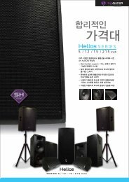
PUBLIC ADDRESS<br />
AMPLIFIER<br />
<strong>JPA</strong>-<strong><strong>10</strong>60</strong><br />
<strong>JPA</strong>-<strong>1120</strong><br />
FM / AM TUNER<br />
<strong>JTP</strong>-<strong>10</strong><br />
CASSETTE DECK<br />
<strong>JCP</strong>-<strong>10</strong><br />
CASSETTE RECEIVER<br />
<strong>JCR</strong>-<strong>10</strong><br />
WWW.JEDIA.COM
SAFETY INSTRUCTIONS<br />
Read all safety instruction before operating the <strong>JPA</strong>-Series.<br />
1. Install equipment as follow conditions.<br />
Install at the place, not bending curved.<br />
Do not install this apparatus in a confined space such as a book<br />
case or similar unit.<br />
The apparatus shall not be exposed to dripping or splashing and<br />
no object filled with liquids, such as vases, shall be place on the<br />
apparatus.<br />
Locate this apparatus away from heat source, such as radiators<br />
or other device that produce heat.<br />
Do not drop objects or spill liquids into the inside of the apparatus.<br />
2. Keep in mind the following when connecting the apparatus.<br />
Connect the apparatus after reading of O/P manuals.<br />
Connect each connection of amplifier perfectly, if not, it maybe<br />
Caused hum, damage, electric shock in case of mis-connecting.<br />
To prevent electric shock, do not open top cover.<br />
Connect the power cord with safety after check of AC power.<br />
The apparatus shall not be exposed to dripping or splashing and<br />
no object filled with liquids, such as vases, shall be placed on<br />
the apparatus.<br />
DISCONNECTING DEVICE FROM MAINS - Appliance inlet is the<br />
disconnecting device. The inlet must remain readily operable.<br />
<br />
<br />
<br />
<br />
<br />
<br />
<br />
<br />
<br />
<br />
<br />
<br />
<br />
<br />
<br />
<br />
<br />
<br />
<br />
<br />
<br />
<br />
This apparatus should be serviced by qualified service person.<br />
<br />
1
U NPACKING & INSTALLATION<br />
Although it is neither complicated to install nor difficult to operate<br />
your amplifier, a few minutes of your time is required to read this<br />
manual for a properly wired installation and becoming familiar with its<br />
many features and how th use them.<br />
Please take a great care in unpacking your set and do not discard<br />
the carton and other packing materials. They may be needed when<br />
moving your set and are required if it ever becomes necessary to<br />
return your set for sevices. Never place the unit near radiator, in front<br />
of heating vents, to direct sun light, in excessive humid or dusty<br />
location to avoid early damage and for your years of quality use.<br />
Connect your complementary components as illustrated in the<br />
following pages.<br />
F EATURES<br />
VERSATILE INPUT ADJUSTMENT<br />
These models can be adjusted the input sensitivity from channel<br />
1~5. Each of CH1~5 is composed of the balanced input and can<br />
be changed the input and connector to phone jack or XLR jack<br />
according to buyer's order.<br />
TELEPHONE INPUT & MUSIC-ON-HOLD(ONLY FOR TUNER)<br />
These models have a function of telephone input and music-on-hold to connect with telephone system.<br />
PRIORITY MUTE<br />
MIC 1, chime and siren have priority to the other signal.<br />
You can adjust mute level as adjusting volume of rear panel.<br />
(except TEL IN & M.O.H)<br />
DIGITAL TUNER(OPTION)<br />
These models, module-type digital tuner has memory function of<br />
18stations.<br />
REMOTE CHIME<br />
You can use conveniently remote control for these models through<br />
the external chime terminal.<br />
ZONE SPEAKER SELECTOR<br />
4 speaker selector switches are provided individually or totally.<br />
USE OF EMERGENCY BATTERY<br />
you can operate this models by using emergency battery for<br />
unexpected AC power failure. (Built in DC 24V TERM)<br />
AUTO REVERSE CASSETTE DECK(OPTION)<br />
This is a highly reliable auto reverse cassette deck to allow<br />
continuous playback.<br />
AUTO REVERSE CASSETTE DECK AND FM/AM TUNER(OPTION)<br />
1
PHONO/LINE BASS TREBLE<br />
F RONT PANEL CONTROLS<br />
13<br />
9<br />
<strong>10</strong><br />
11<br />
PUBLIC ADDRESS AMPLIFIER <strong>JPA</strong>-<strong>1120</strong><br />
SP1 SP2 SP3 ALL<br />
LEVEL METER<br />
+2<br />
0<br />
CHIME<br />
SIREN<br />
SPEAKER SELECTOR<br />
-2<br />
-5<br />
-7<br />
-<strong>10</strong><br />
-13<br />
-16<br />
-21<br />
ON<br />
12<br />
CH1<br />
CH2<br />
CH3<br />
CH4<br />
MASTER<br />
POWER<br />
8<br />
0 <strong>10</strong> 0 <strong>10</strong> 0 <strong>10</strong><br />
0 <strong>10</strong> 0 <strong>10</strong><br />
0 <strong>10</strong> 0 <strong>10</strong> 0 <strong>10</strong><br />
ON<br />
OFF<br />
1<br />
7<br />
6<br />
5<br />
2<br />
3<br />
4<br />
1. POWER SWITCH<br />
Pressing this switch to ON will make the power indication LED ON and supply the power th this unit.<br />
2. MASTER VOLUME<br />
This control is used ofr adjusting the volume of fianlly mixed sound.<br />
3. TREBLE<br />
This control is used ofr adjusting the high frequency sound.<br />
4. BASS<br />
This control is used for adjusting the low frequency sound.<br />
5. PHONO/LINE VOLUME<br />
You can adjust the input of phono of line which is selected by the rear panel switch.<br />
6. CH2~4 VOLUME<br />
You can adjust input of MIC or line whichis selected by the rear panel switch of CH2~CH4.<br />
7. CH1 VOLUME<br />
You can adjust the volume level of MIC1.<br />
8. CH1 INPUT JACK<br />
This jack to insert MIC plug in case of employing MIC 1. The signal supplied to the mic is controlled by the volume of MIC1.<br />
9. CHIME SWITCH<br />
Pressing this switch. It will activate 4 tone chime circuitry.<br />
<strong>10</strong>. SIREN SWITCH<br />
Pressing these switches. It will activate constant or wavy siren circuitry.<br />
11. SPEAKER SELECTOR<br />
These switches are used for connecting the output of amplifier to the speaker individually of totally.<br />
12. OUTPUT LEVEL DISPLAY<br />
These displays indicate the output level.<br />
13. BLANK PANEL<br />
You can use this table type amplifier with digital tuner or cassette deck as a module type.<br />
2
R ECEIVER CONTROLS<br />
<strong>10</strong><br />
13<br />
11<br />
9<br />
12<br />
2 8<br />
FM/AM TUNER<br />
EJECT<br />
DIRECTION<br />
PAUSE<br />
F1<br />
CH<br />
AUTO REVERSE<br />
3<br />
CASSETTE RECEIVER<br />
TUNE<br />
B<br />
A<br />
ON AM/FM 1 2 3 4 5 6<br />
0 <strong>10</strong><br />
LEVEL<br />
1<br />
4<br />
7<br />
6<br />
5<br />
1. TUNER ON SWITCH<br />
This switch is used for supplying the power to tuner and display.<br />
2. TUNER DISPLAY<br />
You can confirm the frequency for tuner through this display.<br />
3. TUNER LED<br />
This LED indicates tuning for adsolute of AM and FM signals ensuring minimum distortion and maximum output.<br />
4. BAND SELECTOR FM, AM<br />
This switch is user for selecting FM1, FM2 or AM.<br />
5. UP AND DOWN SWITCH<br />
When these switches are pressed one time, FM/AM frequency is up or down with one step, and in case of<br />
pressing over 2 seconds, the mode will change to "Auto scan".<br />
6. PRESET SWITCH<br />
These switches have be changed 6 kinds address form 1 yo 6, per each band.<br />
If you want memorizing the broadcasting frequency press the switch over 2 seconds.<br />
7. TUNER VOLUME<br />
Adjust volume controller as you want by volume controller.<br />
8. PAUSE BUTTON<br />
A botton to temporary pause the operation in playing.<br />
9. EJECT BUTTON<br />
When you push this button, tape will be come out.<br />
<strong>10</strong>. CASSETTE DOOR<br />
You can start the cassette playback by inserting the cassette into this slot.<br />
11. REW BUTTON<br />
This is fast rewinding button toward .<br />
12. FF BUTTON<br />
It will be fast toward , when pushing it.<br />
When pushing rew button and FF button simultaneously, tape direction will be reverse.<br />
13. DIRECTION LED INDICATOR<br />
This is for indicator for tape direction.<br />
3
T UNER CONTROLS<br />
2 3<br />
4<br />
FM/AM TUNER<br />
AM/FM<br />
1 2 3<br />
ON 4 5 6<br />
0 <strong>10</strong><br />
LEVEL<br />
6<br />
1<br />
5<br />
1. TUNER ON SWITCH<br />
This switch is used for supplying the power to tuner and display.<br />
2. TUNER DISPLAY<br />
You can confirm the frequency of tuner through this display.<br />
3. BAND SELECTOR FM, AM<br />
This switch is user for selecting FM1, FM2 or AM.<br />
4. UP AND DOWN SWITCH<br />
When these switches are pressed one time, FM/AM frequency is up or down with one step, and in case of pressing over<br />
2 seconds, the mode will change to "Auto scan".<br />
5. PRESET SWITCH<br />
These switches have be changed 6 kinds address form 1 yo 6, per each band.<br />
If you want memorizing the broadcasting frequency press the switch over 2 seconds.<br />
6. TUNER VOLUME<br />
You can adjust the volume of FM or AM radio signal.<br />
4
D ECK CONTROLS<br />
2 4<br />
5<br />
AUTO REVERSE<br />
PAUSE<br />
EJECT<br />
Cassette Player Module<br />
DIRECTION<br />
B<br />
A<br />
0 <strong>10</strong><br />
LEVEL<br />
1<br />
2<br />
7<br />
6<br />
1. PAUSE BUTTON<br />
A button to temporary pause the operation in playing.<br />
2. EJECT BUTTON<br />
When you push this button, tape will be come out.<br />
3. CASSETTE DOOR<br />
You can start the cassette playback by inserting the cassette into this slot.<br />
4. REW BUTTON<br />
This is fast rewinding button toward .<br />
5. FF BUTTON<br />
It will be fast toward ,when pushing it.<br />
* When pushing rew button and FF button simultaneously, tape direction will be reverse.<br />
6. DIRECTION LED INDICATOR<br />
This is for indicator for tape direction.<br />
7. VOLUME CONTROLLER<br />
Adjust volume controller as you want by volume controller.<br />
5
R EAR PANEL CONTROLS<br />
5 6<br />
4<br />
3<br />
2<br />
1<br />
16<br />
15<br />
AC220V<br />
DC POWER<br />
24V <strong>10</strong>A<br />
60Hz 295W<br />
DC<br />
T<strong>10</strong>A 250V<br />
FUSE<br />
AC<br />
IMPEDANCE<br />
70V<br />
<strong>10</strong>0V<br />
8<br />
4<br />
T3A 250V<br />
COM<br />
AM<br />
SP1 SP2 SP3<br />
GND<br />
FM 75<br />
300<br />
PRE AMP OUT<br />
AMP IN<br />
GND<br />
M.O.H<br />
LINE<br />
–<strong>10</strong>dB<br />
CHIME<br />
REMOTE<br />
TEL<br />
IN<br />
LINE/PHONO<br />
PHONO<br />
–54dB<br />
MODEL NO.: <strong>JPA</strong>-<strong>1120</strong><br />
PUBLIC ADDRESS AMPLIFIER<br />
OUTPUT POWER: 30W<br />
LINE<br />
<strong>10</strong>dB<br />
MADE IN KOREA<br />
CAUTION<br />
RISK OF ELECTRIC SHOCK<br />
DO NOT OPEN<br />
CH4<br />
MIC<br />
50dB<br />
LINE<br />
<strong>10</strong>dB<br />
CAUTION: TO PREVENTELECTRIC SHOCK DO NOT<br />
REMOVE TOP OR BOTTOM COVERS.<br />
NO USER SERVICEABLE PARTS INSIDE.<br />
WARNING: TO REDUCE THE RISK OF FIRE OR<br />
ELECTRIC SHOCK DO NOT EXPOSE THIS EQUIPMENT<br />
TO RAIN OR MOISTURE.<br />
SERIAL NO.:<br />
MIC<br />
50dB<br />
CH3<br />
LINE<br />
<strong>10</strong>dB<br />
MIC<br />
50dB<br />
CH2<br />
MUTE<br />
7<br />
8<br />
9<br />
<strong>10</strong><br />
11<br />
12<br />
14<br />
13<br />
1. AC CORD<br />
Plug this AC input cord into AC outlet.<br />
2. IMPEDANCE SELECTOR SWITCH<br />
This switch is for selecting the impedance of the high impedance terminal on speaker terminal 16.<br />
* No impedance selector switch 70V only.<br />
3. DC 24V TERMINAL<br />
This terminal is for connecting the battry input, please confirm the polarity before connecting.<br />
4. FUSE HOLDER (AC AND DC)<br />
These fuse holders contain AC and DC fuse. Replaces them with same type fuse when they are blown out.<br />
If they continuously blow, stop replacing fuses and refer sevicing to qualified person.<br />
MODEL<br />
<strong><strong>10</strong>60</strong><br />
<strong>1120</strong><br />
VOLTAGE<br />
AC 120V<br />
AC 220/230V<br />
DC 24V<br />
4A/250V 2A/250V 5A/250V<br />
6A/250V 3A/250V <strong>10</strong>A/250V<br />
5. ANT TERMINAL(ONLY OFR TUNER)<br />
FM : You can connect 75 ohm coaxial cable or 300 ohm feeder cable according to antennas.<br />
AM : Connect it to the AM terminal in case of using outdoor anttnna.<br />
GND : An earthing terminal for AM reception.<br />
6. MUSIC ON HOLD TERMINAL (ONLY FOR TUNER)<br />
These terminals are for connecting to the telephone system.<br />
Note; when the tuner is turned on, the tuner output signal is always supplied these terminals and is not adjustable<br />
whth master volume and tuner volume.<br />
6
R EAR PANEL CONTROLS<br />
7. REMOTE CHIMA TERMINAL<br />
When these terminals are shorted, the circuitry of four tone chime is activated. Also, you can use this terminal is for<br />
remote control.<br />
8. TELEPHONE IN TERMINAL<br />
These terminals are to be connected to telephone exchange system for paginging. Use an Austel approved line isolation unit<br />
with this input.<br />
Note: When there are paging signal into this terminal, all other input signal except AMP IN is muted.<br />
9. CH2~4 INPUT JACK<br />
These jacks are for the CH2~4 input, input sensitivity and impedance is 3mV/600 ohm.<br />
<strong>10</strong>. MUTE CONTROL<br />
When the other signal is muted by MIC1, CHIME and SIREN, this control is used for adjusting the muting level.<br />
11. LINE/MIC SWITCH<br />
When using the MIC or LINE, please locate the input select switch to desirable direction.<br />
12. PHONO/LINE JACK<br />
This jack is for the input of turntable of magnetic cartridge and line, the signal is controlled by the volume phono/line.<br />
13. PHONO/LINE SWITCH<br />
When using the phono or line, please locate the input select switch to desirable direction.<br />
14. PRE AMP OUT/AMP IN<br />
This jack is for connecting the pre-amp out signal to external amplifier or a signal processor like equalizer.<br />
15. GND TERMINAL<br />
This is ground terminal to be connected with cahssis of the turntable to reduce hum to minimum. To further minimize hum,<br />
it may be necessary to connect this terminal whth a wire to the nearest water pipe which goes directly to near ground.<br />
16. SPEAKER TERMINAL<br />
These terminals are for connecting the speakers. Select the terminals of 8 ohm, 4ohm or high impedance.<br />
VOLTAGE<br />
MODEL<br />
<strong>JPA</strong>-<strong><strong>10</strong>60</strong><br />
<strong>JPA</strong>-<strong>1120</strong><br />
70V<br />
82<br />
41<br />
<strong>10</strong>0V<br />
167<br />
83<br />
*Be sure not to make the total impedance less than rated impedance.<br />
7
H OW TO CONNECT <strong>JTP</strong>-<strong>10</strong><br />
* MODULE TONER "<strong>JTP</strong>-<strong>10</strong>"<br />
No.<br />
1<br />
2<br />
3<br />
4<br />
5<br />
CN08<br />
5267-02<br />
AUDIO -<br />
AUDIO +<br />
CN07<br />
5267-03 5267-05<br />
AUDIO AM<br />
GND GND<br />
+15VDC<br />
CN<strong>10</strong><br />
FM<br />
N.C<br />
FM<br />
75<br />
300<br />
SCREW<br />
AN<strong>10</strong><br />
AN06<br />
AN06<br />
AN08<br />
CN<strong>10</strong><br />
5.....1<br />
CN08<br />
1 2<br />
1 2 3<br />
1. Open the top cover, unscrew and<br />
remove blank panel at front &<br />
rear panel.<br />
2. Insert <strong>JTP</strong>-<strong>10</strong>(FM/AM TUNER) to<br />
front side and fix <strong>JTP</strong><strong>10</strong> then<br />
connect CN08, CN07.<br />
FM/AM TUNER AM/FM<br />
CH<br />
F1<br />
1 2 3<br />
ON 4 5 6<br />
CN07<br />
AN07<br />
3 2 1<br />
MAIN BOARD<br />
3. Fix antenna ASS'Y connector at<br />
rear panel then connect CN<strong>10</strong>.<br />
4. Cover the top cover.<br />
5. Connect external antenna.<br />
0 <strong>10</strong><br />
LEVEL<br />
H OW TO CONNECT <strong>JCP</strong>-<strong>10</strong><br />
* MODULE LECTEUR CASSETTE "<strong>JCP</strong>-<strong>10</strong>"<br />
SCREW<br />
1. open the top cover, remove<br />
blank panel of at front.<br />
2.<br />
Insert <strong>JCP</strong>-<strong>10</strong>(CASSETTE DECK)<br />
to front side and connect CN07<br />
after screw.<br />
5.....1<br />
CN<strong>10</strong><br />
CN07<br />
* CONNECTOR PIN<br />
PAUSE EJECT<br />
AUTO REVERSE<br />
Cassette Player Module <strong>JCP</strong>-<strong>10</strong><br />
DIRECTION<br />
B A<br />
0 <strong>10</strong><br />
LEVEL<br />
CN07<br />
3 2 1<br />
MAIN BOARD<br />
No.<br />
1<br />
2<br />
3<br />
CN07<br />
5267-03<br />
AUDIO<br />
GND<br />
+15VDC<br />
8
C ONNECTION OF THE ANTENNA AND THE EARTHING CABLE<br />
FM RECEIVING ANTENNA<br />
The electric wave of FM broadcasting is weakening in hills and valleys, around buildings and in iron-reinforced buildings<br />
because of its own nature.<br />
INSTALLATION OF AN ANTENNA EXCLUSIVELY FOR FM<br />
Connect the feeder of the antenna to the terminal of 300 ohms(Fig. 1-1) Listening to the broadcasting, fix it after deciding<br />
the location and the direction so that the recipt condition may be optimum.<br />
INSTALLATION OF AN ANTENNA USING THE COAXIAL CABLE<br />
You may feel the noise at the crowded dawntown, city streets and factory sites as well as around power cables, even in<br />
the case of using an antenna exclusively for FM. In these regions, install it through connection with a coaxial cable of<br />
75ohms.<br />
INDOOR ANTENNA<br />
In the regions where FM broadcasting is heard comparatively well due to the near distance to the station or wooden<br />
structure, you can receive broadcasting of good quality by using T-type antenna. Fix the antenna at the best place for<br />
receipt after connecting it with a terminal of 300 ohms.(Fig. 1-1)<br />
DIRECTION OF<br />
BROADCASTING STATION<br />
FM DIPOLE ANTENNA<br />
FM ANTENNA<br />
75COAXIAL CABLE<br />
AM<br />
GND<br />
ANTENNA<br />
EARTH<br />
FIGURE 1-1<br />
9
AM LEAD ANTENNA<br />
Fix one-side to AM terminal and the other to high place like a wall after making the vinyl-coated cable of a single cable<br />
about 6-8m long.(Fig. 1-2)<br />
AM OUTDOOR ANTENNA<br />
Install the vinyl-cated cable at the outdoor place in case you cannot hear quite well through you have installed the lead<br />
antenna.(Fig. 1-2)<br />
ONE EARTHING (EARTH GND)<br />
Broadcasting may be heard well without earth connection. But connect the earth to the earth terminal.(GND for safety<br />
and prevention of noise.)(Fig-1-2)<br />
WALL SURFACE<br />
AM OUTDOOR<br />
ANTENNA<br />
AM<br />
GND<br />
ANTENNA<br />
EARTH<br />
FIGURE 1-2<br />
<strong>10</strong>
I NSTALLATION OF THE SPEAKER<br />
When you connect the speaker, remove the AC cord from AC outlet and connect the speakers according to the connecting<br />
way as bellows after selecting the suitable terminal.<br />
FOR 8TERMINAL<br />
FOR 4TERMINAL<br />
84<br />
COM SP1 SP2 SP3<br />
84<br />
COM SP1 SP2 SP3<br />
-<br />
-<br />
-<br />
-<br />
-<br />
-<br />
+<br />
+<br />
+<br />
+<br />
+<br />
+<br />
8<br />
16<br />
16<br />
4<br />
8<br />
8<br />
SPEAKER<br />
SPEAKER<br />
FOR HIGH IMPEDANCE TERMINAL<br />
IMPEDANCE<br />
70V<br />
<strong>10</strong>0V<br />
84<br />
COM SP1 SP2 SP3<br />
VOLTAGE<br />
MODEL<br />
70V<br />
<strong><strong>10</strong>60</strong> 82<br />
<strong>10</strong>0V<br />
167<br />
<strong>1120</strong><br />
41<br />
83<br />
MATCHING<br />
TRANS<br />
MATCHING<br />
TRANS<br />
* No high impedance selector swich 70V only.<br />
* Be sure that total impedance is not less than rated impedance.<br />
11
C ONNECTIONS<br />
FM ANTENNA<br />
FM DIPOLE ANTENNA<br />
AM OUTDOOR ANTENNA<br />
75COAXIAL CABLE<br />
ONLY FOR TUNER<br />
<br />
<br />
DC POWER<br />
24V <strong>10</strong>A<br />
DC<br />
FUSE<br />
AC<br />
AM<br />
FM 75<br />
GND 300<br />
M.O.H<br />
CHIME<br />
REMOTE<br />
TEL<br />
IN<br />
MODEL NO.: <strong>JPA</strong>-<strong>1120</strong><br />
PUBLIC ADDRESS AMPLIFIER<br />
OUTPUT POWER: 30W<br />
CAUTION: TO PREVENTELECTRIC SHOCK DO NOT<br />
REMOVE TOP OR BOTTOM COVERS.<br />
NO USER SERVICEABLE PARTS INSIDE.<br />
WARNING: TO REDUCE THE RISK OF FIRE OR<br />
ELECTRIC SHOCK DO NOT EXPOSE THIS EQUIPMENT<br />
TO RAIN OR MOISTURE.<br />
AC220V<br />
60Hz 295W<br />
T<strong>10</strong>A 250V T3A 250V<br />
IMPEDANCE<br />
70V<br />
<strong>10</strong>0V<br />
COM<br />
8 4<br />
SP1 SP2 SP3<br />
GND<br />
LINE/PHONO<br />
MADE IN KOREA<br />
CAUTION<br />
RISK OF ELECTRIC SHOCK<br />
DO NOT OPEN<br />
CH4<br />
SERIAL NO.:<br />
CH3<br />
CH2<br />
MUTE<br />
PRE AMP OUT<br />
AMP IN<br />
LINE<br />
–<strong>10</strong>dB<br />
PHONO<br />
–54dB<br />
LINE<br />
<strong>10</strong>dB<br />
MIC<br />
50dB<br />
LINE<br />
<strong>10</strong>dB<br />
MIC<br />
50dB<br />
LINE<br />
<strong>10</strong>dB<br />
MIC<br />
50dB<br />
<br />
<br />
<br />
<br />
<br />
<br />
<br />
<br />
<br />
<br />
<br />
<br />
<br />
12
S PECIFICATIONS<br />
AMPLIFIER SECTION<br />
Rated power(at 1% THD)<br />
Frequency response(3dB)<br />
THD at 1KHz(Rated power)<br />
Tone control<br />
Signal to noise ratio<br />
Input<br />
TUNER SECTION<br />
Tuning range<br />
ANT input<br />
FM: 300 balianced or 75 unbalanced<br />
AM: High impedance lead antenna<br />
Usable sensitivity<br />
Signal to noise ratio<br />
<strong>JPA</strong>-<strong><strong>10</strong>60</strong> : 60W(RMS)<br />
<strong>JPA</strong>-<strong>1120</strong> : 120W(RMS)<br />
80Hz to 15KHz<br />
Less than 1%<br />
Bass : <strong>10</strong>dB at <strong>10</strong>0Hz<br />
Treble : <strong>10</strong>dB at <strong>10</strong>KHz<br />
Line : Batter than 70dB<br />
MIC : Batter than 60dB<br />
MIC 1~4: 3mV<br />
Line : 300mV<br />
Phono : 2.4mV<br />
FM 87.5~ <strong>10</strong>8MHz<br />
AM 522~ 1620KHz<br />
FM: 2uV<br />
AM: 4.5uV<br />
FM: 60dB<br />
AM: 45dB<br />
CASSETTE DECK SECTION<br />
Signal to noise ratio<br />
Wow & flutter<br />
Frequency response(3dB)<br />
Tape FF or rewinding time<br />
Tape speed<br />
60dB<br />
Less than 0.35%<br />
<strong>10</strong>0Hz to 6.3KHz<br />
About 180 seconds<br />
4.76cm/sec<br />
GENERAL<br />
Power source<br />
Dimensions<br />
AC 120V/220V/230V 50/60Hz<br />
DC 24V<br />
AMP : 420(W) x 1<strong>10</strong>(H) x 320(D)mm<br />
<strong>JTP</strong>-<strong>10</strong> : 194(W) x 40(H) x 120(D)mm<br />
<strong>JCP</strong>-<strong>10</strong> : 194(W) x 40(H) x 150(D)mm<br />
<strong>JCR</strong>-<strong>10</strong> : 194(W) x 40(H) x 213(D)mm<br />
Weight<br />
<strong>JPA</strong>-<strong><strong>10</strong>60</strong><br />
<strong>JPA</strong>-<strong>1120</strong><br />
<strong>JTP</strong>-<strong>10</strong><br />
<strong>JCP</strong>-<strong>10</strong><br />
<strong>JCR</strong>-<strong>10</strong><br />
: <strong>10</strong>Kg<br />
: 12Kg<br />
: 0.6Kg<br />
: 0.9Kg<br />
: 1.3Kg<br />
Note<br />
Specifications and desing subject to change without notice for improvements.<br />
13
B LOCK DIAGRAM<br />
P.A<br />
N.F<br />
MIC1<br />
MIC2/<br />
LINE<br />
MIC3/<br />
LINE<br />
MIC4<br />
LINE<br />
PHONO/<br />
LINE<br />
TEL IN<br />
CHIME<br />
&<br />
SIREN<br />
H.A<br />
H.A<br />
H.A<br />
H.A<br />
H.A<br />
S.A<br />
MUTE<br />
S.A<br />
H.A<br />
REAR<br />
PANEL<br />
MUTE<br />
+B2<br />
DECK UNIT<br />
+B2 M.O.H<br />
TUNER<br />
UNIT<br />
GND<br />
300 AM<br />
75<br />
OPTION<br />
-B2<br />
+B2<br />
-B3<br />
+B3<br />
S.A<br />
D.A<br />
LED<br />
DRIVE<br />
CONV.<br />
REG<br />
TONE<br />
REG<br />
B.A<br />
MASTER PRE AMP OUT/<br />
AMP IN<br />
OUTPUT<br />
TRANS<br />
SP.<br />
SEL.<br />
4ohm<br />
8ohm<br />
com<br />
70V/<strong>10</strong>0V<br />
0.0047/400V<br />
POWER<br />
TRANS<br />
AC<br />
FUSE<br />
AC POWER<br />
120/220/230V<br />
50~60Hz<br />
(OPTION)<br />
DC<br />
FUSE<br />
BATTERY<br />
DC 24V<br />
+B2<br />
+<br />
14
<strong>JPA</strong>-<strong><strong>10</strong>60</strong>,<strong>1120</strong> PUBLIC ADDRESS AMPLIFIER<br />
<strong>JTP</strong>-<strong>10</strong> <strong>JCP</strong>-<strong>10</strong> <strong>JCR</strong>-<strong>10</strong><br />
FM / AM TUNER CASSETTE DECK<br />
CASSETTE RECEIVER<br />
OPERATING INSTRUCTIONS<br />
4M-OP295262<br />
05.<strong>10</strong>.25