Wireless remote control 10-channel ZW fb Wireless ... - UK Automation
Wireless remote control 10-channel ZW fb Wireless ... - UK Automation
Wireless remote control 10-channel ZW fb Wireless ... - UK Automation

You also want an ePaper? Increase the reach of your titles
YUMPU automatically turns print PDFs into web optimized ePapers that Google loves.
<strong>Wireless</strong> <strong>remote</strong> <strong>control</strong><br />
<strong>10</strong>-<strong>channel</strong> <strong>ZW</strong> <strong>fb</strong><br />
GB<br />
User manual for art. no. 05445 0<br />
WIRELESS SYSTEM Z-WAVE<br />
Harkortstr. 2 • 58339 Breckerfeld • Germany • www.duewi.de
<strong>Wireless</strong> <strong>remote</strong> <strong>control</strong><br />
<strong>10</strong>-<strong>channel</strong> <strong>ZW</strong> <strong>fb</strong><br />
GB<br />
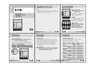
TECHNICAL DATA <strong>ZW</strong> FB <strong>10</strong><br />
<br />
<br />
Batterie: 4 x 1,5 V (AAA)<br />
Frequenz: 868,42 MHz<br />
Betriebstemperatur: 0°C - +40°C<br />
<br />
I Include<br />
E Exclude<br />
<br />
<br />
Low Battery<br />
(status ind. for<br />
battery)<br />
A Associate<br />
• Transmitting frequency: 868.42 MHz<br />
• Battery:<br />
4x 1.5 V (LR03 Micro AAA)<br />
• Number of <strong>channel</strong>s: 7 groups (theoretically the<br />
entire network can be combined into<br />
one group).<br />
3 scenes, All ON/OFF<br />
• Operating temperature: 0°C - +40 °C<br />
• Range:<br />
up to <strong>10</strong>0 m free field<br />
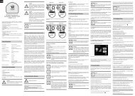
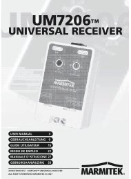
Product details <strong>ZW</strong> FB <strong>10</strong><br />
Å<br />
Up/<br />
on<br />
brighter<br />
LED<br />
(status indication)<br />
S Status<br />
Ç Down/off<br />
darker<br />
Groups<br />
Low Battery<br />
(status ind. for<br />
battery)<br />
A Associate<br />
E Exclude<br />
I Include<br />
On<br />
All On<br />
Scenes<br />
All On/Off<br />
Off<br />
All Off<br />
Using the <strong>remote</strong> <strong>control</strong>, several receivers / appliances can be<br />
allocated to a choice of 7 different groups, 3 scenes that can be<br />
configured as required, or to a central All On/Off group. Special<br />
configuration buttons for programming are under the battery<br />
cover on the rear of the device.<br />
Harkortstr. 2 • 58339 Breckerfeld • Germany • www.duewi.de<br />
II
<strong>Wireless</strong> <strong>remote</strong> <strong>control</strong><br />
<strong>10</strong>-<strong>channel</strong> <strong>ZW</strong> <strong>fb</strong><br />
GB<br />
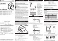
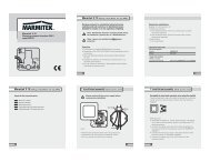
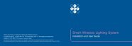
Function buttons on the düwi <strong>control</strong>ler<br />
düwi <strong>remote</strong> <strong>control</strong><br />
art. no. 05445 0<br />
düwi wireless wall transmitter<br />
art. no. 05443 6<br />
düwi wireless switching-centre<br />
art. no. 05447 4<br />
s Status<br />
Å up<br />
Å<br />
up<br />
Ç<br />
down<br />
Include<br />
e Exclude<br />
a Associate<br />
Include<br />
e Exclude<br />
on<br />
All On<br />
off<br />
All Off<br />
a Associate<br />
e Exclude<br />
Include<br />
Ç down<br />
a Associate<br />
Function buttons on the düwi receiver<br />
düwi wireless flush mounted switch, art. no. 05431 3<br />
düwi wireless flush mounted dimmer 300 W, art. no. 05433 7<br />
düwi wireless flush mounted shutter switch, art. no. 05436 8<br />
düwi wireless plug adaptor<br />
switch, art. no. 05437 5<br />
düwi wireless plug adaptor<br />
düwi “Starline”<br />
socket outlet<br />
art. no. 12549 5<br />
1<br />
up/on<br />
2<br />
down/off<br />
dimmer, art. no. 05439 9 1<br />
1<br />
1<br />
1<br />
1<br />
on/off slot 1<br />
on/off slot 2<br />
on/off slot 3<br />
on/off slot 4<br />
on/off slot 5<br />
1<br />
up/on<br />
down/off<br />
slot 1<br />
LED indications<br />
Due to the colour LED indication on transmitters and receivers it is possible at any time to obtain feedback on the success/<br />
failure of a switching command or a configuration step, to specifically enquire about the status of devices, or to monitor the<br />
switching status or the functionality of devices.<br />
ellow<br />
Blue<br />
Red<br />
ellow flashing<br />
Blue flashing<br />
Green<br />
Green flashing<br />
Red flashing<br />
Red/Green<br />
Red/ellow/Green<br />
Combinations are possible within a group.<br />
Device/group/scene is switched on<br />
Device/group/scene is switched off<br />
Device/group/scene erroneous/configuration not successful/out of range<br />
Dimmer increasing brightness<br />
Dimmer reducing brightness<br />
Configuration successful<br />
Configuration active<br />
Low battery in the network/child protection active/temperature too high<br />
Device not programmed<br />
Device not programmed<br />
slot 2<br />
.<br />
Harkortstr. 2 • 58339 Breckerfeld • Germany • www.duewi.de<br />
III
<strong>Wireless</strong> <strong>remote</strong> <strong>control</strong><br />
<strong>10</strong>-<strong>channel</strong> <strong>ZW</strong> <strong>fb</strong><br />
GB<br />
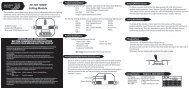
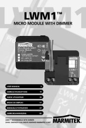
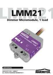
TECHNICAL drawings<br />
70.9<br />
1.5<br />
<strong>10</strong>.6<br />
3<br />
6<br />
R2<br />
4<br />
+0.2<br />
80 -0.2<br />
45<br />
70.9<br />
60 -0.1<br />
+0.1<br />
12.9<br />
Harkortstr. 2 • 58339 Breckerfeld • Germany • www.duewi.de<br />
IV
GB<br />
Contents<br />
1.0 The Z-Wave ® wireless system6<br />
1.1 Information on the Z-Wave wireless system 6<br />
1.2 Advantages of the Z-Wave wireless system 6<br />
2.0 General notes6<br />
2.1 Correct use 6<br />
2.2 General safety instructions 7<br />
3.0 User manual7<br />
3.1 LED indications 8<br />
3.1.1 Overview of LED indications on the devices8<br />
3.1.2 Advantages of the LED indications 8<br />
3.1.3 Delivery state8<br />
3.2 Setting up a simple wireless network (without switching centre/server)8<br />
3.2.1 Including devices in a group/scene 8<br />
3.2.2 Deleting/removing included devices 9<br />
3.2.3 Checking the switching status (status enquiry) 9<br />
3.3 Resetting system components/the system 9<br />
3.3.1 Removing a device from the network 9<br />
3.3.1 Removing an additional <strong>control</strong>ler from the network<strong>10</strong><br />
3.3.3 Deleting primary <strong>control</strong>ler and network<strong>10</strong><br />
3.3.4 Deleting wireless switching centre/server as primary <strong>control</strong>ler and network 11<br />
3.4 Expanded functions 11<br />
3.4.1 Including devices in a scene 11<br />
3.4.2 Activation of the All On/All Off functionality12<br />
3.4.3 Child protection function12<br />
3.5 Working with more than one <strong>control</strong>ler13<br />
3.5.1 Including additional <strong>control</strong>lers13<br />
3.5.2 Synchronising additional <strong>control</strong>lers13<br />
3.5.3 Including devices on additional <strong>control</strong>lers13<br />
3.5.4 Allocating an included device to a group/scene14<br />
3.5.5 Connecting flush-mount modules14<br />
3.5.6 Connecting flush mounted modules or plug adaptors to a wall transmitter <br />
(without direct wireless connection)15<br />
3.6 Managing groups/scenes on the <strong>control</strong>lers15<br />
3.6.1 Removing devices from a group/scene – devices remain in the network15<br />
3.6.2 Deleting a complete group/scene – devices remain in the network16<br />
3.6.3 Removing a faulty or temporarily inactive device from a group/scene16<br />
3.7 Setting up a wireless network with a wireless switching centre/server16<br />
3.7.1 Integration of a wireless switching centre/server in an existing network17<br />
3.7.2 Setting up a new network using a wireless switching centre/server17<br />
4.0 Annex18<br />
4.1 Warranty18<br />
4.2 Disposal18<br />
4.3 Glossary18<br />
Page
GB<br />
1.0 The Z-Wave ® radio system<br />
1.1 Information on the Z-Wave radio system<br />
Z-Wave ®<br />
• Is an internationally established and defined standard for the <strong>control</strong> of wireless systems<br />
• Is a professional, reliable and easy to operate wireless system on the interference-free frequency of 868.42 MHz<br />
• Is future-proof and can be expanded step-by-step to form a complex system using the mutually compatible products<br />
from the Z-Wave Alliance<br />
Products with this logo guarantee the best possible compatibility and ensure that Z-Wave products<br />
from other, well-known manufacturers are supported and can be integrated into existing systems.<br />
Z-Wave ® is a registered trademark of Zensys Inc. and its subsidiaries in the USA and other<br />
countries.<br />
1.2 Advantages of the Z-Wave wireless system<br />
With the Z-Wave wireless system from düwi, which is based on international standards, you can conveniently and easily<br />
switch on and off your heating and air-conditioning system, electrical appliances or your entertainment electronics.<br />
Z-Wave offers numerous advantages over conventional wireless systems: Due to a bidirectional wireless connection<br />
(command and reply are displayed) and the usage of multi-colour LEDs it is possible to enquire about the status of<br />
specific devices at any time (on/off/up/down/battery charge state) or to obtain feedback of the success/failure of<br />
switching commands or configuration steps.<br />
Z-Wave uses interacting network nodes. The<br />
individual receivers/appliances are connected<br />
together and therefore form a tightly meshed<br />
wireless network in which the signals are forwarded<br />
to the next, neighbouring receiver. Due to this<br />
forwarding function, individual devices act like<br />
amplifiers. It is therefore also possible to reach<br />
devices that are not within the immediate wireless<br />
range of the <strong>remote</strong> <strong>control</strong> (mesh-type network<br />
structure). As a result the system can also manage<br />
several, alternative connections between individual<br />
devices, the availability in the wireless network is<br />
thus significantly increased and the susceptibility to<br />
interference reduced.<br />
<br />
2.0 General notes<br />
2.1 Correct use<br />
All Z-Wave devices are only suitable for usage in dry rooms indoors. The wireless plug adaptor switch IP44 (art. no.<br />
05438 2 ) is also suitable for use outdoors.<br />
All Z-Wave devices comply with the applicable European CE directives.
GB<br />
2.2 General safety instructions<br />
Only authorised, suitably qualified personnel are allowed to work on 230 V mains taking into account<br />
national installation regulations/standards. Prior to installing the product, the mains supply is to be isolated<br />
and secured against unintentional switch on.<br />
In the case of battery-operated devices, attention is to be paid to the correct polarity of the batteries on<br />
insertion.<br />
• The product is only allowed to be used as intended (as described in the user manual). Any claims under the warranty<br />
will be rendered void if changes or modifications have been made, or the devices have been painted. The product<br />
must be immediately checked for damage on unpacking. In the event of damage, the product must not be placed in<br />
operation under any circumstances. If hazard-free operation of the product cannot be ensured, it must be unplugged or<br />
disconnected without delay and secured against unintentional operation.<br />
• Do not switch any appliances that could cause injury/damage if switched on unintentionally (e.g. circular saws, lifesupport<br />
systems).<br />
• Only switch appliances that are approved for operation at 230V/50Hz.<br />
• Do not use wireless dimmers/switches for safety purposes (e.g. as an emergency stop or for making an emergency<br />
call).<br />
• Only load wireless dimmers/switches to the stated maximum power.<br />
The device is a wireless article with Z-Wave technology. If parts of this device do not work correctly, your<br />
safety will not be at risk, there will simply be a loss of function. In this case the devices can be switched<br />
manually by pressing the button.<br />
3.0 User manual<br />
düwi wireless <strong>remote</strong><br />
<strong>control</strong> <br />
art. no. 05445 0<br />
düwi wireless wall<br />
transmitter<br />
art. no. 05443 6<br />
düwi wireless switching<br />
centre/server<br />
art. no. 05447 4<br />
Every <strong>control</strong>ler (e.g. <strong>remote</strong> <strong>control</strong>, wall transmitter or wireless switching centre/server) comes from the<br />
factory with a unique identification number (ID). When additional devices are included, this ID is provided to<br />
the other devices resulting in a coded, self-contained wireless network. This feature is advantageous if several<br />
households in the immediate vicinity use the same system, e.g. on housing estates, in semi-detached houses or<br />
terraced housing schemes.
GB<br />
3.1 LED Indications<br />
3.1.1 Overview of LED indications on the devices<br />
You will find an overview of the various LED indications on page 2.<br />
3.1.2 Advantages of the LED indications<br />
As a result of the colour LED indication on the transmitters and receivers it is at all times possible<br />
• To obtain feedback on the success/failure of switching commands or configuration steps.<br />
• To enquire about the status of devices (on/off/up/down/battery).<br />
• To monitor the switching status and the functionality of devices that are outside the field of view or on other floors.<br />
3.1.3 Delivery state<br />
During commissioning or the first time a button is pressed, the delivery state (not programmed) of the devices is indicated<br />
by a red/green flashing LED.<br />
3.2 Setting up a simple wireless network (without wireless switching centre/server)<br />
This section describes the commissioning of a simple network with the basic functions on the initial usage of only one<br />
<strong>control</strong>ler (<strong>remote</strong> <strong>control</strong> or wall transmitter). For more extensive features, please see from section 3.4.<br />
Please note that the <strong>control</strong>ler (<strong>remote</strong> <strong>control</strong>, wall transmitter) that you activate first is the primary <strong>control</strong>ler<br />
that allocates a unique, interference-free address or identification number (ID) to the entire wireless network.<br />
You can only add further devices to the network using this primary <strong>control</strong>ler. In the case of loss or damage to<br />
the primary <strong>control</strong>ler, the complete wireless network must be re-configured. We recommend the usage of a<br />
<strong>remote</strong> <strong>control</strong> or a wireless switching centre/server as the primary <strong>control</strong>ler.<br />
On the installation of more complex systems, e.g. on the usage of several <strong>control</strong>lers (<strong>remote</strong> <strong>control</strong>s/wall transmitters)<br />
we generally advise the usage of a wireless switching centre/server (art. no. 05447 4 ). It simplifies operation during<br />
configuration, secures and co-ordinates the data in the wireless network, monitors the battery state of the devices and as<br />
a result reduces the battery usage of other <strong>control</strong>lers (<strong>remote</strong> <strong>control</strong>s/wall transmitters).<br />
3.2.1 (Directly) including devices in a group/scene<br />
Controller LED Receiver LED<br />
3x Å / Ç<br />
flashes<br />
green<br />
3x 1 / 2<br />
leuchtet illuminates<br />
grün green<br />
• Press 3x within 1.5 seconds the "UP" Å or "DOWN" Ç button for the group on the <strong>remote</strong> <strong>control</strong> in which the device<br />
is to be included.<br />
• The LED starts to flash green and permits the inclusion of devices for 15 seconds.<br />
• In the case of a plug adaptor press 3x within 1.5 seconds the function button ( 1 ); during this process the device<br />
retains its last switching status ("on" or "off").<br />
• In the case of a flush mounted module press 3x within 1.5 seconds either the "UP" 1 or "DOWN" 2 button.<br />
During this process you can choose whether the device and any connected neighbouring devices switch on (by<br />
pressing the "UP" 1 button) or switch off (by pressing the "DOWN" 2 button).
GB<br />
Both <strong>control</strong>ler and target device indicate successful inclusion for 3 seconds with a green LED indication, failed inclusion<br />
with a red LED indication. The device is now allocated directly to the required group. Repeat the procedure to include<br />
additional devices.<br />
In general you can allocate a device to one or more different groups (e.g. a standard lamp can be switched in group "1"<br />
with the dining room lighting and in group "2" with the living room lighting).<br />
3.2.2 Deleting/removing included devices<br />
You can undo the inclusion of devices by:<br />
• Removing the devices from a group/scene (the device remains in the network, disassociation see 3.6.1).<br />
• Removing a device from the network (Reset device or Exclude device from the network, see 3.3.1).<br />
• Deleting a complete group/scene (devices remain in the network, disassociation, see 3.6.2).<br />
• Completely resetting the system (see 3.3.1–3.3.4).<br />
3.2.3 Checking the switching status (status enquiry)<br />
Controller<br />
1x S<br />
LED<br />
zeigt indicates Status<br />
an status (siehe (see<br />
Umschlag page 2)<br />
Seite I)<br />
• By pressing the related middle button S on the <strong>remote</strong> <strong>control</strong> you can display the switching status of a group on the<br />
LED indicator on the <strong>remote</strong> <strong>control</strong> (LED indications on the cover, page I).<br />
• To enquire about the switching status of the entire network, press the middle button in the "All On/Off" group for 2<br />
seconds until the LED flashes green briefly.<br />
• Then an enquiry about the switching status of all devices in the network is sent and the status indicated.<br />
3.3 Resetting system components/the system<br />
Resetting all system components to the delivery state or a complete network reset is to be undertaken as follows; the<br />
scope of the reset increases step-by-step in the following sections.<br />
3.3.1 Removing a device from the network (Reset or Exclude device from the network)<br />
Controller LED Receiver LED<br />
2 sec. .<br />
E<br />
blinkt flashes<br />
grün green<br />
3x 1 / 2<br />
leuchtet illuminates<br />
grün<br />
• To remove a device you can use any <strong>control</strong>ler (<strong>remote</strong> <strong>control</strong>, wall transmitter or wireless switching centre/server)<br />
• Press for 2 seconds the "Exclude" E button on the <strong>control</strong>ler.<br />
• The LED starts to flash green and permits the removal of devices for 15 seconds.<br />
• In the case of a plug adaptor press 3x within 1.5 seconds the function button ( 1 ), during this process the device<br />
retains its last switching status ("on" or "off").<br />
• In the case of a flush mounted module press 3x within 1.5 seconds either the "UP" 1 or the <br />
"DOWN" 2 button. During this process you can choose whether the device and any connected neighbouring devices<br />
switch on (by pressing the "UP" 1 button) or switch off (by pressing the "DOWN" 2 button).
GB<br />
Both <strong>control</strong>ler and target device indicate successful removal for 3 seconds with a green LED indication, failed removal<br />
with a red LED indication.<br />
After successful removal, the device is in the delivery state again.<br />
3.3.2 Removing an additional <strong>control</strong>ler from the network<br />
(e.g. resetting <strong>remote</strong> <strong>control</strong> or wall transmitter)<br />
If you do not want to reset the complete network, but just one <strong>control</strong>ler (<strong>remote</strong> <strong>control</strong> or wall transmitter), proceed as<br />
follows:<br />
Controller 1 LED Controller 2 LED<br />
2 sec<br />
2 sec<br />
E<br />
I<br />
blinkt flashes<br />
leuchtet illuminates<br />
grün green<br />
grün green<br />
• Press the "Exclude" E button on your primary <strong>control</strong>ler for 2 seconds (any <strong>control</strong>ler in network with wireless switching<br />
centre/server).<br />
• The LED starts to flash green and permits the removal of the <strong>control</strong>ler for 15 seconds.<br />
• Press for 2 seconds the "Include" I button on the <strong>control</strong>ler you want to remove.<br />
Both <strong>control</strong>lers indicate successful resetting for 3 seconds with a green LED indication, failed resetting with a red LED<br />
indication.<br />
After successful resetting, the device is in the delivery state again.<br />
3.3.3 Deleting primary <strong>control</strong>ler and network<br />
If you have a network without a wireless switching centre/server, the complete network can be deleted with the following<br />
steps. For a system with a wireless switching centre/server, for resetting see 3.3.4.<br />
Controller LED Controller LED Controller LED<br />
5 sec<br />
E<br />
blinkt flashes<br />
grün green …<br />
3x / On Å<br />
… blinkt flashes<br />
rot/gelb/ red/yellow/<br />
grün green<br />
3x / Ç<br />
illuminates<br />
green<br />
• Press the "Exclude" E button on the <strong>control</strong>ler for 5 seconds.<br />
• The LED starts to flash green and changes to red/yellow/green flashing<br />
• Press 3x within 1.5 seconds the "All On" On button (on a <strong>remote</strong> <strong>control</strong>) or "UP" Å button (on a wall transmitter).<br />
• Press 3x within 1.5 seconds the "All Off" Off button (on a <strong>remote</strong> <strong>control</strong>) or "DOWN" Ç button<br />
(on a wall transmitter).<br />
• The LED starts to flash green quickly.<br />
Successful deletion is indicated for 3 seconds with a green LED indication, failed deletion with a red LED indication.<br />
<strong>10</strong>
GB<br />
3.3.4 Deleting wireless switching centre/server as primary <strong>control</strong>ler and network<br />
If you have a wireless switching centre/server as the primary <strong>control</strong>ler in the network, the network data are deleted as<br />
follows:<br />
Controller<br />
<strong>10</strong> sec.<br />
I + E + A<br />
LED<br />
flashes<br />
red/yellow/<br />
green<br />
• Press simultaneously for <strong>10</strong> seconds the "Include" I + "Exclude" E + " Associate" A buttons on the <strong>control</strong>ler.<br />
A successful reset is indicated by red/yellow/green flashing of the status LED.<br />
3.4 Expanded functions<br />
Along with the basic functions already described, other configurations are possible.<br />
3.4.1 (Directly) including devices in a scene<br />
A scene makes it possible for you to switch devices to a pre-programmed, defined value and thus to realise various light,<br />
switch or mood scenarios (e.g. shutter half way down and lights dimmed to 60 % in the evening for watching television).<br />
Controller LED Receiver LED<br />
3x Å / Ç<br />
flashes<br />
green<br />
3x 1 / 2<br />
leuchtet illuminates<br />
grün green<br />
• Press 3x within 1.5 seconds the "UP" Å or "DOWN" Ç button for the required scene on the <strong>remote</strong> <strong>control</strong> in which the<br />
device is to be included.<br />
• The LED starts to flash green and permits the inclusion of devices for 15 seconds.<br />
• Place the device in the required switching status or to the required brightness.<br />
• In the case of a plug adaptor press 3x within 1.5 seconds the function button ( 1 ). During this process the device will<br />
retain its last switching status and brightness setting.<br />
• In the case of a flush mounted module press 3x within 1.5 seconds either the "UP" 1 or "DOWN" 2 function<br />
button.<br />
During this process you can choose whether the device then switches on (by pressing the "UP" 1 button) or switches off<br />
(by pressing the "DOWN" 2 button).<br />
Both <strong>control</strong>ler and target device indicate successful inclusion for 3 seconds with a green LED indication, failed inclusion<br />
with a red LED indication.<br />
The device is now allocated to the required scene and on the activation of the related scene will be placed directly in the<br />
programmed switching status or to the programmed brightness.<br />
11
GB<br />
3.4.2 Activation of the All On/All Off functionality<br />
To be able switch devices from different groups or scenes simultaneously (e.g. switching off all appliances on leaving the<br />
housing or switching on all lights in case of danger), these devices can be specifically allocated to the All On/Off group<br />
on the <strong>remote</strong> <strong>control</strong> or a wall transmitter.<br />
Remote <strong>control</strong><br />
Receiver<br />
2 sec.<br />
On/ / I + A S 3x 1 / 2<br />
• Press simultaneously for 2 seconds the "Include" I and "Associate" A buttons on the rear of the <strong>remote</strong> <strong>control</strong>.<br />
• On the front, in the "All On/Off" group, press one of the following buttons:<br />
– "On" On , to add the device to the All On group<br />
– "Off" Off , to add the device to the All Off group<br />
– "On" On and "Off" Off together to add the device to the All On/Off group <br />
– "Status" S , to remove the device from the All On/Off group.<br />
• In the case of a plug adaptor press 3x within 1.5 seconds the function button ( 1 ), during this process the device<br />
retains its last switch state ("on" or "off").<br />
• In the case of a flush mounted module press 3x within 1.5 seconds either the "UP" 1 or "DOWN" 2 function<br />
button.<br />
During this process you can choose whether the device and any connected neighbouring devices then switch on (by<br />
pressing the "UP" 1 button) or switch off (by pressing the "DOWN" 2 button).<br />
• In the case of a wall transmitter press 3x within 1.5 seconds either the "UP" Å or "DOWN" Ç function button.<br />
During this process you can choose whether the devices and any connected neighbouring devices then switch on (by<br />
pressing the "UP" Å button) or switch off (by pressing the "DOWN" Ç button).<br />
3.4.3 Child protection function<br />
In the case of the child protection function you can select whether it is to be possible to operate a device only after<br />
manual "unlocking" via the buttons (sequence protection) or in general the device can only be operated wirelessly.<br />
Controller LED Controller Receiver<br />
2 sec.<br />
I + A<br />
blinkt flashes<br />
grün green<br />
Å / Ç / S 3x 1 / 2<br />
• Press simultaneously for 2 seconds the "Include" I and "Associate" A buttons on the <strong>control</strong>ler until the LED flashes<br />
green.<br />
• Select the required type of protection as follows. <br />
– Group 1 "UP" Å button to deactivate the child protection<br />
– Group 1 "Status" S button to activate the sequence protection<br />
– Group 1 "DOWN" Ç button to be only able to operate the device wirelessly<br />
• In the case of a plug adaptor press 3x within 1.5 seconds the function button ( 1 ), during this process you can select<br />
whether the device is to be switched on or switched off.<br />
• In the case of a flush mounted module press 3x within 1.5 seconds either the "UP" 1 or "DOWN" 2 function<br />
button.<br />
During this process you can choose whether the device and any connected neighbouring devices then switch on (by<br />
pressing the "UP" 1 button) or switch off (by pressing the "DOWN" 2 button).<br />
12
GB<br />
In the case of the "Sequence" type of protection, the device can be unlocked briefly by pressing 3x the function buttons<br />
( 1 / 2 ), the LED indication illuminates green if successful. 5 seconds after the last button press the device is protected<br />
again automatically, the LED indication flashes red during this process.<br />
3.5 Working with more than one <strong>control</strong>ler<br />
3.5.1 Including additional <strong>control</strong>lers (wall transmitter, <strong>remote</strong> <strong>control</strong>) Include and Replication<br />
During this process an additional <strong>control</strong>ler is included in the network using the primary <strong>control</strong>ler (or in the case of the<br />
usage of a wireless switching centre/server using any <strong>control</strong>ler)<br />
Controller 1 LED Controller 2 LED LED<br />
3x I<br />
blinkt flashes<br />
grün green<br />
2 sec.<br />
I<br />
blinkt flashes<br />
grün green<br />
leuchtet illuminates<br />
grün green<br />
• Press 3x the "Include" I button on your primary <strong>control</strong>ler (any <strong>control</strong>ler in network with wireless switching centre/<br />
server).<br />
• The LED starts to flash green for 15 seconds.<br />
• Press for 2 seconds the "Include" I button on the <strong>control</strong>ler you want to include.<br />
• The LED starts to flash green.<br />
• As soon as the inclusion (and update) of the additional <strong>control</strong>ler starts, the frequency at which the LEDs on both<br />
<strong>control</strong>lers flash increases.<br />
Successful inclusion of the additional <strong>control</strong>ler is indicated for 3 seconds with a green LED indication on both devices,<br />
failed inclusion with a red LED indication.<br />
3.5.2 Synchronising additional <strong>control</strong>lers (in the case of network without wireless switching<br />
centre/server)<br />
As initially only the primary <strong>control</strong>ler has the current network data, it is sensible to synchronise all <strong>control</strong>lers to ensure<br />
the stable function of the network. To synchronise, repeat the the inclusion process from point 3.5.1 for each <strong>control</strong>ler<br />
you want to update.<br />
3.5.3 Including devices on additional <strong>control</strong>lers<br />
Here a device is registered in the network using the primary <strong>control</strong>ler (or on the usage of a wireless switching centre/<br />
server using any <strong>control</strong>ler), without direct allocation to a group. The device can then also be allocated to the group/<br />
scene on other <strong>control</strong>lers in the network, e.g. an additional wall transmitter or if the device is not to be switched via the<br />
primary <strong>control</strong>ler.<br />
Controller LED Receiver LED<br />
3x I<br />
blinkt flashes<br />
grün green<br />
3x 1 / 2<br />
illuminates<br />
green<br />
• Press 3x the "Include" I button on your primary <strong>control</strong>ler (any <strong>control</strong>ler in network with wireless switching centre/<br />
server).<br />
• The LED starts to flash green and permits the inclusion of devices for 15 seconds.<br />
• In the case of a plug adaptor press 3x within 1.5 seconds the function button ( 1 ), during this process the device<br />
retains its last switching status.<br />
• In the case of a flush mounted module press 3x within 1.5 seconds either the "UP" 1 or the <br />
"DOWN" 2 button. During this process you can choose whether the device and any connected neighbouring devices<br />
then switch on (by pressing the "UP" 1 button) or switch off (by pressing the "DOWN" 2 button).<br />
13
GB<br />
Both <strong>control</strong>ler and target device indicate successful inclusion for 3 seconds with a green LED indication, failed inclusion<br />
with a red LED indication.<br />
3.5.4 Allocating an already included device to any group/scene<br />
(If the device is to be allocated to a scene with a defined nominal state, e.g. with a specific brightness, set to device to<br />
this state by pressing the related function button ( 1 / 2 ).)<br />
Controller LED Receiver LED<br />
3x Å / Ç<br />
blinkt flashes<br />
grün green<br />
3x 1 / 2<br />
leuchtet illuminates<br />
grün<br />
• Press 3x within 1.5 seconds on the required <strong>control</strong>ler the "UP" Å or "DOWN" Ç button for the required group/scene.<br />
• The LED starts to flash green and permits the allocation of devices for a period of 15 seconds.<br />
• Press 3x within 1.5 seconds a function button ( 1 / 2 )<br />
on the receiving device (e.g. plug adaptor, flush mounted module).<br />
Both <strong>control</strong>ler and receiving device indicate successful allocation for 3 seconds with a green LED indication, failed<br />
allocation with a red LED indication.<br />
The device is now allocated directly to the related group.<br />
3.5.5 Connecting flush-mount modules<br />
The flush mounted modules make it possible to connect up to four devices, e.g. to simultaneously switch or dim several<br />
devices simultaneously.<br />
Controller Receiver Controller LED<br />
2 sec.<br />
A<br />
1x I 3x 1 / 2<br />
3x Å / Ç<br />
leuchtet illuminates<br />
grün green<br />
• Press for 2 seconds the "Associate" A button on the <strong>control</strong>ler of your choice.<br />
• Briefly press the "Include" I button on the same <strong>control</strong>ler.<br />
• Press 3x within 1.5 seconds either the "UP" 1 or "DOWN" 2 button on the receiving device (this device is <strong>control</strong>led<br />
by the connected device).<br />
• Press 3x within 1.5 seconds either the "UP" Å or "DOWN" Ç button on the <strong>control</strong>ler (this device <strong>control</strong>s the<br />
connected device).<br />
The <strong>control</strong>ler indicates successful connection for 3 seconds with a green LED indication, failed connection with a red LED<br />
indication.<br />
To be able also to switch the devices both ways, repeat the above procedure with the order reversed.<br />
14
GB<br />
3.5.6 Connecting flush mounted modules or plug adaptors with a wall transmitter<br />
(if there is no direct wireless connection)<br />
If you want to connect a wall transmitter with a flush mounted module in the network that cannot be reached directly from<br />
a wall transmitter already installed, proceed as follows<br />
Controller Receiver Controller 2<br />
2 sec.<br />
A<br />
1x I 3x 1 / 2<br />
3x Å / Ç<br />
• Press for 2 seconds the "Associate" A button on the <strong>control</strong>ler.<br />
• Briefly press the "Include" I button on the <strong>control</strong>ler.<br />
• Press 3x within 1.5 seconds either the "UP" 1 or "DOWN" 2 button on the receiving device.<br />
• Press 3x within 3 seconds the function button ( Å / Ç ) on the receiving device.<br />
Please note that to operate the device at least one device that supports routing (plug adaptor, flush mounted module,<br />
wireless switching centre/server) is required to establish a connection between the wall transmitter and the device.<br />
3.6 Managing groups/scenes on the <strong>control</strong>lers<br />
It is possible at any time to change the membership (allocation) of device in groups/scenes, e.g. to add or remove<br />
individual devices from a group/scene or to reset entire groups/scenes.<br />
3.6.1 Removing devices from a group/scene – devices remain in the network (Disassociation)<br />
Controller LED Controller LED Receiver LED<br />
2 sec.<br />
A<br />
blinkt flashes<br />
grün green<br />
(schnell) (quickly)<br />
1x Ç<br />
blinkt flashes<br />
grün green<br />
(langs.) (slowly)<br />
3x 1 / 2<br />
illuminates<br />
green<br />
• Press the "Associate" A button on the related <strong>control</strong>ler for 2 seconds<br />
(<strong>remote</strong> <strong>control</strong>/wall transmitter).<br />
• The LED starts to flash green (quickly).<br />
• Press the "DOWN" Ç button on the <strong>control</strong>ler for the related group/scene.<br />
• The LED starts to flash green (slowly)<br />
• In the case of a plug adaptor press 3x within 1.5 seconds the function button ( 1 ).<br />
• In the case of a flush mounted module press 3x within 1.5 seconds either the "UP" 1 or "DOWN" 2 function<br />
button.<br />
The receiving device indicates successful removal for 3 seconds with a green LED indication, failed removal with a red<br />
LED indication.<br />
The device has been removed from the group/scene and will no longer be operated or displayed.<br />
15
GB<br />
3.6.2 Deleting a complete group/scene – devices remain in the network (Disassociation)<br />
Controller LED Controller LED<br />
<strong>10</strong> sec.<br />
A<br />
flashes blinkt<br />
red/yellow/ rot/gelb/<br />
green grün<br />
1x Ç<br />
leuchtet illuminates<br />
grün green<br />
• Press the "Associate" A button on the related <strong>control</strong>ler for <strong>10</strong> seconds<br />
(<strong>remote</strong> <strong>control</strong>/wall transmitter).<br />
• The LED starts to flash red/yellow/green.<br />
• Press the "DOWN" Ç button on the <strong>control</strong>ler for the related group/scene.<br />
The <strong>control</strong>ler signals successful deletion of a group/scene for 3 seconds with a green LED indication, failed deletion with<br />
a red LED indication.<br />
The group/scene is now blank and can be configured again.<br />
3.6.3 Removing a faulty or temporarily inactive device from a group/scene<br />
If a device in a group/scene is faulty or is to be temporarily set inactive (e.g. if a plug adaptor has been removed) and<br />
can therefore no longer be reached, after an attempt at switching or enquiring about the status the message "Device<br />
faulty" is returned. This error message can be suppressed by automatic deactivation of the device. If this device is reactivated<br />
(e.g. if a plug adaptor is plugged in again), it is automatically reallocated to the original group/scene.<br />
Controller<br />
<strong>10</strong> sec.<br />
S<br />
LED<br />
leuchtet illuminates<br />
grün green<br />
• Press for <strong>10</strong> seconds the "Status" S button for the related group/scene on the <strong>control</strong>ler, if you want to clear the status<br />
indication for a group.<br />
• Press for <strong>10</strong> seconds the "Status" S button for the "All On/Off" group on the <strong>control</strong>ler, if you want to clear the<br />
complete network (e.g. in the case of the loss or destruction of a device)<br />
The <strong>control</strong>ler indicates successfull clearing of the status indication for a group or the network for 3 seconds with a green<br />
LED indication, failed clearing with a red LED indication.<br />
3.7 Setting up a wireless network with wireless switching centre/server<br />
On the installation of more complex systems, e.g. on the usage of several <strong>control</strong>lers (<strong>remote</strong> <strong>control</strong>s/wall transmitters)<br />
we generally advise the usage of a wireless switching centre/server (art. no. 05447 4 ). It simplifies operation during<br />
configuration, secures and co-ordinates the data in the wireless network, monitors the battery state of the devices and as<br />
a result reduces the battery usage of other <strong>control</strong>lers (<strong>remote</strong> <strong>control</strong>s/wall transmitters).<br />
In general it is possible at any time to expand an existing network with a wireless switching centre/server.<br />
In a network with a wireless switching centre/server, it is possible to include devices in the network or remove devices<br />
from the network using any <strong>control</strong>ler.<br />
16
GB<br />
3.7.1 Inclusion of a wireless switching centre/server in an existing network<br />
First include the wireless switching centre/server in the current primary <strong>control</strong>ler:<br />
Controller LED Switching<br />
server LED<br />
2 sec.<br />
3x I<br />
blinkt flashes<br />
grün green<br />
I<br />
illuminates<br />
green<br />
• Press 3x the "Include" I button on the primary <strong>control</strong>ler.<br />
• The LED starts to flash green and permits the inclusion of the wireless switching centre/server for 15 seconds.<br />
• Press for 2 seconds the "Include" I button on the wireless switching centre/server.<br />
<strong>Wireless</strong> switching centre/server and <strong>control</strong>ler indicate successful inclusion for 3 seconds with a green LED indication,<br />
failed inclusion with a red LED indication.<br />
Next include in succession all other <strong>control</strong>lers (<strong>remote</strong> <strong>control</strong>, wall transmitter) and battery-operated devices that were<br />
already in the network and that were not previously known to the wireless switching centre/server.<br />
Switching<br />
server<br />
3x I<br />
LED Controller LED<br />
2 sec.<br />
blinkt flashes<br />
grün<br />
I<br />
leuchtet illuminates<br />
grün<br />
• Press 3x the "Include" I button on the wireless switching centre/server.<br />
• The LED starts to flash green and permits the re-inclusion of the <strong>control</strong>ler for 15 seconds.<br />
• Press for 2 seconds the "Include" I button on the <strong>control</strong>ler.<br />
<strong>Wireless</strong> switching centre/server and <strong>control</strong>ler indicate successful inclusion for 3 seconds with a green LED indication,<br />
failed inclusion with a red LED indication.<br />
3.7.2 Setting up a new network using a wireless switching centre/server<br />
First ensure all devices and <strong>control</strong>lers are in the initial state (red/green flashing LED) – see 3.3.1 (Reset device).<br />
Switching<br />
server<br />
3x I<br />
LED Controller LED<br />
2 sec.<br />
blinkt flashes<br />
grün<br />
I<br />
leuchtet illuminates<br />
grün<br />
• Press 3x the "Include" I button on the wireless switching centre/server.<br />
• The LED starts to flash green and permits the inclusion of the wireless switching centre/server for 15 seconds.<br />
• Press for 2 seconds the "Include" I button on the <strong>control</strong>ler.<br />
<strong>Wireless</strong> switching centre/server and <strong>control</strong>ler indicate successful inclusion for 3 seconds with a green LED indication,<br />
failed inclusion with a red LED indication.<br />
Repeat the process with each additional <strong>control</strong>ler that you want to add to the network. You can now include additional<br />
devices in the network or allocate then to groups and scenes at any time with any included <strong>control</strong>ler.<br />
17
GB<br />
4.0 Annex<br />
4.1 WARRANTY<br />
Claims under the warranty are subject to statutory provisions. Subject to technical change without notice.<br />
• Our products are manufactured using the latest technology and are subject to strict quality <strong>control</strong>. Should,<br />
nevertheless, defects occur on your device, düwi GmbH provides a warranty as detailed below.<br />
• Our warranty covers the improvement or delivery of a new device if the device can be demonstrated to be defective in<br />
relation to its function or the characteristics of the materials used.<br />
• The warranty does neither cover natural wear and tear or transport damage, nor damage as a consequence of failure<br />
to follow the installation instructions or improper installation.<br />
• The warranty is automatically rendered void if the device has been opened after fault diagnostics.<br />
• The duration of the warranty is 24 months from the date of purchase of the device by the end user. Proof of purchase<br />
by means of a bill, delivery note or similar documentation is required to prove that the warranty period has not expired.<br />
• Batteries, lamps and rechargeable batteries supplied are excluded from the warranty.<br />
• düwi GmbH is not liable for indirect or consequential damage, or financial losses.<br />
4.2 Disposal<br />
Within the EU this symbol indicates that this product is not allowed to be disposed of in household waste.<br />
Waste devices contain valuable materials that can be recycled and that should be sent for recycling to prevent<br />
pollution or a health hazard due to the un<strong>control</strong>led disposal of waste.<br />
For this reason please dispose of waste devices via suitable collection systems or send the device to the place<br />
you bought it for disposal. The device will then be sent for recycling.<br />
4.3 Glossary<br />
Include<br />
Exclude<br />
Associate<br />
Disassociate<br />
Reset<br />
Replication<br />
Include devices in a group/scene.<br />
Remove a device from the network<br />
Connect (up to four) devices together so that, e.g., several devices can be switched or dimmed<br />
synchronously and simultaneously<br />
Delete a complete group/scene, devices remain in the network<br />
Reset a device or the system components to the delivery state (not programmed)<br />
Copy the current network data to a further <strong>control</strong>ler (<strong>remote</strong> <strong>control</strong>/wall transmitter/wireless<br />
switching centre/server)<br />
Notes on programming compatible devices from the <br />
Z-Wave Alliance from other manufacturers:<br />
Establish<br />
include mode<br />
Establish<br />
exclude mode<br />
Associate<br />
Reinclude/<br />
Replicate<br />
Disassociate<br />
Learn Mode<br />
Send Node<br />
Info Frame<br />
Add Node<br />
Press 3x the "Include" button on the <strong>control</strong>ler<br />
Press for 2 seconds the "Exclude" button on the <strong>control</strong>ler<br />
For 2 seconds press "Associate" button on the <strong>control</strong>ler, then the "UP" button on the <strong>control</strong>ler<br />
followed by "Send Node Info Frame" on the target device<br />
Press 3x the "Include" button on the <strong>control</strong>ler followed by "Send Node Info Frame" on the target<br />
device<br />
For 2 seconds press "Associate" button the <strong>control</strong>ler, then the "DOWN" button on the <strong>control</strong>ler<br />
followed by "Send Node Info Frame" on the target device<br />
Press 3x "UP" or "DOWN" button<br />
(Slave) Press 3x "UP" or "DOWN" button (<strong>control</strong>ler) for 2 seconds. Press "Include" button<br />
Press 3x "UP" or "DOWN" button (inclusion or primary <strong>control</strong>ler)<br />
18