Chapter 4 Digital Logic and Implementation 4.1 Boolean Algebra
Chapter 4 Digital Logic and Implementation 4.1 Boolean Algebra
Chapter 4 Digital Logic and Implementation 4.1 Boolean Algebra

Create successful ePaper yourself
Turn your PDF publications into a flip-book with our unique Google optimized e-Paper software.
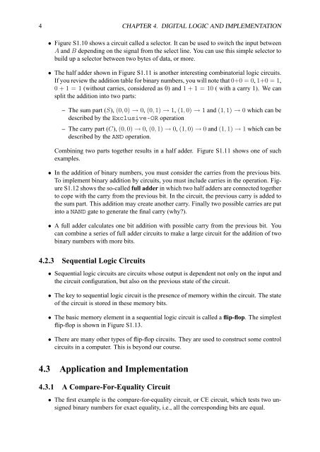
4 CHAPTER 4. DIGITAL LOGIC AND IMPLEMENTATION<br />
• Figure S1.10 shows a circuit called a selector. It can be used to switch the input between<br />
A <strong>and</strong> B depending on the signal from the select line. You can use this simple selector to<br />
build up a selector between two bytes of data, or more.<br />
• The half adder shown in Figure S1.11 is another interesting combinatorial logic circuits.<br />
If you review the addition table for binary numbers, you will note that 0+0 = 0, 1+0 = 1,<br />
0 + 1 = 1 (without carries, considered as 0) <strong>and</strong> 1 + 1 = 10 ( with a carry 1). We can<br />
split the addition into two parts:<br />
– The sum part (S), (0, 0) → 0, (0, 1) → 1, (1, 0) → 1 <strong>and</strong> (1, 1) → 0 which can be<br />
described by the Exclusive-OR operation<br />
– The carry part (C), (0, 0) → 0, (0, 1) → 0, (1, 0) → 0 <strong>and</strong> (1, 1) → 1 which can be<br />
described by the AND operation.<br />
Combining two parts together results in a half adder. Figure S1.11 shows one of such<br />
examples.<br />
• In the addition of binary numbers, you must consider the carries from the previous bits.<br />
To implement binary addition by circuits, you must include carries in the operation. Figure<br />
S1.12 shows the so-called full adder in which two half adders are connected together<br />
to cope with the carry from the previous bit. In the circuit, the previous carry is added to<br />
the sum part. This addition may create another carry. Finally two possible carries are put<br />
into a NAND gate to generate the final carry (why?).<br />
• A full adder calculates one bit addition with possible carry from the previous bit. You<br />
can combine a series of full adder circuits to make a large circuit for the addition of two<br />
binary numbers with more bits.<br />
4.2.3 Sequential <strong>Logic</strong> Circuits<br />
• Sequential logic circuits are circuits whose output is dependent not only on the input <strong>and</strong><br />
the circuit configuration, but also on the previous state of the circuit.<br />
• The key to sequential logic circuit is the presence of memory within the circuit. The state<br />
of the circuit is stored in these memory bits.<br />
• The basic memory element in a sequential logic circuit is called a flip-flop. The simplest<br />
flip-flop is shown in Figure S1.13.<br />
• There are many other types of flip-flop circuits. They are used to construct some control<br />
circuits in a computer. This is beyond our course.<br />
4.3 Application <strong>and</strong> <strong>Implementation</strong><br />
4.3.1 A Compare-For-Equality Circuit<br />
• The first example is the compare-for-equality circuit, or CE circuit, which tests two unsigned<br />
binary numbers for exact equality, i.e., all the corresponding bits are equal.
![Question 1 [22 Marks] In the 1974 Motor Trend US magazine, fuel ...](https://img.yumpu.com/27496340/1/190x245/question-1-22-marks-in-the-1974-motor-trend-us-magazine-fuel-.jpg?quality=85)