D O R MA N V A R I E T X T - Unipart Dorman
D O R MA N V A R I E T X T - Unipart Dorman
D O R MA N V A R I E T X T - Unipart Dorman

Create successful ePaper yourself
Turn your PDF publications into a flip-book with our unique Google optimized e-Paper software.
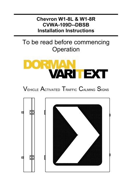
Chevron W1-8L & W1-8R<br />
CVWA-109D--DBSB<br />
Installation Instructions<br />
To be read before commencing<br />
Operation<br />
D O R <strong>MA</strong> N<br />
V A R I T E X T<br />
VEHICLE ACTIVATED TRAFFIC CALMING SIGNS
General.<br />
In general before commencing any installation, all local safety requirements<br />
affecting the safe working environment of the installation either directly or<br />
indirectly should be carried out.<br />
The sign should only be installed both electrically and mechanically, by staff<br />
deemed competent in these fields by their employer.<br />
Any maintenance should be carried out in a clean & dry environment.<br />
View on side and rear of case (W1-8R orientation)<br />
24v dc Input Socket<br />
Data Sockets<br />
2-off Key Locks<br />
Blanking Plug<br />
Medium Signfix<br />
channel.<br />
Clamps supplied for<br />
5.5” dia post and 4”x4”<br />
square post.<br />
4-off Signfix Universal<br />
Clamps UCC 0011<br />
supplied.<br />
In Out<br />
Note: A cable gland is supplied should a hard wired connection be required<br />
(as an alternative to using the 24v dc input socket). Mount the cable gland<br />
on the rear of the case by replacing the blanking plug adjacent to the 24v dc<br />
input socket.<br />
The existing cable from the input socket can be removed from the ‘Power’<br />
terminal block at the bottom left hand side of the VATCS control PCB.<br />
Replace with the alternative power cable taking note of the polarity<br />
markings on the PCB.<br />
2
Mounting arrangements.<br />
The chevron can mounted in a W1-8R or a W1-8L orientation.<br />
In both of these arrangements the supplied drain hole plug must be fitted to<br />
the top of the case as shown in the diagram below.<br />
Schematic block diagram<br />
The Chevrons are linked together using link cable assemblies as specified<br />
on page 4.<br />
Connect ……… Chevron 1 ‘Data Out’ to Chevron 2 ‘Data IN’<br />
Chevron 2 ‘Data Out’ to Chevron 3 ‘Data IN’<br />
Chevron 3 ‘Data Out’ to Chevron 4 ‘Data IN’ etc<br />
3
Cable to Connector Assembly<br />
Supply cable assembly.<br />
To 5A double pole breaker.<br />
Connect +24v dc to socket ‘L’<br />
Connect 0v to socket ‘N’<br />
Supplied 3-way<br />
free socket<br />
connector<br />
2-core supply cable<br />
Link cable assembly.<br />
2-core link cable<br />
Connect pin 1 to pin 1<br />
Connect pin 2 to pin 2<br />
Supplied 4-way<br />
free plug<br />
connectors<br />
Cable Specifications and Cable connectors<br />
• Supply cable: 2 core screened cable suitably rated for the 5 amp<br />
circuit breaker. A 3-way free socket is provided for case connection.<br />
• Link Cable: 2 core screened 1mm 2 . 2-off 4-way free plug<br />
connectors are provided for case connection.<br />
4
Diagnostic information.<br />
Diagnostic information is provided by means of LED indication on the<br />
VATCS Control PCB mounted to the inside of the rear case. The Control<br />
PCB is shown below.<br />
Output / Intensity Status Array<br />
Activity LED<br />
Activity LED<br />
This LED provides indication that the software is running. Under correct<br />
operating conditions the LED will flash continually with a flash rate of 2Hz.<br />
Output Status LED’s (OP1 – OP4)<br />
Under correct operating conditions these four LED’s will be illuminated.<br />
Intensity Status LED’s (OP5 & OP6)<br />
These two LED’s give an indication of the intensity of the Chevron display<br />
LED’s. The display LED’s will vary between a day time (maximum) intensity<br />
and a night time (minimum) intensity with three intermediate stages.<br />
The time to switch from day time to night time intensity (or vice versa) is<br />
approximately one minute.<br />
Table 1 on the following page shows the display intensity status matrix.<br />
5
OP5 LED OP6 LED Intensity of Chevron display LED’s<br />
state state<br />
Off Off Night time setting (minimum intensity)<br />
On Off<br />
Off On Increasing intensity stages.<br />
On On<br />
Flashing Flashing Day time setting (maximum intensity)<br />
Table 1 Display Intensity Status Matrix<br />
Notes:<br />
I. Each intensity step is imperceptible to the human eye.<br />
II. The Chevron will power up at the minimum intensity setting,<br />
ramping up to the maximum intensity in day time in approximately<br />
one minute.<br />
III. When all data links are connected between Chevrons the status<br />
codes will be identical on all units. i.e. All Chevrons will display at<br />
the same intensity level.<br />
IV. All Chevron signs are identical in operation. There is no ‘master’.<br />
6
Specifications.<br />
Supply Voltage:<br />
Nominal Current<br />
Day time conditions<br />
Night time conditions<br />
VATCS control PCB<br />
On board fuse<br />
24v dc<br />
700mA per individual chevron sign<br />
200mA per individual chevron sign<br />
20mm 3.15A Anti Surge<br />
Replacement spare parts.<br />
Case Assembly D26.26053<br />
VATCS Control PCB Assembly D26.26061<br />
PCB and Mask Assembly<br />
Chevron W1-8L & W1-8R D26.26054<br />
Drain Hole Plug B09.09562<br />
Cable Gland B14.14345<br />
3-way Free Socket Connector B13.13726<br />
4-way Free Plug Connector B13.13548<br />
Key EMKA 1004-31<br />
Signfix Universal Channel Clamp B20.20117<br />
7
D O R <strong>MA</strong> N<br />
V A R I T E X T<br />
Wennington Road, Southport. PR9 7TN. England<br />
Tel: +44 (0)1704 518000 Fax: +44 (0)1704 518001<br />
WEB SITE http://www.dorman.co.uk<br />
E <strong>MA</strong>IL address - info@dorman.co.uk<br />
173 Main Street, Bath, Onterio. K0H 1G0. Canada<br />
Tel: 1 613 352 3458 Fax: 613 352 6845<br />
WEB SITE http://www.dormanvaritext.com<br />
E <strong>MA</strong>IL address – enquiry@dormanvaritext.com<br />
Health and safety<br />
Every effort has been made to ensure the accuracy of the information given<br />
in our publications, but in accordance with our policy of continually<br />
improving our products we reserve the right to modify designs and<br />
specifications whenever necessary. All equipment is designed to conform to<br />
relevant British and International standards. Every care is taken to ensure<br />
that, as far as reasonably practical, it will perform without risk to health. It is<br />
essential that accepted codes of professional practice are followed in the<br />
assembly, installation and commissioning of the equipment. If in doubt with<br />
respect to any of these instructions, please consult DOR<strong>MA</strong>N before<br />
installing the device.<br />
<strong>Dorman</strong> reserves the right to vary any component part to meet the required<br />
specifications without prior notice.<br />
8<br />
<strong>Dorman</strong> ref. No C64.64056 Issue x