Download - Radio Frequency Systems
Download - Radio Frequency Systems
Download - Radio Frequency Systems

You also want an ePaper? Increase the reach of your titles
YUMPU automatically turns print PDFs into web optimized ePapers that Google loves.
RADIO FREQUENCY SYSTEMS<br />
The <strong>Radio</strong> <strong>Frequency</strong> <strong>Systems</strong> Bulletin<br />
1st quarter 2006<br />
Digital backhaul<br />
for Chinese DTV<br />
Get a grip—coaxial transmission<br />
line goes Premium<br />
Trouble at the tower top<br />
Ukraine spreads the wireless word<br />
RFS in China, for China<br />
The Clear Choice <br />
Please visit us at www.rfsworld.com<br />
The Clear Choice
The Asianizing of global mobile<br />
2<br />
03 Editorial<br />
The Asianizing of global mobile<br />
04 What’s New<br />
RFS analyzing broadcast<br />
RF remotely<br />
BDAs go dual-band<br />
Three-foot dish gives FCC Cat. A<br />
performance at 11 GHz<br />
MD series duplexers tailor-made<br />
06 Cover Story<br />
Digital backhaul for Chinese DTV<br />
08 Feeder <strong>Systems</strong><br />
Get a grip—coaxial transmission<br />
line goes Premium<br />
12 Wireless Communications<br />
RFS in China, for China<br />
Trouble at the tower top<br />
INDEX<br />
Digital backhaul for Chinese DTV<br />
A digital upgrade to Shandong Broadcast’s<br />
650-kilometer (400-mile) microwave<br />
backhaul network features total<br />
microwave antenna systems from RFS.<br />
The Chinese broadcaster is now one<br />
step closer to DTV.<br />
6<br />
15 Broadcast<br />
Broadband RF now, mobile<br />
TV later<br />
16 Regional Focus<br />
Ukraine spreads the<br />
wireless word<br />
18 In Touch<br />
Barcelona is home to 3GSM 2006<br />
RFS microwave the safe path<br />
in Arizona<br />
Metro Budapest gets wireless<br />
coverage<br />
Growing with Greece<br />
DTF demystified at NATE 2006<br />
Get a grip—coaxial transmission<br />
line goes Premium<br />
Premium attenuation transmission line<br />
solutions are finding favor on mobile<br />
base stations across the globe.<br />
STAY CONNECTED explores this<br />
generational leap in transmission<br />
line technology.<br />
RFS in China, for China<br />
As anticipation builds for the eruption<br />
of third-generation wireless communications<br />
into China, RFS intensifies its<br />
Shanghai RF conditioning and base<br />
station antenna design and<br />
manufacturing activities.<br />
12<br />
8<br />
IMPRINT<br />
<strong>Radio</strong> <strong>Frequency</strong> <strong>Systems</strong><br />
WorldWideWeb:<br />
http://www.rfsworld.com<br />
Publisher: Jörg Springer<br />
Executive Editor/<br />
Editor Asia Pacific South: Peter Walters<br />
Editor EMAI: Regine Suling<br />
Editor Americas North: Ann Polanski<br />
Editor Americas South: Luciana Del Nero<br />
Editor Asia Pacific North: Sammie Qian<br />
Managing Editor: Allan Alderson<br />
Production Editor: Christian Michatsch<br />
Art Director: Matthias Schwedt<br />
Authors: Allan Alderson, Irina Ewert,<br />
Dr. Ellen Gregory, Anita Talberg<br />
Photos: RFS archives, Mick Bennett, Janus Hartvig,<br />
Tony Koopmans, Shelton Muller, Ann Polanski,<br />
Natalia Rivkina, Zhou Xiaoming (Alcatel Shanghai<br />
Bell), Harald Zietz<br />
Cover photography: Zhou Xiaoming<br />
(Alcatel Shanghai Bell)<br />
Cover art: Matthias Schwedt<br />
Print: Print Design, Minden<br />
Layout and Graphics:<br />
inform Advertising, Hannover<br />
Editorial Services:<br />
Relate Technical Communications, Melbourne<br />
Trademarks: CELLFLEX ® , BDA ® , FLEXWELL ® ,<br />
MicroTenna, Optimizer ® , RADIAFLEX ® ,<br />
<strong>Radio</strong> <strong>Frequency</strong> <strong>Systems</strong> ® , RFS ® , RFS CompactLine ® ,<br />
SlimLine ® , RGFLEX ® and The Clear Choice are<br />
trademarks, service marks or registered trademarks<br />
of <strong>Radio</strong> <strong>Frequency</strong> <strong>Systems</strong>.<br />
14<br />
Trouble at the tower top<br />
As the FCC auctions wireless spectrum for<br />
future services in the US, the cocktail of<br />
co-located technologies and frequencies<br />
at the tower top could interact with each<br />
other in unpredictable ways.<br />
16<br />
Ukraine spreads the wireless word<br />
One of the fastest growing wireless markets<br />
in the world, Ukraine leans heavily on RFS<br />
technologies as the foundation for its<br />
nationwide RF networks.<br />
A recent report from the industry research<br />
group, In-Stat, has pointed out a market<br />
trend that many in our sector had long<br />
suspected—that Asia will soon represent the<br />
largest market in the global mobile sector.<br />
The report indicates that the Asian region as<br />
a whole will become the world’s largest<br />
mobile market within the next five to 10<br />
years. It also predicts that the sector’s total<br />
revenue in this region should, by 2009,<br />
improve by more than 40 percent on its<br />
2004 figure. In many respects, this ‘Asian<br />
upswing’ represents a major turning-point<br />
in mobile telecommunications.<br />
The Asian region stretches from the Arabian<br />
Peninsula in the West, to the Pacific island<br />
nations of Japan and Taiwan in the East.<br />
It is largely a ‘new’ entrant to the world of<br />
mobile telecommunications—much of Asia<br />
has only reached significant mobile telecommunications<br />
subscription levels within the<br />
past five years. Two key factors have aided<br />
this recent surge in subscriber count:<br />
extensive deregulation across the region’s<br />
telecommunications sector, and a marked<br />
upturn in regional commerce, notably in the<br />
manufacturing and service provision sectors.<br />
The Asian regional mobile market differs<br />
markedly from its counterparts of Western<br />
Europe and North America in many ways. A<br />
common theme runs through almost all<br />
these differences—the readiness of Asia’s<br />
people to adopt new wireless technologies<br />
and accept fast-paced change, coupled with<br />
the diversity of the wireless markets across<br />
the region. The region also exhibits notably<br />
less penetration of personal computers, and<br />
as a result, less wired Internet access. This<br />
presents as a natural driver toward wireless<br />
connectivity.<br />
In many respects, it is the issue of diversity<br />
that characterizes Asia as a whole. This vast<br />
region is home to around 60 percent of the<br />
world’s population and spans an area over<br />
40 million square kilometers (15 million<br />
square miles). It embraces the most diverse<br />
range of peoples, languages, terrains,<br />
cultures and economies on the planet.<br />
A snapshot of the mobile telecommunications<br />
scenario in three countries of the region<br />
illustrates this amazing diversity—a diversity<br />
that incorporates both ends of the market<br />
spectrum. The Chinese market tripled its<br />
subscriber penetration in the period 2000<br />
to 2004, taking it from ‘insignificant’ status,<br />
to what is today the world’s largest single<br />
mobile market. Japan is by far the world’s<br />
earliest adopter of advanced wireless<br />
technologies, and a market leader in the<br />
roll-out and uptake of 3G telecommunications.<br />
Taiwan represents a similarly amazing<br />
wireless market, boasting the world’s<br />
highest percentage of mobile phone users<br />
(over 100 percent) and a rapid move into<br />
3G mobile services.<br />
By contrast, the region is also home to<br />
countries with notably small gross domestic<br />
product (GDP) figures and some of the<br />
world’s lowest mobile penetration levels.<br />
What is interesting is that most of these small<br />
GDP countries demonstrate extraordinarily<br />
high levels of wireless subscriber growth. The<br />
economic reasoning behind such mobile<br />
Stéphane Klajzyngier<br />
<strong>Radio</strong> <strong>Frequency</strong> <strong>Systems</strong> President<br />
growth has recently been explained in a<br />
report from the London Business School—<br />
a rise of just ten mobile phones per 100 people<br />
can boost GDP growth by 0.6 percentage<br />
points.<br />
Asia, because of its sheer scale and almost<br />
region-wide acceptance and early-adoption<br />
of new wireless technologies, is now clearly<br />
taking control of the technology and<br />
adapting it to suit the region. Over the past<br />
few years, we have seen many small-scale<br />
examples of its potential to drive and mold<br />
the market—Japan’s leading development of<br />
3G telecommunications, the Philippines<br />
national adoption and promotion of the<br />
short message services (SMS), and China’s<br />
unique and innovative Xiaolingtong or ‘Little<br />
Smart’ limited mobility networks. In India’s<br />
case, a recently announced government<br />
objective targets a three- or four-fold increase<br />
in mobile penetration (currently at around<br />
50 million) over the next three years.<br />
Uniquely Indian wireless solutions will<br />
play a major role here.<br />
These are just the tip of the iceberg. As Asia<br />
approaches the registration of the region’s<br />
one billionth subscriber some time in the next<br />
few months, it is clear that the wireless world<br />
will, in many respects, be significantly influenced<br />
by this region’s unique requirements<br />
and broad range of cultures and economies.<br />
This evolutionary stage represents a major<br />
wireless market leap—it will not only change<br />
the face of the global mobile industry,<br />
but provide a major impetus for growth and<br />
evolution.<br />
The challenge from an RF technology<br />
perspective will be to understand and come<br />
to terms with the diversity and the unique<br />
needs of the Asian region. <strong>Radio</strong> <strong>Frequency</strong><br />
<strong>Systems</strong> has long been aware of these, and<br />
the error of many competing wireless<br />
technology groups in trying to apply a ‘onesize-fits-all’<br />
approach, driven from outside<br />
the region. The wireless answer for Asia is<br />
simple: one size does not fit all, and the<br />
EDITORIAL<br />
diversity of the region must be addressed<br />
by solutions that are tailored at a local level.<br />
As a truly global organization, RFS is ideally<br />
positioned to address such a market. For over<br />
a decade, we have made it our business to<br />
grow local participation and knowledge of<br />
the Asian wireless market. It has long been<br />
our view that RF solutions need to be tailored<br />
for any region or country, not enforced from<br />
the outside. Our 11 technical support and<br />
manufacturing centers across Asia, coupled<br />
with our extensive network of in-country<br />
agencies and distributors, ensure extensive<br />
RFS support throughout the region.<br />
In essence, RFS truly knows and understands<br />
Asia, as we have made it is one of our global<br />
‘homes’. We plan to grow our presence in<br />
this exciting and dynamic area and will<br />
continue to support carriers and OEMs in this<br />
important ‘next phase’ of wireless development—the<br />
Asianizing of global mobile.<br />
3
RFS analyzing broadcast<br />
RF remotely<br />
Three-foot dish gives FCC Cat. A<br />
performance at 11 GHz<br />
4 WHAT’S NEW<br />
With the advent of digital television (DTV),<br />
and a global trend towards remote monitoring<br />
of broadcast sites, <strong>Radio</strong> <strong>Frequency</strong><br />
<strong>Systems</strong> has developed a new RF system<br />
monitor. The new system demonstrates<br />
superior accuracy and functionality than any<br />
other on the market, and<br />
can provide remote<br />
access. Incorporating 50<br />
configurable inputs, it<br />
can handle up to 16<br />
transmitters, and an<br />
antenna system with four<br />
main feeders.<br />
The new RF system<br />
monitor is used primarily<br />
for monitoring forward/reflected transmitter<br />
power and for mimic display<br />
of U-Link/motorized switch configurations.<br />
Beyond this, it has the ability to analyze<br />
and store a wide range of collected data<br />
for up to three years. According to<br />
Graham Broad, RFS Product Development<br />
Manager, unmanned broadcast sites<br />
really benefit from the data logging feature.<br />
“The operator needs some immediate analysis<br />
to see what is actually going on inside the<br />
transmitting system—we can do that with<br />
the new RF system monitor,” said Broad.<br />
Founded on microprocessor technology, the<br />
new RF system monitor has superior accuracy<br />
for measuring either peak or true root<br />
mean square (RMS) power of complex<br />
waveforms. It has the ability to compensate<br />
for the effects of temperature variations,<br />
and independently evaluate non-linear<br />
multi-channel systems.<br />
The operator interface has also been<br />
optimized, through the implementation of<br />
an active mimic display on a tablet PC.<br />
Normally integrated into the U-Link frame,<br />
this display allows easy network configuration<br />
and connection to the operator’s local<br />
network. More functionality can be achieved<br />
through enabling Internet connectivity, plus<br />
a Windows-based display allows the user<br />
interface to be customized to suit.<br />
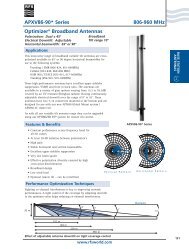
A breakthrough in microwave antenna<br />
design by <strong>Radio</strong> <strong>Frequency</strong> <strong>Systems</strong><br />
provides an exciting new solution for pointto-point<br />
communications in the US 11-GHz<br />
band. The RFS SlimLine SU3-107FC<br />
microwave antenna is the first antenna on<br />
the market—smaller than four feet in<br />
size—to meet the stringent US Federal<br />
Communications Commission (FCC) part<br />
101 Category A requirements in this band.<br />
RFS Area Product Manager, Asad Zoberi,<br />
said that the feed system of the three-foot<br />
SU3-107FC has been re-designed. “Until<br />
now, the only way to meet the FCC<br />
Category A requirements in the 11-GHz<br />
band was to use a four-foot antenna,” he<br />
said. “But this is often an overkill from<br />
the required system gain perspective.<br />
Furthermore, end users are constantly<br />
challenged by zoning and permit<br />
applications—they want antenna solutions<br />
that are smaller and more lightweight to<br />
minimize the tower loading.”<br />
According to Zoberi, the US 11-GHz band<br />
(10.7 to 11.7 GHz) is an ideal option for<br />
point-to-point communications, with links<br />
typically spanning eight to 32 kilometers<br />
(five to 20 miles). It has capacity and<br />
rain-attenuation advantages over the<br />
10-GHz and 18-GHz bands respectively;<br />
however the band has been underutilized<br />
due to lack of smaller antennas that meet<br />
the stringent FCC regulations.<br />
The SU3-107FC is a new addition to<br />
the RFS SlimLine family of ultra highperformance<br />
microwave antennas, and<br />
exhibits all the features and benefits of the<br />
range. This includes a robust mechanical<br />
design and lightweight construction from<br />
corrosion-resistant materials. As the only<br />
antenna smaller than four feet to meet<br />
FCC part 101 Category A requirements in<br />
the 11-GHz band, it will facilitate<br />
zoning and site permit acquisition,<br />
making it the ideal solution for backhaul<br />
applications.<br />
5<br />
BDAs go dual-band<br />
In support of wireless coverage inside<br />
buildings such as car parks and shopping<br />
centers, <strong>Radio</strong> <strong>Frequency</strong> <strong>Systems</strong> has<br />
through a common amplifier for either the<br />
downlink or uplink. The amplifiers are<br />
broadband to cover both the 800- or 900-<br />
developed one of the world’s first MHz bands,” said Ganesh Krishnan, RFS<br />
dual-band bi-directional amplifiers (BDA).<br />
The BDA amplifies the signal from a donor<br />
base antenna, which is then re-distributed<br />
Area Product Manager RF Conditioning.<br />
Providing a high gain of 65-dB to the<br />
signal at the base port, the 48960 BDA<br />
via an indoor ‘service’ antenna system,<br />
providing coverage without the need for<br />
additional radios.<br />
The new 48960 BDA supports US 800-MHz<br />
and 900-MHz specialized mobile radio<br />
(SMR) services in a single compact and<br />
lightweight unit. This saves over<br />
20 percent of the cost of two single-band<br />
units. “The BDA has two<br />
RF ports, one for connecting to<br />
the donor antenna and another<br />
to the service antenna. Inside the<br />
unit, the signals are separately filtered for<br />
out-of-band frequencies, but passed<br />
amplifies the weak signal to improve<br />
coverage in the service area. The BDA also<br />
has a high dynamic range of around 50 dB.<br />
This feature allows the unit to withstand<br />
stronger signals without getting<br />
overloaded. In addition, the automatic<br />
gain control (AGC) feature prevents the<br />
amplifier from being overdriven, and also<br />
ensures that the unit will not exceed US<br />
Federal Communications Commission<br />
(FCC) limits of spurious emissions. Unlike<br />
other competition models, the AGC in<br />
the 48960 BDA utilizes a true rootmean-square<br />
(RMS) detector, which allows<br />
the AGC to be accurately set with a single<br />
tone, simulating a nearly true loaded signal<br />
as experienced in the field.<br />
MD series<br />
duplexers<br />
tailor-made<br />
Allowing transmit and receive signals to share<br />
a common antenna, <strong>Radio</strong> <strong>Frequency</strong><br />
<strong>Systems</strong>’ MD series duplexers deliver<br />
exceptional levels of performance and<br />
flexibility. Isolating the receiver signal from<br />
that of the transmitter, the MD series<br />
features high-quality tuners with zero backlash,<br />
and high selectivity to minimize out-ofband<br />
interference. Additionally, the specific<br />
design of each MD series duplexer is tailored<br />
to exact customer requirements of bandwidth,<br />
isolation and rejection figures.<br />
“This is not an off-the-shelf product, it is<br />
customized for the application and its<br />
environment,” said Eddie Lee, RFS Area<br />
Project Sales Manager for Wireless<br />
Distributed Communication <strong>Systems</strong>. “How-<br />
ever, once a duplexer has been designed<br />
and manufactured, then it becomes a<br />
standard product as part of our MD series<br />
range.” Four new MD series duplexers have<br />
recently been added to this list of RFS stocked<br />
products: the MD18-1L, the MD21-1L,<br />
the MD21-1R and the MD25-1R. These<br />
respectively support frequency bands 1710<br />
to 1910 MHz, 1900 to 2300 MHz, 2000 to<br />
2300 MHz, and 2300 to 2700 MHz.<br />
The precise tailoring of each relates largely to<br />
this tuning range, passband and isolation<br />
requirement. The MD21-1L has a tuning<br />
range of 1900 to 2300 MHz with a passband<br />
of +/– 9 MHz, whereas the MD21-1R has a<br />
slightly narrower tuning range of 2000 to<br />
2300 MHz with a passband of +/– 3.5 MHz<br />
“This enables the MD21-1R passband<br />
isolation to be more than 80 dB, and the<br />
MD21-1L more than 70 dB,” said Lee. “This<br />
demonstrates to what extent we will<br />
go to tailor the product to the customer’s<br />
needs.”
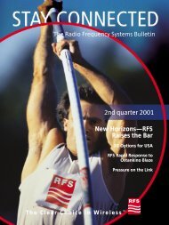
Digital backhaul for<br />
Chinese DTV<br />
A digital upgrade to Shandong Broadcast’s 650-kilometer (400-mile)<br />
microwave backhaul network features total microwave antenna systems<br />
from RFS. The Chinese broadcaster is now one step closer to DTV.<br />
Yishan tower, Shandong province:<br />
more than 30 RFS high-performance<br />
microwave antennas were<br />
deployed throughout<br />
the network.<br />
calculate the interference potential and to<br />
design the radio link network. Other<br />
aspects of the network design involved<br />
allocations of polarization (vertical or<br />
horizontal), frequency and gain for each<br />
point-to-point link.<br />
tower-mounted antennas with the Alcatel<br />
LSY 9600 radio in the equipment room<br />
at the tower base. Featuring superior<br />
transverse stability, flexibility and crush<br />
strength, the FLEXWELL waveguide was<br />
installed in continuous lengths between<br />
With the Chinese government expected<br />
Capacity plus<br />
Long distance hops<br />
50 and 100 meters (164 to 328 feet)—<br />
depending on the height of the<br />
to name a digital television (DTV) broad-<br />
Alcatel Shanghai Bell designed the new<br />
The resulting network utilizes frequency<br />
tower—eliminating flange discontinuities<br />
casting standard by the end of 2005, the<br />
radio link network, based on high-<br />
channels in the 5-GHz band for all links,<br />
and facilitating installation. The premium<br />
nation’s terrestrial broadcasters are starting<br />
performance microwave antenna systems<br />
except for the initial link between Jinan and<br />
version is specially designed for high-<br />
to mobilize and plan for the anticipated<br />
from <strong>Radio</strong> <strong>Frequency</strong> <strong>Systems</strong>. According<br />
the first peak at Juezishan. For this short<br />
capacity radio systems, where low loss and<br />
upgrade to digital services. Some broad-<br />
to Sindy Fei, RFS Area Product Manager for<br />
five-kilometer (3-mile) hop, the 11-GHz<br />
a very low VSWR is required.<br />
casters will need to move fast once<br />
the decision is announced, since analog<br />
Microwave Antenna <strong>Systems</strong>, an important<br />
criteria for the network was that it be<br />
band was used. Most of the hops span<br />
much greater distances, with three of<br />
Total system optimized<br />
switch-off is already scheduled in some<br />
future-proof. “Not only is the new network<br />
around 100 kilometers (62 miles) through<br />
The complete RFS system—from the<br />
provinces for as early as 2008. This means<br />
ready for DTV when it’s launched, but it has<br />
mountainous territory. “These are very long<br />
output of the radio to the antenna—was<br />
they are looking at ways of getting a head<br />
additional capacity built-in as well,” he<br />
distances for digital microwave point-<br />
fully optimized to meet the technical<br />
start—upgrading analog backhaul networks<br />
says. “At some later date it may even be<br />
to-point links,” says Fei, “and they required<br />
specifications determined by Alcatel<br />
to digital is one possible place to begin.<br />
used for Internet services. The existing<br />
some special engineering.”<br />
Shanghai Bell. According Fei, RFS won the<br />
Shandong Broadcast is one such provincial<br />
antenna/radio systems are expandable to<br />
Common techniques used to improve the<br />
contract based on the superior perfor-<br />
broadcaster faced with the 2008 analog<br />
double the current capacity of 155 mbps.”<br />
signal-to-noise ratio for very long hops are<br />
mance of the complete system, which<br />
6<br />
COVER STORY<br />
COVER STORY<br />
7<br />
switch-off deadline. Located on the lower<br />
The upgrade project was conceived in<br />
space and/or frequency diversity. The hop<br />
offers unsurpassed reliability and longevity.<br />
reaches of the Yellow River, the coastal<br />
March 2004, when it became clear that the<br />
essentially consists of two parallel point-to-<br />
“RFS also provided supervision on site to<br />
Shandong Province overlooks the Korean<br />
existing analog microwave backhaul<br />
point links, operating on different channels<br />
ensure the installation team was correctly<br />
Peninsula and the Japan Archipelago. It is<br />
network would not accommodate either<br />
within the band, and separated by a vertical<br />
instructed in how to assemble the system,”<br />
one of China’s more densely populated<br />
the digital capability or the capacity<br />
distance of about 10 meters (33 feet). For<br />
Fei says. “This included mounting of the<br />
provinces, occupying a total area of 156,000<br />
required for DTV. According to Fei, any<br />
the Shandong Broadcast microwave<br />
antenna in the correct position and<br />
square kilometers (60,200 square miles) with<br />
notions of deploying alternative backhaul<br />
backhaul network, a combination of space<br />
techniques for connecting the waveguide.”<br />
a population of over 90 million. As such,<br />
technologies were instantly dismissed: both<br />
and frequency diversity were used for all<br />
Installation took a total of 21 days, with<br />
Shandong is also one of the most developed<br />
the coastal winds and mountainous terrain<br />
hops greater than 35 kilometers (22 miles)<br />
another day for testing and commissioning<br />
provinces, and will be part of the ‘first phase’<br />
of Shandong Province made microwave<br />
in length.<br />
at each site.<br />
of China’s transition to DTV broadcasting.<br />
radio links the most practical and cost-<br />
The RFS antennas used in the installation<br />
The network finally went on-air in April<br />
To gear itself into readiness for DTV,<br />
effective option.<br />
were predominantly 10-foot single-polarized<br />
2005, and is currently supporting the<br />
Shandong Broadcast recently completed an<br />
“It’s a very windy province, due to the prox-<br />
high-performance microwave antennas,<br />
existing analog television services. “The<br />
extensive digital upgrade of its 650-kilometer<br />
imity of the sea,” says Fei. “Therefore RFS<br />
optimized for use in the 5-GHz band<br />
system is performing very well,” says Fei.<br />
(400-mile) micro-wave backhaul network. As<br />
microwave antennas, with their high<br />
(model DA10-44AD). In addition to a<br />
“It has all the capacity it needs and<br />
the maincommunications backbone for the<br />
mechanical standard, were first choice. The<br />
robust and wind-resistant construction,<br />
more. Now Shandong Broadcast is one<br />
broadcaster, the network transmits and dis-<br />
easy and fast installation was an additional<br />
The communications backbone distributes<br />
these antennas feature low voltage<br />
step closer to realizing the full potential<br />
tributes eight television channels from the<br />
advantage, as optical fibers are very difficult<br />
eight television channels from the network<br />
standing wave ratio (VSWR) feed, planar<br />
of DTV.”<br />
network operations center (NOC) in the<br />
to install in mountainous terrain.”<br />
operations center (NOC) in the western<br />
radome, and shroud for improving side<br />
western city of Jinan. The new radio link<br />
Working with Alcatel Shanghai Bell, RFS<br />
city of Jinan.<br />
lobe suppression. More than 30 antennas<br />
comprises 10 point-to-point hops, with<br />
got involved early in the network design<br />
were deployed throughout the network<br />
each tower also a prospective DTV broad-<br />
process, due to the fact that only RFS<br />
in varying combinations of vertical and<br />
cast site. From Jinan, it snakes east across<br />
antennas satisfied the strict radiation<br />
horizontal polarization.<br />
mountainous regions towards the coast,<br />
pattern required by the network planners.<br />
Lengths of RFS FLEXWELL premium<br />
where it terminates near Weihai.<br />
The radiation pattern data were used to<br />
elliptical waveguide EP46J connect the
Get a grip—coaxial<br />
transmission line goes<br />
Premium<br />
Attenuation can provide is by optimizing<br />
wireless data network performance.<br />
Third-generation wireless data services, such<br />
as wideband code division multiple<br />
access (W-CDMA) and CDMA 2000,<br />
present challenging operational constraints.<br />
“The maximum data rates quoted for<br />
Premium attenuation transmission line solutions are finding favor on<br />
mobile base stations across the globe. STAY CONNECTED explores this<br />
generational leap in transmission line technology—what’s on offer, and<br />
the benefits to be had.<br />
cell-based wireless data technologies are<br />
power-limited, so carriers are doing<br />
whatever is possible to maximize the rather<br />
small area of highest data rate reception<br />
surrounding each base station,” he says.<br />
Fig. 1: CELLFLEX ‘A’ Premium Attenuation<br />
3-dB length at 2000 MHz<br />
The business of providing an RF ‘link’<br />
between the base station radio and<br />
the antennas and other base station<br />
personal communications services (PCS)<br />
band. The allocation of higher frequency<br />
spectrum causes the effective cell<br />
“To-date, European carriers’ interest in<br />
CELLFLEX ‘A’ Premium Attenuation has been<br />
driven by the need to extend this area of<br />
‘high data rate’ coverage at each site. This is<br />
Cable size<br />
1-5/8 inch<br />
1-1/4 inch (std)<br />
1-1/4 inch (ultraflexible)<br />
RF equipment atop the tower is almost as<br />
size to shrink and thus places increased<br />
essential, as it helps ensure a healthy and<br />
7/8 inch<br />
old as the science of RF itself. The advent of<br />
the foam-dielectric corrugated co-axial<br />
focus on transmission line loss. “Simply<br />
put, less transmission line attenuation<br />
growing revenue stream.”<br />
RFS Area Product Manager for Transmission<br />
0 20 40 60 80 100<br />
3-dB length in meters (at 2 GHz)<br />
cable in the 1960s was a major milestone in<br />
establishing this link in an electrically-<br />
means more power at the tower top,<br />
which leads to improved performance,<br />
Lines, Matt Gauvin, concurs; pointing out<br />
that the situation is very similar in North<br />
Today's cable<br />
CELLFLEX ‘A‘ Premium Attenuation<br />
efficient and cost-effective manner. Recent<br />
maximized base station spacing and<br />
America. “The demand for premium attenu-<br />
changes in mobile technologies, subscriber<br />
therefore reduced capex and opex,”<br />
ation transmission line in North America is<br />
applications, and spectrum assignment<br />
says Wunder.<br />
driven largely by the ‘bang for your buck’<br />
Fig. 2: CELLFLEX ‘A’ Premium Attenuation—<br />
% attenuation improvement<br />
8 FEEDER SYSTEMS<br />
At 2 GHz<br />
At 1.8 GHz<br />
At 894 MHz<br />
9<br />
have created the need for transmission line<br />
efficiencies once considered unattainable.<br />
The development of latest-generation<br />
premium attenuation transmission line<br />
is the answer to this need, and is an<br />
important milestone in the history of<br />
the foam-dielectric coaxial cable.<br />
The drivers are two-pronged, according<br />
to Gerhard Wunder, Global Product<br />
Counting the cost<br />
At first glance, the attenuation improvements<br />
achieved by of low-loss transmission<br />
line may seem—at least numerically—small,<br />
yet the bottom-line benefits can be huge<br />
(see Figures 1 and 2). “In the case of RFS’s<br />
CELLFLEX ‘A’ Premium Attenuation cable,<br />
we’ve achieved attenuation improvements<br />
of the order of five to eight percent over<br />
imperative,” he says. “Carriers are demanding<br />
a premium ‘performance to price-point’<br />
ratio—there’s clearly a need to provide the<br />
optimal transmission line to maximize<br />
signal-to-noise levels in broadband wireless<br />
data applications. But there is also concern<br />
about mechanical performance—the<br />
message we’re hearing from carriers all over,<br />
is that if they make the move to a premium<br />
% attenuation<br />
improvement<br />
8%<br />
7%<br />
6%<br />
5%<br />
4%<br />
3%<br />
2%<br />
1%<br />
0%<br />
7/8 inch<br />
1-1/4 inch<br />
(ultraflexible)<br />
Cable size<br />
1-1/4 inch (std)<br />
1-5/8 inch<br />
Manager of Transmission Lines with <strong>Radio</strong><br />
conventional transmission line,” Wunder<br />
attenuation transmission line it must show<br />
<strong>Frequency</strong> <strong>Systems</strong>. “The main driver is the<br />
global move from voice-only wireless<br />
services to more data-centric mobile<br />
says. This, he explains, would typically mean<br />
that a cable run of 50 meters could be<br />
extended a further four meters by using<br />
no discernible variation in crush strength and<br />
site handling. This is where CELLFLEX ‘A’<br />
Premium Attenuation really excels—the<br />
Fig. 3: The influence of dielectric loss—<br />
smooth wall cable vs corrugated cable<br />
services,” Wunder explains. “In 3G wireless<br />
data, there is a distinct concern about<br />
network performance—far more so than in<br />
the more-forgiving world of ‘voice-only’.”<br />
The second imperative is that caused<br />
by the relentless drift upward<br />
in allocated spectrum—whether it be<br />
CELLFLEX ‘A’ Premium Attenuation cable,<br />
while still meeting link budget constraints.<br />
Alternatively, on some sites, the designer<br />
could opt for a smaller diameter (read ‘less<br />
costly’) cable.<br />
“If you amortize this over the total number<br />
of sites in a network, including the cost of<br />
cable support infrastructure, there are<br />
crush resistance and handling is essentially<br />
equivalent to conventional CELLFLEX.”<br />
An attenuation perspective<br />
Wunder points out that the bottom-line<br />
cost implications of transmission line<br />
attenuation are still often widely misunderstood.<br />
He suggests a comparison of<br />
Attenuation (dB/100m)<br />
4<br />
3.5<br />
3<br />
2.5<br />
2<br />
1.5<br />
Smooth wall cable<br />
Corrugated cable<br />
to the 2.1-GHz third-generation (3G)<br />
universal mobile telecommunications<br />
significant savings to be had in cable<br />
roll-out costs,” Wunder says. But he believes<br />
transmission line return loss against<br />
attenuation to put this argument in<br />
1<br />
0 500 1000 1500 2000 2500 3000<br />
<strong>Frequency</strong> (MHz)<br />
service (UMTS) spectrum of Europe and<br />
that the most significant return-on<br />
perspective. “Return loss on a transmission<br />
much of Asia, or the Americas’ 1.9-GHz<br />
investment that CELLFLEX ‘A’ Premium<br />
line is a globally used key performance
indicator of the quality of the final<br />
installation,” Wunder says. “It’s a given that<br />
site crews the world over will often spend a<br />
great deal of time—and perhaps even<br />
re-connectorize or re-run a cable—to<br />
ensure the line’s return loss is acceptable.”<br />
compared with conventional 1-5/8-inch<br />
foam-dielectric coaxial feeder,” he says.<br />
“That’s twice the throughput benefit<br />
achieved by ensuring your return loss is up<br />
from 18 to 23 dB—simply by electing to use<br />
Premium Attenuation!”<br />
He points out that the difference between The attenuation ‘attributes’ of rigid<br />
a poor return loss of 18 dB, and the far<br />
more acceptable figure of 23 dB, equates to<br />
smooth-wall feeder cable are, according<br />
to Wunder, another area that is widely<br />
10 FEEDER SYSTEMS<br />
Wunder explains, “a resistive element<br />
and dielectric attenuation element.” The<br />
resistive element is proportional to the<br />
square root of the frequency, while the<br />
dielectric element rises in direct proportion<br />
with frequency. Rigid smooth-wall cables,<br />
Wunder points out, are specifically<br />
designed for use at cable television (CATV)<br />
frequencies (typically 50 to 550 MHz),<br />
rather than the higher frequencies of<br />
mobile wireless networks (see Figure 3).<br />
“The attenuation figures of smooth-wall<br />
cable versus corrugated cable are<br />
relatively close at lower frequencies,<br />
as the dielectric attenuation is insignificant<br />
under these conditions,” he says. “But as<br />
the frequency increases—especially at<br />
1800 MHz, 1900 MHz and beyond—<br />
the poorer quality of dielectric typically<br />
found in commercial smooth-wall<br />
coaxial cables causes a rapid increase in<br />
attenuation.”<br />
This, along with the enormous bending<br />
torques required to work with rigid<br />
of its conventional predecessor, to ensure<br />
the easiest transition for site crews from<br />
‘standard’ to ‘premium’.<br />
An important practicality issue is that<br />
of connectorization, and backward<br />
compatibility of connector stocks. “From a<br />
purchasing department’s perspective,<br />
the whole issue of connector backward<br />
compatibility isn’t a concern—their<br />
simplistic argument is that ‘I buy the<br />
matching connectors with the cable’,”<br />
says Wunder.<br />
But this, he says, is only part of the story.<br />
“The site reality is that connectors can<br />
get misplaced, or are often required on<br />
existing sites to re-connectorize existing<br />
feeder runs. This is why RFS tailored<br />
the dimensions of CELLFLEX ‘A’<br />
Premium Attenuation to ensure backward<br />
compatibility with the existing<br />
RFS RAPID FIT connector series. There’s no<br />
point running a system that requires<br />
three or four different connector series,<br />
plus re-training and re-tooling, just<br />
The path to premium—a carrier’s view<br />
For Australian integrated communications<br />
group, Optus, electing to use a premium<br />
attenuation transmission line solution was<br />
largely driven by the needs of its emerging<br />
3G UMTS mobile network.<br />
A spokesperson for Optus cited the obvious<br />
increase in operating frequency from its<br />
demand within any W-CDMA cell means<br />
that feeder chain losses can potentially<br />
have a significant impact on the available<br />
power per service, plus network capacity<br />
and coverage.<br />
“Low-loss feeder assists in improving the<br />
radio path and achieving the data rates<br />
existing 2G 900-MHz network to the new demanded by customers,” said the<br />
UMTS 2100 MHz as one—but by no means<br />
the only—reason for the move to a low-loss<br />
feeder solution. Equally significant drivers<br />
are the issues of RF power sharing among<br />
users and network optimization.<br />
“With CDMA-based technology, the RF<br />
power is a shared resource among users, as<br />
opposed to 2G/GSM services, where all the<br />
power is available to one user for an instant<br />
spokesperson. “This, in turn, allows cells to<br />
be spaced further apart, [which] reduces<br />
the required cell density, thus saving capex<br />
as well as reducing the opex associated<br />
with maintaining these sites.”<br />
On the subject of selecting an appropriate<br />
low-loss transmission solution, the clear<br />
message is to ensure that the transition<br />
from the legacy cabling system to the new<br />
in time,” the Optus spokesperson said. technology is as uncomplicated and<br />
User services in a 3G network can also vary,<br />
from voice (which has low RF resource<br />
demand), through to high-speed packetswitched<br />
data services which demand<br />
greater amounts of RF power. This<br />
straightforward as possible. “It is critical<br />
that the processes do not change,” the<br />
spokesperson emphasized. “This is with<br />
regards to transmission line handling,<br />
storage and installation practices.”<br />
potentially wide range of RF power 11<br />
an actual transmission improvement of<br />
around 0.05 dB. This stands in stark<br />
contrast with what can be achieved<br />
by electing to use CELLFLEX ‘A’<br />
Premium Attenuation. “A 40-meter run<br />
of 1-5/8-inch CELLFLEX ‘A’ Premium<br />
Attenuation operating at 1800 MHz<br />
will actually provide a transmission<br />
improvement of around 0.1 dB, when<br />
misunderstood. Common around the<br />
world in its native application as a means<br />
of routing cable television signals, the<br />
rigid smooth-wall cable is often thought<br />
to be ‘low attenuation’. The reality can be<br />
explained by the electro-physics of<br />
foam-dielectric coaxial cable.<br />
“The attenuation of any foam-dielectric<br />
coaxial cable is made up of two elements,”<br />
smooth-wall cable, makes it particularly<br />
impractical for applications outside of<br />
trench-based CATV use.<br />
Gauvin notes that the poor attenuation<br />
performance of smooth-wall coaxial<br />
cable at higher frequencies is set to<br />
become more problematic in 2006,<br />
when the US spectrum regulator, the<br />
Federal Communications Commission<br />
(FCC), auctions significant portions of<br />
2.1-GHz spectrum for emerging 3G applications.<br />
“This represents a 10 percent<br />
increase in frequency from regular PCS,”<br />
says Gauvin, “so the issue of attenuation<br />
will become all the more important.”<br />
Practical deciders—<br />
smooth transitions<br />
But it is the practical issues of site<br />
handling, mechanical strength and<br />
reliability that are determining which way<br />
carriers ultimately elect to go in today’s<br />
low-loss feeder stakes. In essence, the<br />
premium attenuation cable needs to<br />
provide the same look, feel and handling<br />
to move from a conventional to a<br />
premium attenuation cable—it’s simply<br />
not site-practical.”<br />
Crush resistance and the general issue of<br />
ease of site handling is also one of the<br />
most significant deciders in selecting<br />
a low-loss transmission line. “When<br />
we developed CELLFLEX ‘A’ Premium<br />
Attenuation we set out to avoid the<br />
installation shortfalls that we’ve seen in<br />
other brands, as these issues impact<br />
dramatically on the total ‘buy and install’<br />
cost,” Gauvin explains. “We’ve made<br />
no compromise at all on the crush strength<br />
of our Premium Attenuation CELLFLEX,<br />
because retention of crush strength and<br />
reliability is an essential on any site. At<br />
the end of the day, there’s simply no cost<br />
saving to be had—attenuation or otherwise—when<br />
a cable fails mechanically<br />
and has to be replaced!”<br />
CELLFLEX ‘A’ Premium Attenuation series—at a glance<br />
When: The complete range of CELLFLEX<br />
‘A’ Premium Attenuation transmission line<br />
was launched in mid-2005<br />
Where: Both feeder cables and associated<br />
connectors are now available globally.<br />
Cable size range: 7/8, 1-1/4 and 1-5/8-inch<br />
cable diameters. The 1-1/4-inch variant is<br />
also available in ‘ultra-flexible’ (UCF) format.<br />
Return loss (VSWR): The CELLFLEX ‘A’<br />
series RAPID FIT connector pair offers<br />
reduced return loss across the range—up to<br />
6-dB improvement at 2.2 GHz.<br />
Intermodulation (IM) performance:<br />
The CELLFLEX ‘A’ Premium Attenuation<br />
series cable and connector pair exhibits<br />
consistently low and stable IM levels.<br />
Attenuation: CELLFLEX ‘A’ Premium<br />
Attenuation series boasts a dramatic<br />
improvement in attenuation performance—typically<br />
between five and eight<br />
percent when compared with conventional<br />
foam-dielectric coaxial cable.<br />
Connector size range: To match all<br />
CELLFLEX ‘A’ series sizes, in both type N<br />
and 7-16 DIN interface.<br />
Jacket options: UV-resistant polyethylene<br />
(J) or flame and fire retardant jackets<br />
(JFN).
RFS in China, for China<br />
As anticipation builds for the eruption of third-generation wireless<br />
communications into China, RFS intensifies its local activities with the<br />
establishment of RF conditioning and base station antenna design and<br />
manufacturing facilities in Shanghai.<br />
Over the past decade, China has become a<br />
growing hub for mobile activity. Every<br />
month the country adds five million mobile<br />
subscribers, which represents a significant<br />
portion of the larger Asia Pacific region’s<br />
wireless market. In response to this growth,<br />
<strong>Radio</strong> <strong>Frequency</strong> <strong>Systems</strong> has expanded<br />
its Chinese engineering and production<br />
capabilities to cater specifically to the<br />
local market.<br />
The Chinese mobile communications<br />
market has been the largest in the world<br />
since 2001. A late-comer to wireless<br />
technology, China now has more wireless<br />
subscribers than fixed. According to Patrick<br />
Nobileau, RFS Vice President Base Station<br />
Antenna <strong>Systems</strong>, the Asian mobile market<br />
is at a very exciting stage just now. “China<br />
is at a juncture where it is building new<br />
networks when the rest of the developed<br />
world is evolving existing networks,”<br />
said Nobileau. “The country is just ‘waiting<br />
for 3G’, and the rest of the region is<br />
watching.”<br />
Now providing local design and<br />
manufacture of base station antennas<br />
and RF conditioning products, RFS<br />
is helping China achieve its network<br />
deployment and optimization goals: to<br />
increase coverage and capacity, improve<br />
QoS, and minimize total lifecycle costs.<br />
“The new facilities bring us geographically<br />
closer to the international and Chinese<br />
base station OEMs,” says Carol Ye,<br />
Area Product Manager RF Conditioning.<br />
“That means we can respond faster, and<br />
more easily, to the requirements of the<br />
world’s most dynamic mobile market.”<br />
Chinese methods<br />
RFS’s newest RF conditioning facility<br />
is based in China’s commercial capital,<br />
Shanghai, and comprises a manufacturing<br />
area of 1800 square meters (19,300 square<br />
feet), plus a research and development<br />
laboratory covering 300 square meters<br />
(3,200 square feet). The facility has been<br />
operating since 2002, and since the<br />
beginning of 2005 has included an R&D<br />
team. The R&D capability was established<br />
to meet the product development needs for<br />
WIRELESS COMMUNICATIONS<br />
The RF conditioning division of RFS China has been providing<br />
12 specific technologies for wireless carriers in China, Taiwan,<br />
13<br />
Vietnam, Indonesia, Pakistan and India.<br />
The RFS base station antenna design and<br />
manufacturing facility in Shanghai currently<br />
produces 60,000 antennas annually.<br />
both OEMs and operators in Asia Pacific<br />
region. “Doing business in China is very<br />
different to what RFS is accustomed to in<br />
Europe orthe US,” says Ye.<br />
According to Ye, the Chinese corporate<br />
culture approaches product development<br />
through a more iterative process than those<br />
used in other parts of the world.<br />
“In the Western world, customers are used<br />
to coming to RFS with specific needs that<br />
are [usually, but not always] defined<br />
through preliminary technical discussions,<br />
and then RFS aims to satisfy those,” she<br />
says. “This generally begins with a set of<br />
specifications set out by RFS and the<br />
customer; is followed up by mutual<br />
discussions on concepts; and culminates<br />
in an RFS prototype—usually within six<br />
weeks.”<br />
In China, on the other hand, the supplier is<br />
expected to be involved a lot earlier in the<br />
development process. “Customers come to<br />
us with loose conceptual specifications<br />
and then discussions begin on what is<br />
actually required. Sometimes three or four<br />
prototypes are developed before the<br />
actual specifications are cemented, so the<br />
technical relationship is of a different<br />
nature. Importantly, all this must still be<br />
completed within a limited number of<br />
weeks,” says Ye.<br />
Having a local engineering team that is<br />
sensitive to regional issues, and can turn<br />
designs around quickly, allows RFS to meet<br />
these stringent deadlines. Most recently,<br />
the RF conditioning division of RFS China<br />
has been providing specific technologies<br />
such as second and third-generation<br />
(2G/3G) diplexers, co-location protection<br />
filters and 3G tower-mount amplifiers for<br />
wireless carriers in China, Japan, Taiwan,<br />
Vietnam, Indonesia, Pakistan and India.<br />
Other interesting research and development<br />
projects focused on transceiver<br />
front-end products—RF modules integrated<br />
within the base station—for major Chinese<br />
OEMs. “As we develop these products<br />
for the Asian market our design engineers<br />
ensure continuity by thoroughly documenting<br />
all solutions,” says Ye. “This builds<br />
strong foundations for future product<br />
development where situations might share<br />
similar characteristics.”<br />
Building a base<br />
The same philosophy has been extended to<br />
the RFS base station antenna design and<br />
manufacturing facility in Shanghai, which<br />
currently produces 60,000 antennas<br />
annually. Operational since October 2004,<br />
this center has the capacity to produce all<br />
cellular antenna models from the RFS highperformance<br />
Optimizer family. “What’s<br />
most in demand in China is the RFS<br />
Optimizer cross-polarized variable electrical<br />
tilt directional panel antenna,” says<br />
Nobileau. “The broadband functionality<br />
of these antennas is highly sought-after by<br />
wireless carriers and OEMs in this region.”<br />
Because of the rapid network growth<br />
across the continent, Chinese carriers are<br />
increasingly confronted with the cellular<br />
challenges faced by network operators<br />
globally: a need for high side-lobe suppression,<br />
superior gain performance and<br />
reduced cell-to-cell interference. At the<br />
same time, there is a need to reduce tower<br />
and tower occupancy costs, to minimize<br />
both roll-out capex and network opex.<br />
“Carriers are opting for the dual polarized<br />
antennas with variable tilt rather than<br />
vertically polarized panel arrays. This is<br />
because you need fewer antennas, and can<br />
therefore reduce the overall cost of tower<br />
structures,” says Nobileau. “It also offers a<br />
reduced visual impact, which is particularly<br />
important in these areas where base<br />
stations are being installed at such a rapid<br />
pace.”<br />
According to Nobileau, these sorts of<br />
matters are easy to resolve when<br />
production and design are on location.<br />
“We can tailor the product, and the<br />
production, to the immediate needs of the<br />
market,” he says. “We’re focusing on what<br />
the customer actually needs in China—3G<br />
and beyond.”
Trouble at the tower top<br />
As the FCC auctions wireless spectrum for future services in the US, the<br />
cocktail of co-located technologies and frequencies at the tower top could<br />
interact with each other in unpredictable ways—spawning unprecedented<br />
interference challenges.<br />
The contemporary demand for communications<br />
mobility is undeniably putting<br />
pressure on wireless spectrum. New<br />
technologies and services—such as WiMAX<br />
and mobile television—are joining<br />
third-generation (3G) cell-based mobile<br />
services in the jostle for bandwidth.<br />
Spectrum regulators are having to assess—<br />
and quickly—how best to reassign and<br />
redeploy spectrum and services to<br />
pave the way for future applications.<br />
An added complexity is the concurrent<br />
trend towards co-location of base station<br />
sites. Premium sites are in high demand,<br />
leading to physical congestion of tower<br />
structures and rooftops, as more and more<br />
antenna systems are deployed. What can<br />
result, says David Kiesling, <strong>Radio</strong> <strong>Frequency</strong><br />
<strong>Systems</strong> Director Marketing and Technical<br />
Services, Americas North, is a cocktail of<br />
frequencies and technologies at the<br />
tower top that interact with each other<br />
in unpredictable ways—in many cases<br />
causing significant interference and<br />
degradation of services.<br />
US spectrum auctions<br />
According to Kiesling, a more widespread<br />
understanding of potential interactions and<br />
interference is required in order to minimize<br />
the impact on quality of service. “There<br />
have been scenarios where a particular<br />
service has been operating successfully for<br />
years, then is suddenly impacted by the<br />
introduction of a new service to the same<br />
site,” he says. “An example of this is<br />
the co-location of 800-MHz CDMA<br />
and GSM 900-MHz services in countries<br />
such as Brazil, China and India.”<br />
The CDMA/GSM co-location scenario is<br />
now well documented, and the solution<br />
has been proven to lie in the deployment of<br />
RF filters with sharp selectivity responses.<br />
However, says Kiesling, the situation in<br />
the United States is about to get very<br />
interesting with the planned 2006 auction<br />
of spectrum in the 1.7 and 2.1-GHz bands,<br />
and later the 2.4-GHz band, by the nation’s<br />
Federal Communications Commission (FCC).<br />
“There’s a very real possibility that carriers<br />
adopting 2.1-GHz spectrum for UMTS<br />
transmission will co-locate with existing<br />
PCS services,” says Kiesling. “If the<br />
antennas are positioned too closely<br />
together on the tower, the third order<br />
intermodulation harmonic created by the<br />
two signals stands to fall in the vicinity<br />
of the 1.7-GHz UMTS receive band.”<br />
(See Figure 1)<br />
WIRELESS COMMUNICATIONS<br />
The problem here is that the intermodulation<br />
signal is likely to be significantly<br />
stronger than the desired receive signals,<br />
leading to problems with blocking and<br />
receiver sensitivity. If the intermodulation<br />
signal falls out of the UMTS receive band,<br />
installation of a RF filter on the UMTS uplink<br />
will mitigate these interfering signals.<br />
However, if the interfering intermodulation<br />
signal happens to fall in-band, the situation<br />
becomes more challenging. Kiesling<br />
suggests that the only recourse for carriers<br />
may be to work together to better manage<br />
frequencies. Equipment vendors will also<br />
be under pressure to ensure their designs<br />
minimize passive intermodulation sources.<br />
Future outlook<br />
This scenario is but one predicted issue<br />
to arise from the assignment of new<br />
spectrum in the US. “The point is that we<br />
don’t know exactly what the outlook is for<br />
the future,” Kiesling says. “Once you’ve<br />
got five different technologies up on the<br />
same tower, you need a certain level of<br />
cooperation and shared knowledge in<br />
order to determine which services will<br />
cause interference to others.”<br />
Kiesling adds that the issue is influenced<br />
by a shifting culture in base station site<br />
ownership: in the US, around 70 percent<br />
of sites are now owned by independent<br />
tower real-estate companies, as carriers<br />
seek to release capital for deployment.<br />
“The site owners don’t necessarily<br />
come from a wireless background and they<br />
don’t necessarily understand all the issues,”<br />
he says.<br />
It all boils down to the fact that someone<br />
needs to take responsibility for how colocated<br />
services interact with each other,<br />
emphasizes Kiesling. In cases where RF<br />
filtering is not an option, this may be as<br />
simple as ensuring certain antennas are not<br />
positioned too close together, or operating<br />
at reduced power levels. The bottom line is<br />
that some degree of care will need to be<br />
taken to avoid trouble at the tower top.<br />
Broadband RF now,<br />
mobile TV later<br />
Impending analog switch-off will provide plenty of<br />
options for broadcasters seeking to utilize the released<br />
spectrum; but how can RF systems be made futureproof<br />
to accommodate the new services?<br />
As analog switch-off dates draw closer in<br />
some parts of the world, the deployment of<br />
digital terrestrial television (DTT) services is<br />
entering a new stage. The focus is starting<br />
to shift towards ‘life after analog’, and the<br />
opportunities that will arise from the<br />
released spectrum. One of the key issues<br />
for broadcasters is the capacity of existing<br />
multi-channel broadcast systems to incorporate<br />
whatever new services might be<br />
introduced—including mobile television.<br />
For those broadcasters deploying new<br />
networks: how can those systems be futureproofed?<br />
Multi-channel systems, where multiple<br />
analog and/or digital services are broadcast<br />
simultaneously from a shared RF broadcast<br />
infrastructure, are common across Europe<br />
and rising in popularity elsewhere. Utilizing<br />
broadband panel arrays and advanced<br />
RF combining technology, such broadband<br />
systems help minimize installation costs and<br />
optimize site real-estate. With little extra<br />
capital expenditure, decisions can be<br />
made now that will make the addition<br />
of future digital services—including<br />
the emerging Digital Video Broadcasting-<br />
Handheld (DVB-H)—easier and less costly.<br />
The future-proof system<br />
A number of important factors need to be<br />
considered when designing a future-proof<br />
system. From a practical perspective, there is<br />
the consideration of signal polarization and<br />
coverage: how likely is it that future services<br />
will have the same requirements as the<br />
existing channels?<br />
This question is particularly pertinent if<br />
DVB-H services are to be considered. It is still<br />
unclear as to whether DVB-H will be<br />
driven by broadcasters or the mobile<br />
telecommunications industry—or whether<br />
these industries are headed towards<br />
some form of convergence or cooperation.<br />
Distribution models utilizing various<br />
frequency bands have been developed by<br />
both parties: some based around mobile<br />
base stations, others based on central<br />
broadcast sites supported by translator sites<br />
in a manner similar to DTT.<br />
The issue of which form of polarization will<br />
provide the best reception for mobile<br />
television handsets deserves further consideration.<br />
In addition, determining optimum<br />
coverage is the subject of an increasing<br />
number of DVB-H trials around the<br />
world. Nevertheless, if the polarization and<br />
coverage requirements of DVB-H are the<br />
same as existing DTT services, it is certainly<br />
possible to use a common infrastructure.<br />
From a system design perspective, the issues<br />
of power handling, voltage capacity, and<br />
whether the combiner chain is able to be<br />
expanded, need to be considered for a<br />
future-proof system. Broadband antennas<br />
are available to cover the full UHF spectrum;<br />
however, the number of channels that the<br />
system can support is dependent on<br />
the power and voltage characteristics.<br />
Importantly, in multi-channel systems the<br />
voltage ratings become critical, plus digital<br />
services exhibit higher peak voltages than<br />
analog services with equivalent power. It is<br />
therefore beneficial if the planned digital<br />
replacement for analog services is factored<br />
into system design at the beginning.<br />
It doesn’t cost much to consider extra<br />
power and voltage handling when<br />
specifying an antenna and feeder system.<br />
Expanding combiners<br />
When it comes to expanding an existing<br />
combiner chain, there needs at the very least<br />
BROADCAST<br />
14 15<br />
Figure 1: The UMTS/PCS<br />
co-location challenge<br />
to be space available. Coaxial combiners—as<br />
most often seen in Europe—can be<br />
rearranged relatively easily to accommodate<br />
new modules, providing there is enough<br />
power and voltage handling in the final<br />
stages. On the other hand, it is far more<br />
difficult to insert channels into a high-power<br />
directional waveguide combiner system; in<br />
such systems, it is advisable to incorporate<br />
‘blanking’ sections into the chain where<br />
additional channels can be inserted later.<br />
However, it is usually necessary to know the<br />
specific channel beforehand, since channel<br />
sequence is important.<br />
Although it is difficult to predict exactly<br />
what technologies are coming down the<br />
track, it is certainly possible—and perhaps<br />
advisable—to build-in extra capacity to<br />
multi-channel broadcast systems with very<br />
little up-front expenditure. At the very least,<br />
broadcasters should consider what services<br />
they plan to introduce in replacement of<br />
analog services, in order to ensure the<br />
system will support them.
Ukraine’s Kievo-<br />
Pecherskaya Lavra in Kiev<br />
Ukraine spreads the<br />
wireless word<br />
One of the fastest growing wireless markets in the world, Ukraine<br />
leans heavily on RFS technologies as the foundation for its nationwide<br />
RF networks.<br />
is a center of pilgrimage<br />
for Orthodox Christians<br />
from all over the world.<br />
digital age,” says Rivkina. “Now we're<br />
happy to be assisting all three carriers in<br />
Ukraine's dynamic telecommunications<br />
market.”<br />
Reputation for reliability<br />
Nine years of collaboration with the<br />
Ukrainian wireless carriers has given RFS a<br />
reputation for first-class quality and short<br />
Russia and CIS, as well as processing the<br />
orders. From a global RFS perspective,<br />
Ukraine is an important market, and that’s<br />
why the RFS name is so established here.”<br />
A large portion of RFS’s success in the<br />
region is due to its ability to meet Ukraine’s<br />
uniquely short delivery time requirements.<br />
In a country that from 2004 to 2005<br />
increased its mobile subscriber base by 110<br />
taken the time to analyze the trends<br />
and identify a series of products to<br />
maximize these fast-maturing networks.”<br />
Recently, both carriers have seen the<br />
value of using RFS’s range of highperformance<br />
boosters from its RF<br />
conditioning family of products. According<br />
to Rivkina, DCC/Astelit, being a new<br />
carrier with a young network, has seen the<br />
delivery times. “In this region—Ukraine,<br />
percent, fast delivery is of the utmost<br />
need for boosters and tower-mount<br />
The first form of wireless communication in<br />
(UMC) and Kyivstar—have continued<br />
Belarus and Moldova—trust is a very<br />
importance. “RFS has manufacturing<br />
amplifiers to increase its network capacity.<br />
Ukraine was a symbolic ‘human chain’<br />
to maintain a duopoly now representing<br />
important part of business, and RFS, with<br />
facilities in Balabanovo, near Moscow, and<br />
“Our customers rely on us to keep<br />
formed by half a million Ukrainians joining<br />
98 percent of Ukraine’s mobile subscriptions.<br />
its local sales partners, has proven itself over<br />
also in France, Denmark, Germany and so<br />
them abreast of new and interesting<br />
hands from the capital Kiev, to Lviv in the<br />
Originally the leading operator, UMC was<br />
and over again,” says Rivkina.<br />
on. So, by leveraging this global framework<br />
technologies. It’s a very open and trusting<br />
west. This occurred on January 22, 1990,<br />
forced in mid-2001 to stop accepting<br />
we can meet any order within the shortest<br />
relationship,” says Rivkina.<br />
and stretched over 500 kilometers<br />
pre-paid subscriptions for a period of<br />
delivery time,” says Rivkina.<br />
RFS regularly delivers presentations on new<br />
(310 miles). The act was in commemoration<br />
three months due to network capacity<br />
An important element of the spectrum of<br />
and next-generation technologies to the<br />
of the anniversary of the proclamation of<br />
problems. This paved the way for Kyivstar<br />
solutions provided by RFS to the Ukrainian<br />
Ukrainian carriers, keeping them up to<br />
Ukrainian independence in 1918.<br />
to take a strong position in the market.<br />
wireless communication sector is CELLFLEX<br />
date with progress in the industry. RFS<br />
Ending in 1920, the period of indepen-<br />
Since then, despite fierce competition<br />
foam-dielectric coaxial cable and acces-<br />
also holds annual installation training<br />
dence was short-lived, and it wasn’t until<br />
between the two, both GSM carriers<br />
sories. The popular and high-performance<br />
courses for the carriers’ subcontractors.<br />
the dissolution of the USSR in 1991, that<br />
have been on par, but their overall<br />
RFS feeder cable forms the backbone<br />
“That’s what sets RFS apart from the<br />
Ukraine finally regained independence.<br />
dominance has been almost unassailable.<br />
to the RF distribution of both UMC and<br />
rest, we go to the source of the issue<br />
With its freedom, the country also took<br />
Other carriers have since looked towards<br />
Kyivstar—and more recently DCC/Astelit.<br />
and work out from there—such as<br />
16<br />
REGIONAL<br />
FOCUS<br />
The Dnepr River is the Ukraine’s most significant<br />
river, and—at 2300 kilometers (1430 miles)<br />
long—one of Europe’s longest.<br />
17<br />
on a series of challenges to begin<br />
the Ukrainian wireless industry, although<br />
providing training to our customers’<br />
upgrading its telecommunications sector.<br />
their success has been limited and, in most<br />
installation service providers,” says Rivkina.<br />
The national telecommunications develop-<br />
cases, transitory. The first to really make its<br />
More than just caring, RFS has the<br />
ment plan led first to the launch of analog<br />
mark in the Ukrainian wireless market<br />
advantage of foresight. “Being a global<br />
mobile telephony (using the Nordic Mobile<br />
has been Turkish Turkcell-backed Digital<br />
organization we have gone through<br />
Telephone (NMT) standard in 1993.<br />
Cellular Communication of Ukraine<br />
all stages of the wireless development<br />
The launch of global system for mobile<br />
(DCC)/Astelit, with its ‘Life’ network.<br />
lifecycle. We’ve found that our experience<br />
communications (GSM) digital networks in<br />
Launched in 2005, DCC/Astelit is the<br />
in Eastern Europe and the rest of the<br />
the 900- and 1800-MHz bands followed<br />
newest GSM carrier in Ukraine and is<br />
wireless world provides an important<br />
closely in 1996. This is also the year that<br />
currently deploying an aggressive network<br />
foundation for our work in Ukraine.”<br />
<strong>Radio</strong> <strong>Frequency</strong> <strong>Systems</strong> began to assist in<br />
roll-out incorporating 2.5 generation<br />
In order to keep abreast of the require-<br />
“Based on the reliability of the RFS trans-<br />
Over the coming five years, the Ukrainian<br />
the country’s roll-out of wireless networks.<br />
technologies. Determined to find a niche<br />
ments of the local operators, RFS<br />
mission lines, the Ukrainian carriers are now<br />
carriers are expected to continue increasing<br />
By 2001, two main GSM carriers had<br />
within this rapidly expanding sector,<br />
The Mikhailovski<br />
operates in the Ukraine through three<br />
starting to look into other RFS technologies<br />
both coverage and capacity of their<br />
secured the majority of the mobile market,<br />
DCC/Astelit has been marketing its<br />
Cathedral in Kiev<br />
sales partners: <strong>Radio</strong>chastotnyie Sistemyi<br />
to modernize their networks,” says Rivkina.<br />
GSM networks. Next on the cards is<br />
seizing more than 90 percent of the<br />
subscriber base between them.<br />
fashionable ‘Life’ brand, which targets<br />
students and young adults. The success of<br />
Ukraine, Stankotechimport and Actek C.<br />
These partners act as RFS’s ‘ears on the<br />
Capped capacity<br />
universal mobile telecommunications<br />
service (UMTS), with the first 3G license to<br />
Three’s a crowd<br />
the ‘Life’ network is all the more significant<br />
in light of Turkcell’s first Ukrainian wireless<br />
ground’, although RFS also maintains a<br />
tight focus on the region. “Ukraine is a very<br />
Of particular interest to the Ukrainian<br />
mobile sector in its current evolutionary<br />
be awarded very soon to the incumbent<br />
fixed line operator, Ukrtelecom, a new<br />
Ukraine’s total mobile subscriber base has<br />
venture in 2001—the ‘Novacell’ network—<br />
important country for us,” says Rivkina.<br />
stage is RFS’s suite of network optimization<br />
player in the mobile market. The company<br />
increased from just two million in 2001, to<br />
which folded within two years.<br />
“We have an area manager completely<br />
products. “Both UMC and Kyivstar are<br />
plans to launch commercial UMTS services<br />
more than 20 million in 2005, equating to<br />
According to Natalia Rivkina, RFS Regional<br />
dedicated to looking after RFS customers in<br />
continually rolling out new networks and<br />
by end-2006. “Just as we’ve been there all<br />
a mobile penetration increase from four<br />
Sales Manager, DCC/Astelit is a very new<br />
Ukraine, Belarus and Moldova. We also<br />
optimizing existing ones. Yet, as the<br />
along for the development of the country’s<br />
percent to nearly 50 percent in just<br />
carrier in the Ukrainian wireless market.<br />
have two customer service coordinators<br />
subscriber numbers increase relentlessly,<br />
2G, we’ll be there also to facilitate Ukraine’s<br />
four years. Over this time, the two main<br />
“RFS has been involved with UMC and<br />
providing technical and commercial<br />
the demand for capacity remains the<br />
transition into 3G,” says Rivkina.<br />
carriers—Ukrainian Mobile Communications<br />
Kyivstar since the beginning of Ukraine's<br />
informational support to RFS customers in<br />
driving factor,” says Rivkina. “We’ve
18<br />
Barcelona is home<br />
to 3GSM 2006<br />
At the 3GSM World Congress in mid-<br />
February 2006, <strong>Radio</strong> <strong>Frequency</strong> <strong>Systems</strong><br />
will exhibit a range of RF solutions designed<br />
to assist wireless carriers to maximize<br />
their bottom line. As third-generation<br />
(3G) deployments escalate, carriers are<br />
demanding base station solutions that<br />
keep capex under control, while taking<br />
cumulative opex into consideration. RFS<br />
systems are designed with this delicate<br />
balance in mind.<br />
Held this year in Barcelona, Spain, the<br />
3GSM World Congress is claimed to be<br />
the world’s largest dedicated mobile technology<br />
showcase. This year, the core<br />
IN TOUCH<br />
themes will be the convergence of<br />
telecoms with media and entertainment,<br />
the evolution of 3G, and strategies for<br />
growth in developing markets.<br />
The new RFS products on display will<br />
be drawn from the company’s key<br />
product sectors—including the base<br />
station antenna, RF conditioning and<br />
confined coverage product suites.<br />
RFS at 3GSM World Congress 2006:<br />
Venue Fira de Barcelona, Montjuic,<br />
Barcelona, Spain<br />
13 to 16 February, 2006<br />
Hall No. 2, Stand No. F30<br />
Metro Budapest gets<br />
wireless coverage<br />
DTF<br />
demystified<br />
at NATE 2006<br />
Early in 2005, Vodafone Hungary completed<br />
For some sections of Metro Budapest,<br />
an installation of radiating cable from the RFS RADIAFLEX ‘Vario’ cable (RLVU<br />
<strong>Radio</strong> <strong>Frequency</strong> <strong>Systems</strong> to provide intunnel<br />
158-50JFNA) was deployed. The RLVU cable<br />
wireless communications in the<br />
Metro Budapest. The new communications<br />
is specially designed to operate over longer<br />
transmission lengths without need of<br />
The National Association of Tower Erectors<br />
(NATE) will hold its annual conference and<br />
system supports Vodafone Hungary’s amplifiers. The service length of a cable can exposition from February 13 to 16, 2006.<br />
global system for mobile communications<br />
(GSM) services in the 900-MHz and<br />
1800-MHz bands, plus third-generation<br />
(3G) universal mobile telecommunications<br />
system (UMTS) services.<br />
be increased by decreasing coupling loss<br />
gradually to the extent necessary for<br />
compensating longitudinal loss. In the RLVU<br />
‘Vario’ cable, this is achieved in stepwise<br />
fashion, where the cable consists of sections<br />
At NATE 2006, <strong>Radio</strong> <strong>Frequency</strong> <strong>Systems</strong><br />
Manager of Technical Services, Charlie<br />
Spellman, will deliver a presentation on the<br />
practical functionality and limitations of<br />
distance-to-fault (DTF) transmission line<br />
Based on its excellent longitudinal of decreasing coupling loss.<br />
testing procedures.<br />
attenuation and coupling loss performance,<br />
RFS’s broadband RADIAFLEX RLKU cable<br />
In the case of metro tunnels where access<br />
may be limited, the ability to use longer<br />
The purpose of Spellman’s presentation is<br />
to demystify the mechanics of the DTF<br />
(RLKU158-50JFNA) was selected to lengths of cable, thereby minimizing the use principle and showcase its diagnostic<br />
provide coverage for 32 metro stations.<br />
Furthermore, the cable jacket features<br />
a guide to ensure the cables are installed<br />
of active equipment, significantly eases<br />
system maintenance. Additionally, both the<br />
RADIAFLEX RLKU and RLVU cables are fully<br />
nature. According to Spellman, DTF testing<br />
techniques are commonly misused in the<br />
field. “The problem is that some carriers are<br />
with the radiating slots at the correct broadband, able to support multiple<br />
orientation. This saved Vodafone Hungary services from TETRA 380 MHz up to<br />
Charlie Spellman,<br />
valuable installation time. UMTS 2100 MHz.<br />
RFS Manager of<br />
19<br />
Technical Services<br />
RFS microwave the safe<br />
path in Arizona<br />
Growing<br />
with Greece<br />
As part of an ongoing transition to digital<br />
technologies, the Arizona Department of<br />
Public Safety is one of a number of western<br />
US state agencies deploying microwave<br />
antenna systems from <strong>Radio</strong> <strong>Frequency</strong><br />
<strong>Systems</strong>. The new digital point-to-point<br />
microwave systems are being purchased<br />
under the Western States Contracting<br />
Alliance (WSCA), for which RFS is the<br />
sole supplier of microwave antennas,<br />
waveguide and related accessories.<br />
Stephen Powles, Telecommunications<br />
Engineer with the Arizona Department of<br />
Public Safety, emphasized the critical<br />
nature of public safety communications<br />
networks, which provide the lifeline for<br />
highway patrol, EMS providers, and<br />
other public safety services. Driven by the<br />
need to accommodate digital dispatching<br />
technology, involving fast and reliable<br />
data transfer, Powles and his team are<br />
steadily upgrading analog microwave<br />
networks to digital.<br />
“We have standardized on RFS as a<br />
supplier of microwave antennas, feed<br />
lines and connectors,” said Powles. “This<br />
has been driven by the high standard<br />
of manufacture, ease of assembly and<br />
maintenance, and overall reliability. Our<br />
riggers requested we make the transition to<br />
RFS. We feel RFS is a better product, and<br />
the fact that it is incorporated into the<br />
WSCA agreement has made things that<br />
much easier.”<br />
Asad Zoberi, RFS Area Product Manager for<br />
microwave antenna systems, explained the<br />
WSCA contract for supply of public safety<br />
communications equipment is available to<br />
all government agencies, sub-agencies and<br />
political non-profit organizations within<br />
WSCA member states. “It means specific<br />
RFS microwave products are pre-approved,<br />
which saves considerable time,” said<br />
Zoberi.<br />
RFS was awarded the WSCA contract in<br />
November 2003 for a three-year period. The<br />
company manufactures a wide range of<br />
microwave antennas to meet the stringent<br />
FCC Category A requirements, and has<br />
made a number of breakthroughs in feed<br />
system design to achieve this performance<br />
in small-diameter antennas.<br />
<strong>Radio</strong> <strong>Frequency</strong> <strong>Systems</strong> says ‘γειάσου’<br />
or ‘hello’—to Greece with the late-2005<br />
establishment of a new Athens-based<br />
facility. Located in the center of Athens,<br />
the new premises will facilitate access<br />
to wireless technology for Greece, Cyprus<br />
and the general Balkan region.<br />
According to Harald Zietz, Director RFS<br />
Hellas, RFS will continue to provide<br />
the Balkan telecommunications industry<br />
with its range of high-performance<br />
RF technologies. “Greece is making a<br />
remarkable and positive impact on<br />
growth in this region,” said Zietz. “The<br />
country is now looking to extend its<br />
coverage of mobile third-generation (3G)<br />
services out of the bigger cities and into<br />
the isles where tourism industry is a strong<br />
driver.”<br />
RFS is able to respond quickly to the<br />
specific regional requirements, and assist in<br />
the expansion of both 2G and 3G<br />
networks. To support this, RFS has also<br />
established a local logistic center to stock<br />
and distribute selected RFS products to<br />
the region.<br />
“Wireless development happened very<br />
quickly here, so now it’s a matter of going<br />
back and filling in the gaps—in buildings,<br />
tunnels and metros, but also out in the<br />
more remote regions,” said Zietz. “RFS has<br />
the ideal solutions for this region now and<br />
in the near future.”<br />
taking a nominal DTF performance level<br />
and applying it as a blanket threshold,” said<br />
Spellman.<br />
Offering some insight into the instrumentation<br />
and componentry, Spellman<br />
will provide a basic guide into set-up<br />
parameters and how these can influence<br />
the test results. He will also uncover the<br />
limitations of the test and how to<br />
adequately leverage the benefits of the<br />
DTF measurement.<br />
Charlie Spellman will be presenting<br />
from 1:00 to 2:00 pm on February 14,<br />
2006, at NATE 2006, Disney’s Coronado<br />
Springs Resort, 1000 West Buena Vista<br />
Drive, Lake Buena Vista, Florida.