WE37&WE46; Flexwell Elliptical Waveguide Connectors
WE37&WE46; Flexwell Elliptical Waveguide Connectors
WE37&WE46; Flexwell Elliptical Waveguide Connectors

You also want an ePaper? Increase the reach of your titles
YUMPU automatically turns print PDFs into web optimized ePapers that Google loves.
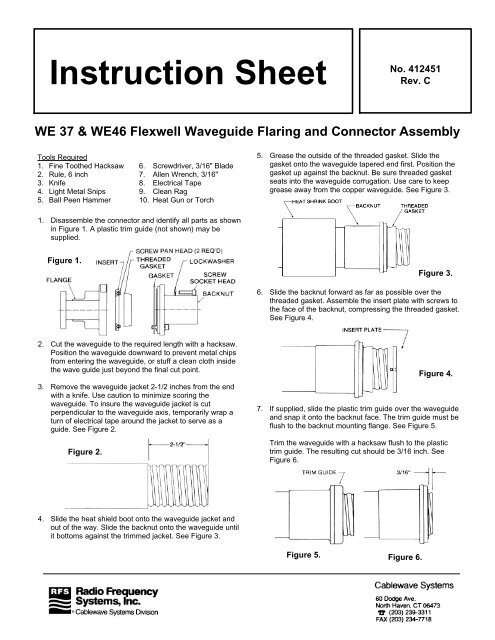
Instruction Sheet<br />
No. 412451<br />
Rev. C<br />
WE 37 & <strong>WE46</strong> <strong>Flexwell</strong> <strong>Waveguide</strong> Flaring and Connector Assembly<br />
Tools Required<br />
1. Fine Toothed Hacksaw<br />
2. Rule, 6 inch<br />
3. Knife<br />
4. Light Metal Snips<br />
5. Ball Peen Hammer<br />
6. Screwdriver, 3/16" Blade<br />
7. Allen Wrench, 3/16"<br />
8. Electrical Tape<br />
9. Clean Rag<br />
10. Heat Gun or Torch<br />
5. Grease the outside of the threaded gasket. Slide the<br />
gasket onto the waveguide tapered end first. Position the<br />
gasket up against the backnut. Be sure threaded gasket<br />
seats into the waveguide corrugation. Use care to keep<br />
grease away from the copper waveguide. See Figure 3.<br />
1. Disassemble the connector and identify all parts as shown<br />
in Figure 1. A plastic trim guide (not shown) may be<br />
supplied.<br />
Figure 1.<br />
Figure 3.<br />
6. Slide the backnut forward as far as possible over the<br />
threaded gasket. Assemble the insert plate with screws to<br />
the face of the backnut, compressing the threaded gasket.<br />
See Figure 4.<br />
2. Cut the waveguide to the required length with a hacksaw.<br />
Position the waveguide downward to prevent metal chips<br />
from entering the waveguide, or stuff a clean cloth inside<br />
the wave guide just beyond the final cut point.<br />
3. Remove the waveguide jacket 2-1/2 inches from the end<br />
with a knife. Use caution to minimize scoring the<br />
waveguide. To insure the waveguide jacket is cut<br />
perpendicular to the waveguide axis, temporarily wrap a<br />
turn of electrical tape around the jacket to serve as a<br />
guide. See Figure 2.<br />
Figure 2.<br />
Figure 4.<br />
7. If supplied, slide the plastic trim guide over the waveguide<br />
and snap it onto the backnut face. The trim guide must be<br />
flush to the backnut mounting flange. See Figure 5.<br />
Trim the waveguide with a hacksaw flush to the plastic<br />
trim guide. The resulting cut should be 3/16 inch. See<br />
Figure 6.<br />
4. Slide the heat shield boot onto the waveguide jacket and<br />
out of the way. Slide the backnut onto the waveguide until<br />
it bottoms against the trimmed jacket. See Figure 3.<br />
Figure 5. Figure 6.
8. Make longitudinal cuts in the waveguide down to the<br />
backnut face with light metal snips. Space the cuts 1/8 to<br />
1/4 of an inch apart, with the narrower spacing being on<br />
the small radii of the ellipse. See Figure 7.<br />
flame to the boot until it shrinks smoothly forming a<br />
weatherproof seal. See Figure 10.<br />
NOTE: The waveguide connector is supplied with two flange<br />
Figure 10.<br />
Figure 7.<br />
9. With a ball peen hammer, flare the waveguide over the<br />
insert plate. Start the flare from the inside and work<br />
outward. Lift with a knife and snip any tab that protrudes<br />
over the gasket groove.<br />
10. When completed,<br />
the flare should be<br />
smooth and flat and<br />
must not protrude<br />
over the gasket<br />
groove. Clean the<br />
backnut face and<br />
waveguide flare of<br />
any grease, dirt or<br />
metal chips. See<br />
Figure 8.<br />
Figure 8.<br />
gaskets, one or both of which are used depending on<br />
the type of interface the connector will be mated to.<br />
CPR series connectors are supplied with a rectangular<br />
shaped full gasket and similar but thinner half gasket.<br />
An O-ring and a round flat gasket are supplied with<br />
UG series connectors.<br />
The following table identifies the proper gasket configuration<br />
to be used with different types of flange installations:<br />
11. Insert the four screws and lockwashers into the backnut's<br />
four thru-holes. Place the flat gasket over the screws and<br />
into the backnut gasket groove. Attach the connector<br />
body to the backnut and tighten the screws securely,<br />
alternating crosswise to insure the body seats even to the<br />
backnut. See Figure 9.<br />
FLANGE<br />
COMBINATION<br />
CPR (G) Contact Flange with<br />
gasket groove mated to an<br />
identical flange.<br />
CPR (G) Contact Flange with<br />
gasket groove mated to CPR (F)<br />
Contact Flange or Pressure<br />
Window without gasket groove.<br />
UG Cover Flange with gasket<br />
groove mated to an identical<br />
flange or UG Choke Flange with<br />
gasket groove.<br />
UG Cover Flange with gasket<br />
groove mated to a UG Cover<br />
Flange or Pressure Window<br />
without gasket groove.*<br />
GASKET(S)<br />
REQUIRED<br />
Full Gasket<br />
Half Gasket<br />
Half Gasket<br />
+ O-Ring<br />
O-Ring<br />
Figure 9.<br />
* UG flanges are available in rectangular or round configurations<br />
dependent on frequency.<br />
12. To complete installation, slide the heat shrink boot into<br />
place over the backnut. Use a heat gun or apply a light