Download catalog - Saint-Tech
Download catalog - Saint-Tech
Download catalog - Saint-Tech

You also want an ePaper? Increase the reach of your titles
YUMPU automatically turns print PDFs into web optimized ePapers that Google loves.
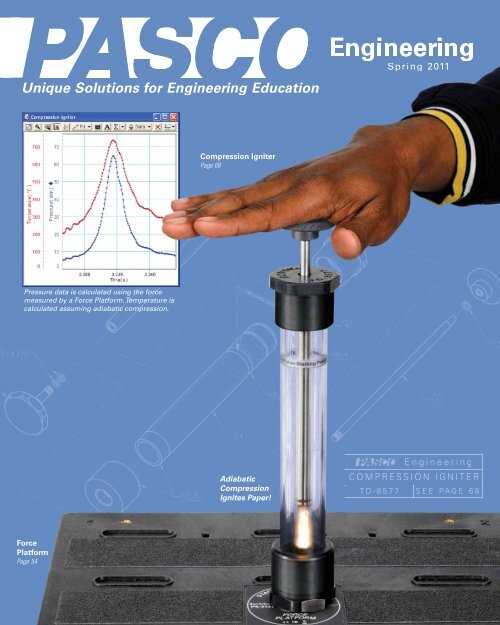
Unique Solutions for Engineering Education<br />
®®<br />
Engineering<br />
Spring 2011<br />
Compression Igniter<br />
Page 68<br />
Pressure data is calculated using the force<br />
measured by a Force Platform. Temperature is<br />
calculated assuming adiabatic compression.<br />
Adiabatic<br />
Compression<br />
Ignites Paper!<br />
Engineering<br />
COMPRESSION IGNITER<br />
TD-8577 SEE PAGE 68<br />
Force<br />
Platform<br />
Page 54
New Products<br />
Density Circulation Model<br />
ME-6816<br />
See page 88<br />
Allows students to model, measure<br />
and understand the complex density<br />
driven circulation associated with heat<br />
transfer through convection.<br />
Blue—<br />
Hotwater<br />
Clear—<br />
Coolwater<br />
Black—<br />
Icecoldwater<br />
Bicycle<br />
Gyroscope<br />
ME-6837<br />
Rotating<br />
Chair<br />
ME-6856<br />
See page 42<br />
New Design<br />
features precision ball<br />
bearings that result in<br />
extremely low-friction for<br />
both the Bicycle Gyroscope<br />
and the Rotating Chair.<br />
Bicycle Gyroscope<br />
Mass Set<br />
ME-6972<br />
See page 42<br />
Modelofsmokerisingbeneathaninversionlayer.Therisingplumeiscausedbyaheatingresistor(notincluded)placedatthebottomofthetank.<br />
MR 100 Analog Breadboard<br />
SE-9981<br />
See page 100<br />
MR 200 Digital/Analog Breadboard<br />
SE-9982<br />
See page 100<br />
Reinventing Edison:<br />
Build Your Own<br />
Light Bulb<br />
SE-7145<br />
See page 98<br />
Reinventing Morse:<br />
Build Your Own Telegraph<br />
SE-7146<br />
See page 98<br />
www.pasco.com/engineering
New Products – Table of Contents<br />
Large Structures Set<br />
ME-7003<br />
See page 18<br />
Baltimore<br />
Truss Bridge<br />
3 m long<br />
Destructible Bridge<br />
Members<br />
ME-7004<br />
See page 13<br />
Metal Plate<br />
Breakable Link<br />
A broken link can be easily<br />
replaced with a new one by<br />
simply sliding it onto the posts.<br />
CI Load Cell Amplifier<br />
CI-6464<br />
See page 9<br />
Build this bridge and<br />
15 other HUGE structures with<br />
this one comprehensive set!<br />
Dual Humidity/Temp/Dew Point<br />
PS-2156<br />
See page 62<br />
Atmospheric Properties<br />
Chamber ME-6813<br />
See page 69<br />
Adjustable Focal<br />
Length Lens<br />
OS-8494<br />
See pages<br />
103, 104<br />
Investigate structural<br />
failure by inserting these<br />
breakable links into your<br />
structures.<br />
www.pasco.com/engineering<br />
DATA ACQUISITION ...................................2-7<br />
Computer Interfaces and Sensors .......2-5<br />
Graphing Datalogger .....................................6-7<br />
STRUCTURES SYSTEM .......................8-20<br />
MATERIALS ...........................................................21<br />
STATICS .............................................................22-25<br />
MECHANICS .................................................26-55<br />
Carts and Tracks ........................................ 26-31<br />
Projectile Motion ....................................... 32-33<br />
Springs and Resonance ........................ 34-39<br />
Rotation ............................................................ 40-43<br />
Energy ............................................................... 44-51<br />
Human Body Mechanics ...................... 52-55<br />
BIOLOGY ...........................................................56-60<br />
ENVIRONMENTAL ..................................61-65<br />
CHEMICAL ENGINEERING ...........66-67<br />
THERMAL .........................................................68-83<br />
Gas Laws......................................................... 68-69<br />
Temperature Sensors ............................. 70-71<br />
Heat Conduction ........................................ 72-73<br />
Equivalent of Heat ..................................... 74-75<br />
Thermal Expansion ................................... 76-77<br />
Thermoelectric ............................................ 78-79<br />
Thermal Radiation ............................................ 80<br />
Heat Engines................................................. 81-83<br />
FLUIDS .................................................................84-89<br />
Bernoulli .......................................................... 84-85<br />
Atmospheric Pressure .................................. 86<br />
Density .............................................................. 87-89<br />
CIRCUITS .......................................................90-101<br />
Electromagnetism ..................................... 90-93<br />
Coils ........................................................................... 94<br />
Electric Field Mapping .................................. 95<br />
Electrostatics ...................................................... 96<br />
Resistance ............................................................ 97<br />
Circuits............................................................98-101<br />
OPTICS ......................................................... 102-105<br />
Optics Bench .....................................................102<br />
Lenses ....................................................................103<br />
Human Eye Model ..........................................104<br />
Diffraction ............................................................105<br />
LAB SUPPLIES .................................... 106-109<br />
Mechanical Supplies ......................... 106-107<br />
Rods and Clamps .................................. 108-109<br />
Index .............................................................. 110-112<br />
Contact Information ....Inside back cover<br />
1
Data Acquisition—ScienceWorkshop ®<br />
PASCO’s Most Powerful Interface<br />
ScienceWorkshop ® 750<br />
Computer Interface - USB<br />
CI-7650<br />
Uses PASCO’s<br />
DataStudio ®<br />
Software<br />
(See page 4)<br />
P Fast: 250,000 Hz<br />
P Built-in function generator<br />
P Built-in DC power supply (300 mA, ±5 V)<br />
P Accessory Power Amplifier (CI-6552A)<br />
increases power to 1 A, ±10 V<br />
P DataStudio Lite included<br />
P NI LabVIEW compatible<br />
Order Information:<br />
750 Interface - USB ..........................................................CI-7650<br />
(USB-compatible computers)<br />
DataStudio Software Site License .......................CI-6871G<br />
Power Amplifier (not shown) ...................................CI-6552A<br />
AC/DC Circuit Board<br />
(See page 101)<br />
Over 45 ScienceWorkshop Sensors Available<br />
P Analog sensors<br />
P Signal conditioning built-in<br />
P Sturdy cases for easy<br />
mounting<br />
Acceleration<br />
CI-6558<br />
Barometer<br />
CI-6531A<br />
Carbon Dioxide<br />
CI-6561<br />
Charge<br />
CI-6555<br />
CI Load Cell Amplifier NEW CI-6464<br />
Colorimeter<br />
CI-6747<br />
Conductivity<br />
CI-6729<br />
Current<br />
CI-6556<br />
Current, High<br />
CI-6740<br />
Dissolved Oxygen<br />
CI-6542<br />
Drop Counter<br />
CI-6499<br />
EKG<br />
CI-6539A<br />
Flow Rate<br />
CI-6730A<br />
Force<br />
CI-6537<br />
Force, Economy<br />
CI-6746<br />
Force Platform<br />
CI-6461<br />
Freefall Adapter<br />
ME-9207B<br />
G-M Tube<br />
SN-7927A<br />
Heart Rate<br />
CI-6543B<br />
Humidity, Relative<br />
CI-6559<br />
Ion Probes<br />
Ion-Selective Electrode<br />
Amplifier Box<br />
CI-6738<br />
Laser Switch<br />
ME-9259A<br />
Light<br />
CI-6504A<br />
Light, Broad Spectrum CI-6630<br />
Light, High-Sensitivity CI-6604<br />
Light, Infrared<br />
CI-6628<br />
For sensor specifications, visit<br />
www.pasco.com/engineering/data-acquisition<br />
Light, UVA<br />
CI-9784<br />
Magnetic Field<br />
CI-6520A<br />
Motion Sensor II<br />
CI-6742A<br />
Oxygen Gas<br />
CI-6562<br />
pH<br />
CI-6507A<br />
Photogate, Accessory ME-9204B<br />
Photogate Head<br />
ME-9498A<br />
Photogate/Pulley System ME-6838A<br />
Pressure Sensor— Absolute CI-6532A<br />
Pressure Sensor—Low CI-6534A<br />
Respiration Rate<br />
CI-6535<br />
Rotary Motion<br />
CI-6538<br />
Sound<br />
CI-6506B<br />
Temperature<br />
CI-6605A<br />
Temperature, High Accuracy CI-6525<br />
Temperature, High,<br />
Type K Probe<br />
CI-6536<br />
Temperature with<br />
Type K Probe<br />
CI-6526<br />
Thermistor Temperature CI-6527A<br />
Thermocline<br />
CI-6731<br />
Time-of-Flight Accessory ME-6810<br />
Voltage<br />
CI-6503<br />
Motion Sensor II<br />
(CI-6742A)<br />
Rotary Motion (CI-6538)<br />
CI Load Cell Amplifier<br />
CI-6464<br />
This amplifier allows users of the 500<br />
and 750 ScienceWorkshop Interfaces to<br />
collect data using the Structures System<br />
100N and 5N Load Cells. This system has<br />
been successfully used at sample rates<br />
up to 10,000 Hz. The sample rate limit<br />
is determined by the interface and<br />
computer used.<br />
A separate amplifier is required for<br />
each load cell.<br />
See page 9 for more information.<br />
Order Information:<br />
CI Load Cell Amplifier* ...............CI-6464<br />
Required for Use:<br />
ScienceWorkshop Interface<br />
Load Cell 100N* .................................PS-2200<br />
Load Cell 5N* .......................................PS-2201<br />
*Patents pending<br />
Photogate/Pulley<br />
System<br />
(ME-6838)<br />
2<br />
www.pasco.com/engineering
Data Acquisition—ScienceWorkshop ® 3<br />
Use ScienceWorkshop<br />
Sensors with NI ELVIS <br />
and LabVIEW <br />
NI ELVIS Adapters for<br />
PASCO Sensors<br />
To collect data, plug an Analog or Digital<br />
Adapter into the prototyping board and<br />
insert a sensor. Connect the adapter to<br />
the appropriate I/O ports on ELVIS and the<br />
system is ready to use.<br />
Once data has been collected, students can<br />
use the power and flexibility of LabVIEW<br />
software to display and condition the<br />
data as needed. This system provides the<br />
perfect opportunity for students to learn<br />
about digital and analog data processing<br />
techniques.<br />
Use ScienceWorkshop sensors in your own<br />
circuits without a computer interface<br />
CI Sensor Voltage Monitor<br />
CI-6611<br />
P Take advantage of PASCO’s numerous fine quality sensors already<br />
mounted in a case and ready to use<br />
Plug up to five ScienceWorkshop sensors at<br />
a time into the front of the CI Sensor Voltage<br />
Monitor. The sensors’ output voltages are<br />
accessed at the buss on the back of the<br />
CI Sensor Voltage Monitor.<br />
Back<br />
Force Sensor<br />
(See page 2)<br />
Fan Accessory<br />
(See page 30)<br />
Front<br />
Force Sensor<br />
Force Accessory<br />
Bracket<br />
Dynamics System<br />
(See page 27)<br />
Voltage reading is<br />
proportional to the<br />
force applied<br />
Sensor plugs into<br />
CI Sensor Voltage<br />
Monitor<br />
1 kg<br />
mass<br />
The NI ELVIS and LabVIEW software are used to control<br />
the Fan Accessory based on measurements from the Force<br />
Sensor.<br />
Analog NI ELVIS<br />
Adapter<br />
CI-6718<br />
CI Sensor Voltage Monitor<br />
Output voltage from sensor<br />
Digital NI ELVIS<br />
Adapter<br />
CI-6719<br />
(Used with<br />
Photogates,<br />
Motion Sensor, and<br />
Rotary Motion Sensors).<br />
NI ELVIS combines instrumentation, data<br />
acquisition and a prototyping board in one unit.<br />
For more information on NI LabVIEW and<br />
NI ELVIS, visit www.ni.com.<br />
Virtual instruments for using PASCO sensors<br />
are available FREE at www.pasco.com/labview.<br />
Use these VIs to get started or modify them to<br />
fit the needs of your laboratory.<br />
Order Information:<br />
Analog NI ELVIS Adapter ...................CI-6718<br />
Digital NI ELVIS Adapter ....................CI-6719<br />
The CI Sensor Voltage Monitor accepts any ScienceWorkshop CI sensor, supplies power to<br />
the sensor, and gives access to the output voltage of the sensor through the terminal strip<br />
on the back of the box. Monitor the output voltage using a voltmeter or an oscilloscope or<br />
wire the sensor output directly into your own circuit. The instruction sheet includes calibration<br />
data for relating the output voltage to the sensor reading (for example, 8 V = 50 Newtons for<br />
a Force Sensor).<br />
Includes<br />
CI Sensor Voltage Monitor<br />
Power Adapter: 9 VDC @ 500 mA<br />
Calibration Data in Manual<br />
Order Information:<br />
Specifications<br />
Accepts all ScienceWorkshop Sensors<br />
5 Voltage Outputs<br />
Power adapter: 9 VDC, 500 mA<br />
Not compatible with PASPORT sensors.<br />
CI Sensor Voltage Monitor ............................................................................................................................. CI-6611<br />
Recommended:<br />
Any ScienceWorkshop Sensor .................................................................................................................... See page 2<br />
Basic Digital Multimeter ................................................................................................................................... SE-9786A<br />
www.pasco.com/engineering
Data Acquisition—PASPORT ®<br />
Hand-held Computer with Interface<br />
XplorerGLX ®<br />
PS-2002<br />
P Includesavoltageprobe,twotemperatureprobes,abuilt-in<br />
speakerandmicrophone,andsignalgenerator<br />
P FourportsforPASPORTsensors<br />
P PrintsdirectlytoselectHPUSBprinters<br />
P UseasaUSBinterfacewhenconnectedtoacomputer<br />
XplorerGLX<br />
(PS-2002)<br />
PASPORT<br />
Interfaces<br />
Work Together<br />
Use any combination<br />
of PASPORT Interfaces<br />
together by plugging the<br />
interfaces into multiple<br />
USB ports or a USB hub.<br />
Order Information:<br />
Xplorer GLX............................................................................PS-2002<br />
Xplorer GLX Power Amplifier...................................PS-2006 p. 7<br />
Connect One PASPORT Sensor<br />
to a Computer<br />
USBLink<br />
PS-2100A<br />
P DirectlylinkonePASPORT<br />
sensortoaUSBport<br />
P Usemultiplelinksfor<br />
moresensors<br />
P 1000Hzmaximum<br />
samplingrate<br />
withPASPORT<br />
sensors<br />
Connect Two PASPORT Sensors<br />
to a Computer<br />
PS-2009<br />
P TwoPASPORTsensorports<br />
P Built-inTemperatureandVoltage<br />
SensorswithProbes<br />
P SimpleUSBconnectivity<br />
tocomputer<br />
P Ruggedpolycarbonatecase<br />
case<br />
P PoweredthroughUSBport<br />
Order Information:<br />
USB Link ................................................................................................PS-2100A<br />
Connect Three PASPORT Sensors to a Computer<br />
USBPowerLink<br />
PS-2001<br />
P Idealforexperimentsusingmultiplesensors<br />
P ThreesensorportsinoneUSBconnection<br />
P 1000HzmaximumsamplingratewithPASPORTSensors<br />
P Built-inUSBhub<br />
Desktop or Field Use. PowerLink functions as a computer-based interface<br />
when connected to a USB port, and can also collect data in the field using<br />
a laptop computer. Includes sensor extension cable.<br />
Order Information:<br />
PowerLink..................................................................................................PS-2001<br />
Order Information:<br />
SPARKlink......................................................................................................PS-2009<br />
USBConnectiontoComputer<br />
LongBatteryLife<br />
Two “C” batteries<br />
(not included) will<br />
provide several days<br />
of use in the field.<br />
4<br />
PASCO’s DataStudio ® Software<br />
P ControlsScienceWorkshopandPASPORTInterfaces<br />
P Powerfuldataanalysistools<br />
P Curve-fitting<br />
P Built-incalculator<br />
P Oscilloscopemodesupportsuptofivetraces<br />
P FunctionGeneratorforScienceWorkshop750Interface<br />
P WindowsandMACcompatible<br />
Gotowww.pasco.com/datastudioformoreinformation.<br />
Order Information:<br />
DataStudio Software<br />
Single User....................................CI-6870G<br />
Site License..................................CI-6871G<br />
www.pasco.com/engineering
Data Acquisition—PASPORT ® 5<br />
Over 70 PASPORT Sensors Available<br />
P PASPORTDigitalSensors<br />
P Self-identifying<br />
For sensor specifications, visit<br />
www.pasco.com/engineering/data-acquisition<br />
AnalogAdapter PS-2158 <br />
3-AxisAcceleration/Altimeter PS-2136 p.55<br />
3-AxisAcceleration PS-2119 p.55<br />
2-AxisAcceleration PS-2118 <br />
Accelerometer-Visual PS-2128 p.30<br />
BreathRate PS-2187 p.56<br />
CarbonDioxideGas PS-2110 p.58,63<br />
Charge PS-2132 <br />
Chemistry PS-2170 p.66<br />
Colorimeter PS-2121 p.67<br />
Conductivity PS-2116A p.67<br />
Current(High) PS-2193 p.94<br />
CurrentProbeNEW PS-2184 <br />
DigitalAdapter PS-2159 p.7<br />
DisplacementSensor PS-2204 p.8,15<br />
DropCounter PS-2117 p.67<br />
DualLoadCellAmplifier PS-2205 p.9<br />
DualLoadCellAmplifierSet PS-2206 p.9<br />
EKG PS-2111 p.57<br />
Ethanol PS-2194 p.58,63<br />
FlowRate/Temperature PS-2130 p.65<br />
Force PS-2104 p.25<br />
Force(HighResolution) PS-2189 p.91<br />
ForcePlatform PS-2141 p.54<br />
ForcePlatform(2-axis) PS-2142 p.54<br />
FreefallAdapter ME-9207B p.2<br />
Galvanometer PS-2160 <br />
Geiger-Muller SN-7927A <br />
GeneralScience PS-2168 <br />
Goniometer PS-2137 p.56<br />
GPSPosition PS-2175 p.6,61<br />
HeartRate(Exercise) PS-2129 <br />
HeartRate(HandGrip) PS-2186 p.57<br />
Humidity/Temp/DewPoint PS-2124A <br />
Humidity/Temp/DewPoint–DualNEW PS-2156 p.62<br />
LaserSwitch ME-9259A p.35<br />
Light PS-2106A <br />
Light(BroadSpectrum) PS-2150 <br />
Light(HighSensitivity) PS-2176 p.105<br />
Light(Infrared) PS-2148 <br />
LightLevel<br />
PS-2177<br />
Light(UVA) PS-2149 <br />
LoadCell&AmplifierSet PS-2199 p.9<br />
LoadCell,5N PS-2201 p.9<br />
LoadCell,100N PS-2200 p.9<br />
MagneticField PS-2112 <br />
MagneticField(2-axis) PS-2162 p.94<br />
Motion(Ultra-SonicPositionSensor) PS-2103A p.20,25<br />
Oxygen,Dissolved PS-2108 p.59<br />
OxygenGas PS-2126A p.58<br />
pH PS-2102 p.66<br />
pHFlatElectrode PS-2182 <br />
pH/ORP/ISE PS-2147 <br />
Photogate,Accessory ME-9204B <br />
(RequiresDigitalAdapter)<br />
PhotogateHead ME-9498A p.44<br />
(RequiresDigitalAdapter)<br />
Pressure-Absolute<br />
PS-2107<br />
Pressure-Barometer/LowPressure PS-2113A <br />
Pressure-Dual PS-2181 p.82<br />
Pressure-Quad PS-2164 p.84<br />
Pressure-Relative PS-2114 <br />
Pressure/Temperature PS-2146 p.69<br />
Relay CI-6462 p.7<br />
RespirationRate PS-2133 <br />
RotaryMotion PS-2120 p.40<br />
Salinity PS-2195 p.62<br />
SoilMoisture PS-2163 p.62<br />
SoundLevel PS-2109 <br />
Spectrometer PS-2635 p.6,60<br />
Spirometer PS-2152 p.56,84<br />
Temperature PS-2125 p.70<br />
Temperature-Array PS-2157 p.71<br />
Temperature-FastResponse PS-2135 p.70<br />
Temperature-Quad PS-2143 p.70<br />
Temperature-Skin/Surface PS-2131 p.70<br />
Temperature-StainlessSteel PS-2153 p.70<br />
Temperature-TypeK PS-2134 p.71<br />
Temperature-TypeK-4port PS-2127 p.71<br />
Temp/SoundLevel/Light PS-2140 <br />
Temperature-Non-contact PS-2197 p.64<br />
Thermocline PS-2151 p.65<br />
Time-of-FlightAccessory ME-6810 p.32<br />
(RequiresDigitalAdapter)<br />
<br />
Turbidity PS-2122 p.65<br />
UVA PS-2149 <br />
Voltage/Current PS-2115 p.78<br />
Voltage(1MHz2-channel) PS-2190 p.7<br />
WaterQuality PS-2169 p.64<br />
WaterQualityColorimeter PS-2179 p.65<br />
Weather PS-2154A <br />
Weather/AnemometerSensor PS-2174 p.61<br />
WindVelocityAccessory<br />
ME-6812<br />
CurrentProbe<br />
PS-2184<br />
The PS-2184 attaches<br />
to a PASCO voltage sensor<br />
to allow the measurement of current between -4 A and +4 A.<br />
The probe contains a precision 0.10 ohm resistor and allows<br />
the precise measurement of the<br />
voltage drop across the resistor.<br />
The current is<br />
measured<br />
by creating a<br />
DataStudio<br />
calculation: I=V/R.<br />
Specifications<br />
Current<br />
Resistor: 0.10 Ohm, 3.0W, 1.0%<br />
Maximum Current: 4A<br />
Maximum Voltage: 10V<br />
Maximum Voltage Without Damage: 30V<br />
Terminals: 4mm Banana Jacks<br />
The current is calculated from the voltage<br />
across the precision 0.10 ohm resistor.<br />
Order Information:<br />
Current Probe..........................................................................................PS-2184<br />
Current<br />
Voltage<br />
Sensor<br />
(notincluded)<br />
www.pasco.com/engineering
Data Acquisition—PASPORT ®<br />
Special Features of the Xplorer GLX ®<br />
1. Remote Datalogging<br />
Take data anywhere, anytime with the Xplorer GLX. Display and analyze the data on<br />
the Xplorer GLX screen. Later, just connect the Xplorer GLX to the USB port on your<br />
computer and all stored data can be downloaded ready for writing reports or further<br />
analysis. Data can also be stored on a USB flash drive and printed<br />
directly to many HP printers.<br />
Equipment Shown:<br />
Rocket Engine Test Bracket.......................................ME-6617<br />
Xplorer GLX.............................................................................PS-2002<br />
Force Sensor..........................................................................PS-2104<br />
Lab Stand..................................................................................PS-2526<br />
See.pages.108-109.for.rods.and.clamps.<br />
The Xplorer GLX is shown with the Rocket Engine<br />
Test Bracket attached to a Force Sensor. Students<br />
can measure and graphically display the impulse of<br />
Estes and other model rocket engines.<br />
2. Record Latitude and Longitude<br />
of Sensor Measurements<br />
GPS.Position.Sensor<br />
PS-2175<br />
The GPS Position sensor utilizes satellite triangulation<br />
to determine the sensor’s position and velocity<br />
in outdoor environments. Obtain sensor data<br />
simultaneously linked to your latitude, longitude,<br />
altitude, and velocity. Pinpoints your location in the<br />
world and reports the latitude and longitude with a<br />
resolution of 2 meters. This data can be imported<br />
into My World GIS software to overlay sensor data<br />
on maps or aerial photos. Relative Position Mode<br />
enables a higher resolution (0.2 meters), suitable<br />
for experiments involving bicycles or people running<br />
or walking, in which the position in the world is not<br />
required.<br />
3. Display Full-scan Spectra with<br />
Ocean Optics Red Tide Spectrometer<br />
Emission.Spectrometer.System.for.Xplorer.GLX<br />
PS-2635<br />
P .Uses.Ocean.Optics.Red.Tide.Spectrometer<br />
P .Full-scan.spectroscopy.without.a.computer!<br />
The Xplorer GLX controls the Ocean Optics Red Tide<br />
Spectrometer which detects the spectrum using a 2048<br />
pixel CCD linear array. The Xplorer GLX does a full sweep<br />
in less than 1 second.<br />
Specifications<br />
Range: VIS-NIR, 350-1000 nm<br />
Optical Resolution: 2 nm<br />
Includes<br />
Ocean Optics Red Tide Spectrometer<br />
Fiber Optics Cable<br />
USB Cable<br />
License key for Ocean Optics GLX feature set<br />
Car acceleration was measured with an Acceleration Sensor, and position and velocity were<br />
measured with the GPS Position sensor, then plotted on an aerial photo in My World software.<br />
The size of the plotted data point indicates the speed of the car, and the data is color<br />
coded to indicate the car’s centripetal acceleration.<br />
Order Information:<br />
GPS Position Sensor......................................................................... PS-2175<br />
Recommended:<br />
3-Axis.Acceleration.Altimeter.................................................... PS-2136..<br />
My.World.GIS.Software.Student.License.......................... SE-7382C.<br />
(For.volume.licensing,.see.www.pasco.com/myworld/)<br />
Light from a Hydrogen tube is sampled using<br />
the fiber optics cable connected to the Ocean<br />
Optics Spectrometer. The Spectrometer is<br />
plugged into the USB port on the Xplorer GLX.<br />
(Light Source sold separately.<br />
Absorption Spectrometer System<br />
for Xplorer GLX on page 66.<br />
Order Information:<br />
Emission Spectrometer System for Xplorer GLX.....................................PS-2635<br />
Required:<br />
Xplorer.GLX..........................................................................................................................PS-2002.<br />
Shown in use with::<br />
Spectral.Tube.Power.Supply...................................................................................SE-9460.<br />
Hydrogen.Tube...................................................................................................................SE-9461.<br />
6<br />
www.pasco.com/engineering
4. Control a Relay Using Xplorer GLX<br />
Calculator Functions<br />
Relay<br />
CI-6462<br />
Data Acquisition—PASPORT ®<br />
The Xplorer GLX controls the Relay<br />
to turn a light on when the temperature<br />
sensor above the bulb reads less than<br />
25 °C. Shown in use with EM-8678<br />
Charge/Discharge Circuit (see page 101).<br />
7<br />
P .Single-pole.<br />
Double-throw.switch<br />
P .Use.with.Xplorer.GLX.Interface<br />
P .For.Sense.and.Control.projects<br />
Order Information:<br />
Relay.....................................................................................................CI-6462<br />
Required for use with Xplorer GLX:<br />
Digital.Adapter...............................................................................PS-2159.<br />
5. Power and Measure Circuits<br />
Power.Amplifier.for.the.Xplorer.GLX<br />
PS-2006<br />
P .Amplifies.the.signal.output.from.the.Xplorer.GLX<br />
P .Built-in.current.sensor<br />
P .10.V,.1.A<br />
P .Signals.available:<br />
DC,.Sine,.Square,.<br />
Triangle,.Sawtooth<br />
1.MHz.2-channel.Voltage.Sensor<br />
Measure two channels simultaneously at up to<br />
1 MHz sampling rate. It has three gain settings with fullscale<br />
input ranges of ±10 V, ±1 V, and ±0.1 V.<br />
Xplorer.GLX.Power.Amplifier<br />
Generate an AC signal to power the RLC<br />
circuit.<br />
Graph shows driving voltage and voltage<br />
drop across the resistor.<br />
Control the output signal from the GLX<br />
Power Amplifier and monitor<br />
all measurements directly from<br />
the Xplorer GLX.<br />
1.MHz.2-channel.<br />
Voltage.Sensor<br />
PS-2190<br />
For more experiments<br />
using the GLX<br />
Power Amplifier<br />
see pages 29 and 37.<br />
P .Measure.two.channels.at.sample.<br />
rates.up.to.1.MHz.<br />
Use the Xplorer GLX and the PS-2190<br />
1 MHz Voltage Sensor to measure the<br />
phase shift between the driving voltage<br />
and the resulting current in an RLC Circuit.<br />
Compare the voltage drop across the<br />
resistor to the voltages across the inductor<br />
and capacitor. All measurements can be<br />
made directly using the displays and tools<br />
included with the Xplorer GLX.<br />
Specifications<br />
Two differential channels<br />
1 MHz max sample rate<br />
± 10 V max input<br />
Three gain settings<br />
Overvoltage protection<br />
The CI-6512 RLC Circuit Board is perfect for studying introductory<br />
AC circuit theory. Vary all parameters, including resistance, capacitance,<br />
and even the inductance of the coil by using the included iron core.<br />
Order Information:<br />
Xplorer GLX<br />
Power Amplifier.................................................PS-2006<br />
1 MHz 2-channel<br />
Voltage Sensor....................................................PS-2190<br />
Required for use:<br />
Xplorer.GLX............................................................PS-2002. p..4.<br />
Recommended:<br />
RLC.Circuit.Board..............................................CI-6512. p..101.<br />
Short.Patch.Cords.............................................SE-7123. .<br />
www.pasco.com/engineering
Structures System – Overview<br />
Structures Overview<br />
Experience real-world design building a large variety of structures. This reconfigurable<br />
system allows students to measure static and dynamic forces using load cells, and<br />
still have time to redesign and test again. See the following pages for ordering<br />
information, and details on individual structures sets.<br />
Numerical displays of load cell forces are generated in PASCO’s<br />
DataStudio® software.<br />
See page 4.<br />
Load Cell & Amplifier Set<br />
See page 9<br />
Measure support forces<br />
with a Force Platform<br />
Measure the support forces of a crane by connecting<br />
it to a Force Platform (PS-2141) using the special<br />
Force Platform Structures Bracket (ME-6988A). The<br />
Force Platform is supported by four individual load<br />
cells which combine to measure the total vertical<br />
force on the platform. These four readings can also<br />
be viewed separately, to measure the unequal forces<br />
on the crane supports.<br />
Tower.Crane<br />
2.3 m tall<br />
Large Slotted<br />
Mass Set<br />
See page 107<br />
Motion Sensor<br />
See page 5<br />
Xplorer GLX®<br />
Hand-held Computer<br />
See page 4<br />
Specifications<br />
Maximum Travel: 10 mm N to +100 N<br />
Maximum Sample Rate: 5 Hz<br />
Resolution: 0.013 mm (0.0005 in)<br />
Displacement of the bridge is measured by the<br />
Xplorer GLX and the Motion Sensor as the 1/2 kg<br />
masses are added to the mass hanger.<br />
Measure bridge deflection with a<br />
Displacement Sensor<br />
The PS-2204 Displacement Sensor measures<br />
the travel of a spring-loaded indicator pressed<br />
against a bridge as the bridge is loaded. It<br />
consists of a PASPORT sensor which plugs<br />
into the included Digital Indicator, a digital<br />
travel indicator which has its own digital LED<br />
readout and can be used as a stand-alone<br />
device. When the PASPORT sensor is plugged<br />
into a PASPORT interface, the reading can be<br />
recorded.<br />
See page 15 for more uses.<br />
Order Information:<br />
Displacement Sensor...............PS-2204<br />
Shown in use with:<br />
Hooked.Mass.Set........................SE-8759. p..107.<br />
Small.“A”.Base.............................ME-8976. p..109.<br />
60.cm.long.Steel.Rod.<br />
(threaded)..........................................ME-8977. p..109.<br />
Required for use:<br />
PASPORT.Interface.(p..4)<br />
PS-2204 Includes<br />
Sensor<br />
Bracket<br />
Dial Gauge<br />
ME-6988A Includes<br />
Brackets (2)<br />
Screws (4)<br />
Force Platform (PS-2141)<br />
Crane built<br />
using the<br />
Large Structures Set<br />
shown on<br />
page 18.<br />
Order Information:<br />
Force Platform<br />
Structures Bracket.........................ME-6988A<br />
Force Platform...................................PS-2141 p. 54<br />
8<br />
www.pasco.com/engineering
Structures System – Load Cells and Amplifiers<br />
Choice of Load Cell Amplifiers:<br />
CI.Load.Cell.Amplifier<br />
CI-6464<br />
Dual.Load.Cell.Amplifier<br />
PS-2205<br />
Load.Cell.Amplifier<br />
(6.ports)<br />
PS-2198<br />
This amplifier allows users of the 500<br />
and 750 ScienceWorkshop Interfaces to<br />
collect data using the Structures System<br />
100N and 5N Load Cells. This system has<br />
been successfully used at sample rates<br />
up to 10,000 Hz. The sample rate limit<br />
is determined by the interface and<br />
computer used.<br />
A separate amplifier is required for<br />
each load cell.<br />
Order Information:<br />
CI Load Cell Amplifier*................CI-6464<br />
Required for Use:<br />
ScienceWorkshop Interface....p..2<br />
Load.Cell.100N*..................................PS-2200.<br />
Load.Cell.5N*.......................................PS-2201.<br />
Also available at a discount:<br />
CI Load Cell and<br />
Amplifier Set*..........................CI-6465<br />
Set Includes:<br />
CI.Load.Cell.Amplifier*..<br />
(CI-6464)<br />
Load.Cell.100N*..<br />
(PS-2200)<br />
Required for use:<br />
ScienceWorkshop Interface.(p..2)<br />
Two types of Load Cells:<br />
The Amplifier accepts either the 100N load<br />
cell or the 5N load cell or a combination<br />
of both. The maximum data sample rate is<br />
1000 Hz for each port.<br />
A PASCO PASPORT USB interface is<br />
required: Use a USBLink (PS-2100A) for<br />
just one Load Cell Amplifier or use an<br />
Xplorer GLX (PS-2002) or PowerLink<br />
(PS-2001) for multiple Load Cell Amplifiers.<br />
Order Information:<br />
Dual Load Cell Amplifier*..........PS-2205<br />
Required for Use:<br />
PASPORT.Interface.........................p..4<br />
Load.Cell.100N*..................................PS-2200.<br />
Load.Cell.5N*.......................................PS-2201.<br />
Also available at a discount:<br />
Load Cell and<br />
Dual Amplifier Set*.............PS-2206<br />
Set Includes:<br />
Dual.Load.Cell.Amplifier*..<br />
(PS-2205)<br />
Load.Cell.100N*..<br />
(PS-2200)<br />
Required for use:<br />
PASPORT.Interface.(p..4)<br />
Load cells are available in two different ranges: ±100 N and ± 5 N. These load cells are<br />
designed to be inserted into structures without changing the length of the member. A load<br />
cell attached to two shorter beams is equal in length to a longer beam. Both types of load<br />
cells can be used with the same amplifier in any combination. The semi-transparent case<br />
lets students see the strain gauge and beam inside.<br />
This Load Cell Amplifier can accommodate<br />
up to six load cells and only needs a single<br />
USBLink (PS-2100A) to connect to the<br />
USB port on a computer. This is useful for<br />
doing an extensive analysis of a bridge by<br />
inserting six load cells at various points<br />
in the structure to see if theory matches<br />
reality.<br />
The Amplifier accepts either the 100N load<br />
cell or the 5N load cell or a combination<br />
of both. The maximum data sample rate is<br />
500 Hz for each port.<br />
Order Information:<br />
Load Cell Amplifier*<br />
(6 ports).................................................PS-2198<br />
Required for Use:<br />
PASPORT.Interface......................p..4<br />
Load.Cell.100N*...............................PS-2200.<br />
Load.Cell.5N*....................................PS-2201.<br />
Also available at a discount:<br />
Load Cell and<br />
Amplifier Set*..........................PS-2199<br />
Set Includes:<br />
Load.Cell.Amplifier*..<br />
(PS-2198)<br />
Load.Cell.100N*..<br />
(qty.4).(PS-2200)<br />
Required for use:<br />
PASPORT..<br />
Interface.(p..4)<br />
Load Cell 5N<br />
(PS-2201)<br />
Load.Cell.<br />
100N<br />
PS-2200<br />
Load.Cell.5N<br />
PS-2201<br />
Specifications<br />
Range: -100 N to +100 N<br />
Accuracy: ±1% (± 1 N)<br />
Resolution: 0.02 N<br />
Safe Overload: -150 N to +150 N<br />
Specifications<br />
Range: -5 N to +5 N<br />
Accuracy: ±1% (±0.05 N)<br />
Resolution: 0.001 N<br />
Safe Overload: -7.5 N to +7.5 N<br />
2 1/4”<br />
Load Cell 100N<br />
(PS-2200)<br />
Order Information:<br />
100 N Load Cell*...............PS-2200<br />
Order Information:<br />
5 N Load Cell*....................PS-2201<br />
www.pasco.com/engineering<br />
Mix 5N and 100N load cells on the same amplifier<br />
*Patents pending<br />
9
Structures System – Truss Set<br />
Truss Set<br />
ME-6990<br />
P Teach the basics of trusses<br />
P Demonstrate the properties<br />
of I-Beams<br />
Through Truss<br />
with Verticals<br />
Plastic I-Beams<br />
Plastic Connectors<br />
Steel Thumb Screws<br />
Use the Truss Set to<br />
build a variety of<br />
structures to investigate<br />
the principles of trusses.<br />
The ABS plastic I-Beams<br />
fasten securely together using<br />
the provided connectors and thumb<br />
screws. Load cells can be inserted<br />
anywhere into the design by replacing one<br />
beam at a time. Students can load<br />
the truss by hanging weights.<br />
Measure the compression<br />
and tension in the I-Beam<br />
members by adding<br />
optional Load Cells.<br />
Construction is easy: I-Beams fit into the connectors and are secured<br />
with thumb screws. Thumb screws are also slotted so a screwdriver can be used.<br />
I-Beams key into the load cell and<br />
are fastened with thumb screws.<br />
Students can construct a roof truss<br />
to study how the roof is supported<br />
in buildings.<br />
Deck Truss Bridge<br />
Truss Set Includes<br />
I-Beam #5 (8) 24 cm long<br />
I-Beam #4 (18) 17 cm long<br />
I-Beam #3 (18) 11.5 cm long<br />
I-Beam #2 (8) 8 cm long<br />
I-Beam #1 (8) 5.5 cm long<br />
Connectors (14), Screws (75), and Instruction manual<br />
10<br />
Order Information:<br />
www.pasco.com/engineering<br />
Kingpost Roof Truss<br />
Truss Set* ................................................................................ME-6990<br />
Recommended:<br />
Load Cell & Amplifier Set*<br />
(includes four load cells) ...............................................PS-2199 p. 9<br />
*Patents pending
Structures System – Bridge Set<br />
Bridge Set<br />
ME-6991<br />
P Larger quantity of I-beams and connectors<br />
P Study the principles of bridge<br />
construction<br />
P Road bed and car add realism<br />
to bridges<br />
P Add Load Cells to see<br />
dynamic loading as car<br />
traverses bridge<br />
Warren with Verticals<br />
1.5 m long<br />
Car with Mass<br />
Cross bracing<br />
Verticals to<br />
support road<br />
bed<br />
Flexible Road Bed<br />
The Bridge Set includes all the I-beams and connectors required to build the<br />
structures shown on this page. Special cord locks allow tensioning of cord (cables)<br />
for cross bracing. A flexible plastic road bed clips to the cross-beams and, using<br />
load cells, the tension and compression of each element can be displayed in real time.<br />
Add Load Cells to measure forces<br />
anywhere in the structure.<br />
A positive value represents<br />
compression.<br />
Howe<br />
Pratt<br />
Warren<br />
Students can build several types of fundamental bridges,<br />
including Howe, Pratt, and Warren bridges.<br />
Design your own roller coaster!<br />
Deck Truss<br />
80 cm long<br />
Add Load Cells to measure the<br />
forces needed to support the track<br />
as the car goes up and over the<br />
loop. See p. 45 for more roller<br />
coasters.<br />
Waddell<br />
“A” Truss<br />
1 m long<br />
Bridge Set Includes<br />
I-beam #5 (16) 24 cm long<br />
I-beam #4 (36) 17 cm long<br />
I-beam #3 (36) 11.5 cm long<br />
I-beam #2 (16) 8 cm long<br />
I-beam #1 (16) 5.5 cm long<br />
Connectors (28)<br />
Screws (150)<br />
Flexible road bed (3 m)<br />
Track coupler<br />
Road bed clips (24)<br />
Car with flag and mass<br />
Starter bracket<br />
Cord tensioning clips (32)<br />
Yellow cord (1 roll)<br />
Instruction manual<br />
The Waddell “A” Truss uses a cord (cable) for the<br />
center vertical member.<br />
Order Information:<br />
Bridge Set* .............................................................................ME-6991<br />
Recommended:<br />
Load Cell & Amplifier Set*<br />
(includes four load cells) ..............................................PS-2199 p. 9<br />
*Patents pending<br />
www.pasco.com/engineering<br />
11
Structures System – Advanced Set<br />
Advanced.Structures.Set<br />
ME-6992B<br />
P .Build.larger.bridges<br />
P .Build.cranes,.catapults,.cars<br />
The Advanced Structures Set includes more<br />
components to build a larger variety of structures.<br />
Axles and pulleys allow construction of cranes,<br />
cars and even a working catapult!<br />
Camelback.<br />
Truss.Bridge<br />
1.4 m long<br />
See pages 13, 14, 16 and 17<br />
for more examples of<br />
Advanced Structures.<br />
Add Load Cells to measure forces<br />
anywhere in the structure.<br />
Falling mass<br />
Catapult<br />
60 cm tall<br />
Throws a projectile over 10 meters!<br />
Wheels allow catapult to move.<br />
Use pulleys to<br />
investigate<br />
mechanical<br />
advantage.<br />
Angle.Crane<br />
1.5 m tall<br />
Flexible I-Beams<br />
Straight<br />
Connector<br />
Mass Set<br />
Suspension.<br />
Bridge<br />
2.2 m long<br />
Flat Members<br />
For cross-bracing<br />
Round Connector<br />
Advanced Structures Set Includes<br />
Force Platform Bracket (2) Round and Flat Connectors (6 ea.)<br />
I-Beam #5 (24) 24 cm long PAStrack Fasteners (6)<br />
I-Beam #4 (54) 17 cm long Angle and Straight Connectors (24 ea.)<br />
I-Beam #3 (54) 11.5 cm long Sliding Connector (12)<br />
I-Beam #2 (24) 8 cm long Pulleys, O-rings, Spacers (12 ea.)<br />
I-Beam #1 (24) 5.5 cm long Collets (24)<br />
Flex I-Beam #5 (10) 24 cm long Drive Wheel with Rubber Tire (4)<br />
Flex I-Beam #4 (18) 17 cm long Structures Rod Clamps (2)<br />
Flex I-Beam #3 (18) 11.5 cm long Screws (300)<br />
Flat Beams (16 ea. of 3 lengths) Yellow Cord (1 roll)<br />
Axles (2 ea. of 3 lengths) Instruction Manual<br />
Connectors (42)<br />
Cord Tensioning Clips (32)<br />
Order Information:<br />
Flexible.I-Beams<br />
Dramatically demonstrate<br />
structural failure<br />
Advanced Structures Set*.............ME-6992B<br />
Shown in use with:<br />
Load.Cell.&.Amplifier.Set*.<br />
(includes.four.load.cells).................PS-2199<br />
Hooked.Mass.Set.................................SE-8759 .<br />
Large.Slotted.Mass.Set....................ME-7566<br />
*Patents pending<br />
12<br />
www.pasco.com/engineering
Destructible.Bridge.Members<br />
ME-7004<br />
Because the standard blue I-beams are so strong, it requires too<br />
much weight to break them. To investigate structural failure, we<br />
have created a bridge member that is weaker, and has a fail-safe<br />
mechanism so the bridge will not catastrophically collapse.<br />
In addition, you can measure the tension and the displacement<br />
during the failure.<br />
Structures System – Hydraulics/Destruction<br />
Destructible Bridge<br />
Fixture<br />
Metal plate<br />
Breakable<br />
Link<br />
The black metal plate of the Destructible<br />
Bridge Fixture allows the Breakable Link<br />
to stretch and fail but keeps the bridge<br />
from falling down completely.<br />
The Destructible Bridge Fixture<br />
is reusable. A broken link can be<br />
easily replaced with a new one by<br />
simply sliding it onto the posts.<br />
Displacement Sensor<br />
Load Cell<br />
As each weight is added, the stretch of the Breakable Link is measured with the<br />
Displacement Sensor and the tension in the member is measured with the Load Cell.<br />
The tension decreases when the link is in the final stage of failure.<br />
Includes<br />
Destructible Bridge Fixtures (2)<br />
Breakable Links<br />
(100 each of two<br />
different strengths)<br />
A tensile stress tester can be constructed from the Advanced<br />
Structure Set. Using a 100 N Load Cell and the Displacement<br />
Sensor, Young’s Modulus for the material can be determined.<br />
Order Information:<br />
Destructible Bridge<br />
Members....................................ME-7004<br />
Advanced..<br />
Structures.Set*......................ME-6992B. p..12.<br />
Load.Cell.&..<br />
Amplifier.Set*.........................PS-2199. p..9.<br />
Displacement.Sensor........PS-2204. p..8.<br />
Large.Slotted...<br />
Mass.2.kg.Set.........................ME-7589. p..107.<br />
Destructible.Bridge..<br />
Members.Spares..................ME-7005. p..19.<br />
*Patents pending<br />
www.pasco.com/engineering<br />
13
Structures System – Hydraulics<br />
Hydraulic and Pneumatic Structures<br />
ME-6984<br />
Add a hydraulic/pneumatic ram to make your structures<br />
move and do work. Not only will students see the<br />
cranes and bridges in action, they can directly<br />
measure the pressure and volume to calculate<br />
how much work was done.<br />
Drawbridge<br />
is built using<br />
Large Structures Set<br />
shown on page 18.<br />
Student uses a syringe to raise<br />
the drawbridge.<br />
Valves are used with the syringe to<br />
pump up this fork lift. The use of<br />
different size syringes shows how<br />
a smaller force requires a greater<br />
number of pumps to do the same<br />
amount of work as a larger force.<br />
An Ideal Gas Law Syringe (TD-8596A), which has<br />
an internal thermistor, is used to pump air into the<br />
cylinder. A Pressure/Temperature Sensor (PS-2146)<br />
records the air pressure and temperature while<br />
the Rotary Motion Sensor (PS-2120) records the<br />
movement.<br />
Pressure and volume are<br />
recorded as the weight is<br />
lifted, and the work done is<br />
the area under the curve.<br />
Rotary Motion<br />
Sensor<br />
Pressure<br />
Sensor<br />
The weight is lifted using a syringe of water<br />
to fill the master cylinder. An Absolute Pressure<br />
Sensor (PS-2107) measures the pressure and a Rotary<br />
Motion Sensor (PS-2120) records the movement of the piston.<br />
Order Information:<br />
Includes<br />
Master Cylinder<br />
Pressure Sensor “T”<br />
Check Valves and Tubing<br />
10 ml Syringe<br />
20 ml Syringe<br />
60 ml Syringe<br />
Drive belt for Rotary Motion Sensor<br />
(Not shown)<br />
14<br />
Hydraulic/Pneumatic Structures ....................................................ME-6984<br />
Shown in use with:<br />
Large Structures Set* ..............................................................................ME-7003<br />
Advanced Structures Set* ...................................................................ME-6992B<br />
Steel Rod (45 cm) ........................................................................................ME-8736<br />
Absolute Pressure Sensor ....................................................................PS-2107<br />
Rotary Motion Sensor ..............................................................................PS-2120<br />
Pressure/Temperature Sensor ..........................................................PS-2146<br />
Ideal Gas Law Syringe ............................................................................TD-8596A<br />
*Patents pending<br />
www.pasco.com/engineering
Structures System – Cast Beams<br />
Cast Beam Structures Set<br />
ME-7009<br />
Make your own cast beams which look like pre-stressed<br />
concrete beams. Test them and you’ll find they perform<br />
like them, too. These beams are cast with a mixture of<br />
sand and plaster of Paris (not included). The rebar is made<br />
of the same plastic used for the I-beams. Students can<br />
explore how the strength of the beam is affected by the<br />
amount of tension put on the rebar, the mixture of sand<br />
and plaster of Paris, or using one or two rebar.<br />
The graph of hanging mass<br />
versus displacement shows<br />
the relative strengths of<br />
three beams: One cast<br />
beam made with no preload;<br />
one cast beam made<br />
with 60 N of pre-load; and<br />
one normal plastic I-beam.<br />
Notice that the traces<br />
for the cast beams show<br />
discontinuities when the<br />
beams cracked. Also notice<br />
that the pre-loaded cast<br />
beam is stronger than the<br />
plastic I-beam until the cast<br />
beam cracks.<br />
Tension Fixture<br />
Displacement Sensor<br />
Cast Beam<br />
Both the tension fixture and<br />
the test fixture can be built<br />
concurrently with this set.<br />
The beam rebar is kept under tension<br />
while the beam is drying.<br />
Test Fixture<br />
Displacement of<br />
beam is measured<br />
as load is increased.<br />
Rebar<br />
Cast Beam<br />
Mold<br />
Step 1: The rebar with connecting ends snaps into the<br />
plastic mold.<br />
Step 2: Insert rebar into tensioning apparatus and pour a<br />
mixture of sand and plaster of Paris into the mold.<br />
Step 3: After it dries, it is easy to remove the flexible plastic<br />
mold from the cast beam.<br />
Cast Beam Structures Set ME-7009 Includes<br />
I-Beam #5 (8) 24 cm long<br />
Collets (24)<br />
I-Beam #4 (18) 17 cm long<br />
Screws (150)<br />
I-Beam #3 (18) 11.5 cm long Pulleys, O-rings, spacers (12 ea.)<br />
I-Beam #2 (8) 8 cm long<br />
Sliding connector (12)<br />
I-Beam #1 (8) 5.5 cm long<br />
Reusable Plastic Molds (10)<br />
Axles (2 ea. of 3 lengths)<br />
Rebar (30)<br />
Connectors (14)<br />
Yellow cord (1 roll)<br />
Cord tensioning clips (32)<br />
Instruction manual<br />
Round and flat connectors (6 ea.) Required but not included:<br />
PAStrack fasteners (6)<br />
Sand and Plaster of Paris<br />
Angle and straight connectors (24 ea.)<br />
Measure Young’s<br />
Modulus for the rebar.<br />
The connecting ends can<br />
be cut off from the rebar<br />
allowing the rebar to fit<br />
into the Stress/Strain<br />
Apparatus (AP-8213).<br />
Cast Beam Spares<br />
ME-6983<br />
Consumable replacement parts for Cast<br />
Beams. These can also be used with the<br />
Advanced Structures Set (page 12).<br />
Includes<br />
10 Reusable Plastic Molds<br />
30 Rebar with Connectors<br />
Order Information:<br />
Cast Beam Spares ....................ME-6983<br />
Order Information:<br />
Cast Beam Structures Set ................ME-7009<br />
Also shown in use on this page:<br />
Displacement Sensor ...........................PS-2204<br />
Stress/Strain Apparatus .....................AP-8213<br />
Base and Support Rods ......................page 109<br />
Large Slotted Mass sets ....................page 107<br />
www.pasco.com/engineering<br />
15
Structures System<br />
Classic Statics using the PASCO Structures System<br />
Forces on a Boom<br />
Vary all parameters including length and angle of the boom. Directly measure<br />
the horizontal and vertical forces exerted by the pivot (axle) on the<br />
boom, and the tension<br />
in the supporting cord.<br />
T<br />
q<br />
W<br />
F x<br />
.<br />
W b<br />
Classic statics problem of<br />
pivoted boom supported by<br />
a cable.<br />
F y<br />
Support structure uses 1/2 kg masses from the<br />
ME-7566 Large Slotted Mass Set (sold separately)<br />
for counter balance.<br />
Use the Angle Indicator<br />
(sold separately) to accurately<br />
measure the angle of the<br />
boom and supporting cord.<br />
A Lesson in<br />
Balance<br />
Circus performer<br />
not included!<br />
Teeter Totter<br />
Take “meter stick” torque to a new level! By<br />
building their own unique structures, students<br />
learn about center of mass, torque, and static<br />
equilibrium as never before.<br />
The examples shown on this<br />
page can be built using the<br />
Advanced Structures Set.<br />
Ladder Against Wall<br />
How does the required<br />
frictional force (measured<br />
by the load cell at bottom)<br />
change as the location<br />
of the hanging mass<br />
is moved further<br />
up the ladder?<br />
N<br />
W L<br />
f<br />
W<br />
N<br />
Human Leg<br />
Build and test structural<br />
models of the human<br />
body, like the leg shown<br />
here. See page 52 for<br />
more applications.<br />
Order Information:<br />
Advanced Structures Set* ............................................ME-6992B p. 12<br />
Shown in use with:<br />
Load Cell & Amplifier Set*<br />
(includes four load cells) ................................................PS-2199 p. 9<br />
Additional 100 N Load Cell* ..........................................PS-2200 p. 9<br />
Hooked Mass Set .................................................................SE-8759 p. 107<br />
Large Slotted Mass Set ...................................................ME-7566 p. 107<br />
Angle Indicator ......................................................................ME-9495A<br />
Mass and Hanger Set .......................................................ME-8979 p. 107<br />
Large Table Clamp ...............................................................ME-9472 p. 108<br />
Steel Rod (90 cm) .................................................................ME-8738 p. 109<br />
*Patents pending<br />
16<br />
www.pasco.com/engineering
Structures System<br />
Combine the rigid, plastic PAStrack sections with the<br />
Structures System.<br />
PAStrack Cable-Stayed Bridge<br />
The cable-stayed bridge shown here was constructed<br />
using components from the Advanced Structures Set<br />
and two ME-6997 Round Connector Spares sets. The<br />
roadbed uses four sets of PAStrack and four sets of<br />
curved PAStrack.<br />
Cable-Stayed<br />
Bridge<br />
1.5 m Long Graph shows the change in tension and compression<br />
of the supporting members as the Motorized<br />
Cart moves across the span.<br />
PAScar<br />
PAStrack Curved<br />
Sections<br />
PAStrack<br />
Mass<br />
Load<br />
Cells<br />
Add Load Cells to<br />
measure the support<br />
forces in the bridge.<br />
Motorized Cart<br />
PAStrack Arch Bridge<br />
4 m Long<br />
PAStrack Truss Bridge<br />
The arch bridge shown here was constructed using<br />
components from the Advanced Structures Set and six<br />
ME-6997 Round Connector Spares sets. The roadbed<br />
uses four sets of PAStrack.<br />
Adjustable<br />
Endstop<br />
PAScar<br />
Load Cell &<br />
Amplifier Set<br />
Load cells are used to measure the tension and<br />
compression in the members.<br />
Order Information:<br />
Advanced Structures Set* ........ ME-6992B p. 12<br />
PAScar (set of 2) ............................... ME-6950 p. 26<br />
PAStrack (2 sections) .................... ME-6960 p. 28<br />
Curved PAStrack ............................... ME-6841 p. 28<br />
Motorized Cart .................................... ME-9781 p. 29<br />
250 g Mass ............................................ ME-6756 p. 29<br />
Adjustable Endstop ......................... ME-8971 p. 28<br />
Round Connector Spares ........... ME-6997 p. 19<br />
Load Cell & Amplifier Set*<br />
(includes four load cells) ............ PS-2199 p. 9<br />
*Patents pending<br />
www.pasco.com/engineering<br />
17
Structures System – Large Structures Set<br />
Large Structures Set<br />
ME-7003<br />
The Large Structures Set includes all the components<br />
contained in the ME-6992B Advanced Structures Set plus<br />
additional parts to build even bigger structures. It also<br />
includes the Mini Cars with plastic track to build roller<br />
coasters, and to add realistic roadbeds to your bridges.<br />
Build this crane and<br />
15 other HUGE structures with<br />
this one comprehensive set!<br />
Double Tied<br />
Arch Bridge<br />
2.8 m long<br />
Student uses the Hydraulic/Pneumatic<br />
System (page 14) to raise and lower the<br />
drawbridge.<br />
Arch Truss<br />
2 m long<br />
Add load cells (page 9) to<br />
measure forces anywhere<br />
in the structure.<br />
Cable Stayed<br />
3.8 m long<br />
Suspension Bridge<br />
3 m long<br />
Large Structures Set Includes<br />
I-Beam #6 (24) 35 cm long<br />
I-Beam #5 (24) 24 cm long<br />
I-Beam #4 (54) 17 cm long<br />
I-Beam #3 (54) 11.5 cm long<br />
I-Beam #2 (24) 8 cm long<br />
I-Beam #1 (24) 5.5 cm long<br />
Flex I-Beam #5 (10) 24 cm long<br />
Flex I-Beam #4 (18) 17 cm long<br />
Flex I-Beam #3 (18) 11.5 cm long<br />
Flat Beams (16 ea. of 3 lengths)<br />
Axles (2 ea. of 3 lengths)<br />
Connectors (70)<br />
Cord Tensioning Clips (32)<br />
Yellow car and green car, each<br />
with ballast mass and flag<br />
Force Platform Bracket (2)<br />
Round and Flat connectors (6 ea.)<br />
Angle and Straight Connectors (24 ea.)<br />
Drive Wheel with Rubber Tire (4)<br />
Pulleys, O-rings, Spacers (12 ea.)<br />
Structures Rod Clamps (2)<br />
Sliding Connector (12)<br />
PAStrack Fasteners (6)<br />
Collets (24)<br />
Screws (450)<br />
Yellow Cord (1 roll)<br />
Flexible road bed (9.1m)<br />
Road bed clips (24)<br />
Starter bracket (1)<br />
Track coupler (2)<br />
Instruction Manual<br />
Order Information:<br />
Large Structures Set* ............................... ME-7003<br />
Shown in use with:<br />
Hydraulic/Pneumatic<br />
Structures .......................................................... ME-6984 ...p. 14<br />
Load Cell & Amplifier Set*<br />
(includes four load cells) ........................ PS-2119 ....p. 9<br />
Slotted Mass Set .......................................... ME-7589 ...p. 107<br />
*Patents pending<br />
18<br />
www.pasco.com/engineering
Structures System – Replacement Spares Sets<br />
Truss Set Members<br />
ME-6993<br />
Includes<br />
I-beam #5 (8) 24 cm long<br />
I-beam #4 (18) 17 cm long<br />
I-beam #3 (18) 11.5 cm long<br />
I-beam #2 (8) 8 cm long<br />
I-beam #1 (8) 5.5 cm long<br />
Connectors (14)<br />
Order Information:<br />
Truss Set Members .............................ME-6993<br />
Truss Set Screws<br />
ME-6994<br />
Includes 75 screws.<br />
All components in the Structures System<br />
use this same 6-32 thumb screw.<br />
Order Information:<br />
Truss Set Screws .................................ME-6994<br />
Connectors Spares<br />
ME-7002<br />
Set of 14 connectors used<br />
to join truss members. This is<br />
the same connector included<br />
in the ME-6993 Truss Set.<br />
Order Information:<br />
Connector Spares ................................ME-7002<br />
Flexible I-Beams<br />
ME-6985<br />
Includes<br />
Flex I-beam #5 (10) 24 cm long<br />
Flex I-beam #4 (18) 17 cm long<br />
Flex I-beam #3 (18) 11.5 cm long<br />
Order Information:<br />
Flexible I-Beams ...............................ME-6985<br />
Flat Beams<br />
ME-6987<br />
Includes 16 each<br />
2x3 beams 12 cm long<br />
F4 beams 17 cm long<br />
3x4 beams 19 cm long<br />
Order Information:<br />
Flat Beams ..............................................ME-6987<br />
Cord Lock Spares<br />
ME-6996<br />
Includes 32 cord<br />
tensioning clips<br />
and a spool of<br />
yellow cord.<br />
Order Information:<br />
Cord Lock Spares .................................ME-6996<br />
Yellow Cord (2 pack) .........................ME-9876<br />
Axle Spares<br />
ME-6998A<br />
Includes drive wheel with rubber tire (4),<br />
pulleys with “O” rings (12 each), axles (two<br />
each of three lengths), spacers (12) and<br />
collets (24).<br />
Order Information:<br />
Axle Spares ..............................................ME-6998A<br />
Destructible Bridge<br />
Members Spares<br />
ME-7005<br />
Consumable replacement Breakable Links<br />
for the ME-7004 Destructible Bridge<br />
Members (page 13). Each sprue contains<br />
10 each of two different diameter links,<br />
giving a total of 200 links.<br />
Order Information:<br />
Destructible Bridge<br />
Members Spares ..................................ME-7005<br />
Structures Rod Clamps<br />
(Set of 2)<br />
ME-6986<br />
Connects structure<br />
members to 1/2 inch rod.<br />
Order Information:<br />
Structures Rod Clamps (2) ............ME-6986<br />
Angle Connector Spares<br />
ME-6999A<br />
Includes sliding connector (12) angle<br />
connectors (24), and straight<br />
connectors (24).<br />
Order Information:<br />
Angle Connector Spares ................ME-6999A<br />
Round Connector Spares<br />
ME-6997<br />
Includes six each of round<br />
connectors, flat connectors,<br />
and bolts with nuts.<br />
Order Information:<br />
Round Connector Spares ...............ME-6997<br />
www.pasco.com/engineering<br />
Roller Coaster Track (9.1 m)<br />
ME-9814<br />
Longer replacement roll of flexible plastic<br />
track for use with the Bridge Set (ME-<br />
6991), Physics Structures Set (ME-6989),<br />
Large Structures Set (ME-7003), and<br />
Roadbed Spares (ME-6995).<br />
Order Information:<br />
Roller Coaster Track ..........................ME-9814<br />
Roadbed Spares<br />
ME-6995<br />
Includes flexible road bed (3 m), road bed<br />
clips (24), car with flag and extra mass,<br />
mini car starting bracket and<br />
track couples (2).<br />
Starter<br />
Bracket<br />
Order Information:<br />
Roadbed Spares ....................................ME-6995<br />
Mini Car Starter Bracket<br />
(purchased alone) ...............................ME-9856<br />
Cast Beam Spares<br />
ME-6983<br />
Consumable replacement parts for<br />
ME-7009 Cast Beams (page 172).<br />
Includes 10 Reusable Plastic Molds and<br />
30 Rebar with Connectors. These can also<br />
be used with the Advanced Structures Set<br />
(page 12).<br />
Order Information:<br />
Cast Beam Spares .............................ME-6983<br />
#6 I-Beam Spares<br />
ME-7008<br />
Longer beam to supplement<br />
the ME-6990 Truss set.<br />
Has the same cross<br />
section as the<br />
shorter beams.<br />
Includes 24 of the #6 I-beams, 35 cm long.<br />
Order Information:<br />
#6 I-Beam Spares ................................ME-7008<br />
19
Structural Demonstrations<br />
Super-Flex I-Beam<br />
ME-8987<br />
P Super-Flex I-beam for demonstrations<br />
P Show bending in two directions<br />
P Show torsion and buckling<br />
P Grid shows deformation<br />
Includes<br />
Super-Flex I-Beam<br />
(24 inches long, 2 inches tall)<br />
Instructions<br />
Order Information:<br />
Super-Flex I-Beam ..................................... ME-8987<br />
Flexible I-Beam<br />
ME-9891<br />
P Demonstrate the difference in stiffness between<br />
the two directions<br />
P Show that I-beams twist easily<br />
P Do quantitative studies using a Force Sensor<br />
and a Motion Sensor<br />
Who is stronger?<br />
Ultrasonic<br />
Motion<br />
Sensor<br />
Strain Gauge<br />
Force Sensor<br />
Quantitative studies of the bending of the I-beam<br />
can be performed with a Motion Sensor and a<br />
Force Sensor. The graph shows the force applied<br />
to the end of the cantilever beam versus the<br />
displacement for both directions of bending.<br />
The direction of bending makes all the difference: Although she appears to be much stronger,<br />
the beam is four times stiffer in the direction he is bending it.<br />
Order Information:<br />
Flexible I-Beam ..........................................ME-9891<br />
Shown in use with:<br />
Motion Sensor ........................................... PS-2103A<br />
Force Sensor ..................................................PS-2104<br />
DataStudio Software<br />
Site License ...................................................CI-6871G<br />
PASPORT PowerLink Interface or Xplorer GLX<br />
required, see page 4.<br />
See pages 108-109 for Rods and Clamps<br />
Structures Flexible I-Beam<br />
ME-6985<br />
Dramatically demonstrate<br />
structural failure<br />
Includes<br />
Flexible I-Beam #5, 24 cm long (10)<br />
Flexible I-Beam #4, 17 cm long (18)<br />
Flexible I-Beam #3, 11.5 cm long (18)<br />
Use these flexible I-Beams to make a<br />
bridge which dramatically demonstrates<br />
how a bridge fails and yet the beams will<br />
return to their original shape when the load<br />
is removed.<br />
Order Information:<br />
Structures Flexible<br />
I-Beam ............................................ME-6985<br />
Shown in use with:<br />
Truss Set ........................................ME-6990 p. 10<br />
20<br />
www.pasco.com/engineering
Tensile Tester<br />
Material Strength<br />
Aluminum strip<br />
Poly Carb strip<br />
P Compact and inexpensive<br />
P Plot Stress vs. Strain in real-time<br />
P Determine Young’s Modulus<br />
P Determine the breaking point of various<br />
materials<br />
Brass strip<br />
Steel strip<br />
The samples are stretched by cranking the knob by hand. The photos above show different<br />
sample strips that have been stretched until fracture.<br />
Hand Crank<br />
Base Plate<br />
Sturdy, 9 mm aluminum plate.<br />
Test Sample<br />
Available in different materials and thicknesses.<br />
Easily changed with just to screws.<br />
Drive Belt<br />
Connects Rotary<br />
Motion Sensor to<br />
lead screw.<br />
These are the characteristic curves for four<br />
different test coupons. Graph produced with<br />
ScienceWorkshop 750 Interface and DataStudio<br />
Software (See page 4).<br />
Rotary Motion Sensor<br />
Optical Encoder<br />
Resolves changes in sample<br />
length to 0.063 mm.<br />
Test Coupons<br />
The set of test coupons included with the<br />
Stress/Strain Apparatus includes: steel,<br />
annealed steel, aluminum, two types of<br />
plastic, and two different thicknesses of<br />
brass. Ten test coupons of each material are<br />
included with the unit.<br />
Order Information:<br />
Replacement Test Coupons Full Set<br />
(70 coupons) ..........................................AP-8217<br />
Force Sensor Strain Gauge<br />
Provides a continuous measurement<br />
of the force applied to the sample.<br />
Force Lever Arm<br />
The 5 to 1 arm allows the Force Sensor to<br />
measure up to 250 Newtons.<br />
Order Information:<br />
Materials Stress/Strain<br />
Apparatus<br />
(includes PASPORT Sensors) .......AP-8213<br />
USB PowerLink (page 4) ..................PS-2001<br />
Matter Model<br />
ME-9825A<br />
The atoms of the Matter Model are brightly colored plastic spheres<br />
that can be connected using three different types of springs.<br />
P Dynamic model of solid<br />
materials<br />
P Two spring constants<br />
P Two spring lengths<br />
P Easily assembled into a variety<br />
of configurations<br />
Includes<br />
40 atoms, and 60 each of Heavy Springs (350 N/m),<br />
Light Springs (70 N/m) and Long Springs.<br />
Order Information:<br />
Torque and shear forces can be<br />
applied to the Matter Model to help<br />
students visualize the response in<br />
the material.<br />
Matter Model .....................................................................................................ME-9825A<br />
www.pasco.com/engineering<br />
21
Tension Protractor<br />
ME-6855<br />
Statics<br />
Measure Tension and Angle with One Device<br />
P Large scale for viewing demonstrations<br />
P Zero-adjust for torsion spring scale<br />
P Built-in rod clamp<br />
The Tension Protractor is a spring scale and a protractor integrated into one<br />
device. Perfect for static equilibrium experiments, the rotary dial indicates<br />
the tension in the string and the angle is read where the string passes over<br />
the degree scale on the outer ring.<br />
The string is wrapped once around a small pulley which is spring loaded.<br />
The torsion spring scale is carefully calibrated at the factory and can be<br />
zeroed by the user using the thumb screw on the back. The red arrow<br />
which indicates tension is color-coded to match the Newton scale.<br />
A 50 gram mass hangs vertically<br />
from the Tension Protractor: The<br />
tension reads 0.5 N as expected<br />
and the outer degree scale is<br />
dialed to align the 90° mark with<br />
the string. This compensates for<br />
unlevel tables or bent rods.<br />
The tension in the left<br />
string is greater than in<br />
the right string because<br />
the angles are different.<br />
Why Do Objects Tip Over?<br />
Stability Model<br />
ME-8975<br />
Use the Stability Model to visualize the relationship between<br />
center of gravity and stability. The durable plastic indicator arrow<br />
pivots about the block’s center of gravity, showing the position of<br />
the c.g. relative to the support base.<br />
Doesn’t fall:<br />
The arrow (pinned at the center of gravity) shows<br />
clearly that gravity pulls down within the base<br />
support so the object does not fall over.<br />
See it demonstrated at<br />
www.pasco.com/videos<br />
Specifications<br />
Force Range: 0 N to 10 N<br />
Smallest Force Division: 0.1 N<br />
Force Accuracy: ±4% of Reading<br />
Angle Range: -90° to +90°<br />
Smallest Angle Division: 1°<br />
Diameter: 15 cm<br />
String<br />
30° angle reading<br />
Arrow indicates tension<br />
reading (5.0 N)<br />
Order Information:<br />
Tension Protractor.....................................................ME-6855<br />
(Includes one Tension Protractor)<br />
Recommended:<br />
Large Table Clamp .....................................................ME-9472 p. 108<br />
90 cm Long Rod ...........................................................ME-8738 p. 109<br />
Multi-clamp.....................................................................SE-9442 p. 108<br />
Hooked Mass Set .......................................................SE-8759 p. 107<br />
Structures System Stability Models<br />
Advanced Structures Set<br />
ME-6992B<br />
Investigate center of mass and stability for a large variety of shapes<br />
using the components from the Advanced Structures Set (page 12).<br />
Each object can be suspended from several different pivot points<br />
using the included axles to locate the center of mass.<br />
The structures shown here were built with a foam<br />
core center (not included).<br />
Axle<br />
Falls:<br />
Turn the Stability Model upside-down.<br />
Now, the arrow points down at a point<br />
outside the base support, so the object<br />
will fall over.<br />
Order Information:<br />
Stability Model ........................................................................................ME-8975<br />
Is the structure on the right stable or unstable?<br />
(Plumb bob not included)<br />
Equipment Shown:<br />
Advanced Structures Set ..................................................ME-6992B p. 12<br />
22<br />
www.pasco.com/engineering
Statics<br />
Demonstrations in Statics<br />
Introductory Mechanics System<br />
ME-9299A<br />
P Everything required for 15 experiments<br />
P Comprehensive – from vector addition<br />
to simple machines<br />
P Easy setup – magnetic mounting<br />
A versatile lab system<br />
for demonstrating the basic<br />
concepts of simple machines,<br />
vector forces, torques and more.<br />
Durable, Lowfriction<br />
Pulleys<br />
will withstand years<br />
of classroom use.<br />
40 cm x 45 cm<br />
Experiment Board<br />
Porcelain-coated Steel<br />
Three Accurate Scales,<br />
on sensitive spring balance shown<br />
here, are provided for measuring<br />
forces, angles and loads.<br />
Formulas and Variables<br />
can be written on the experiment<br />
board with a dry erase marker then<br />
wiped clean.<br />
Magnetic<br />
Mountings<br />
allow precise<br />
repositioning<br />
for constructing<br />
accurate vector<br />
angles.<br />
Convenient Storage Box<br />
A Degree Scale<br />
(in this experiment) gives<br />
the angle of the vector force<br />
required to balance two others.<br />
Porcelaincoated<br />
Steel<br />
Pulley<br />
All the<br />
Accessories<br />
Required<br />
including thread,<br />
mass hangers<br />
and masses.<br />
Order Information:<br />
Introductory Mechanics System ....................ME-9299A<br />
Circular Magnets<br />
Experimental devices are secured to the board<br />
by magnets that will not slide around but are<br />
easily repositioned.<br />
Circular<br />
Magnet<br />
Force Vectors<br />
Force Table<br />
ME-9447<br />
P High accuracy<br />
P Easy, compact storage<br />
P Inexpensive!<br />
Built-in Scale<br />
Measure angles quickly and<br />
accurately.<br />
Laminated Surface<br />
Draw vectors directly onto the tabletop,<br />
then wipe them off as needed.<br />
25 cm diameter.<br />
String<br />
Attach to centering ring (or knot string<br />
at center for greater accuracy) and<br />
place over pulleys.<br />
Equilibrant<br />
A<br />
Resultant<br />
Students hang masses to produce force<br />
on vectors A and B. Then the balancing<br />
vector (equilibrant) can be easily and<br />
accurately determined on the Force Table.<br />
Order Information:<br />
Super Pulley Force Table.....................................ME-9447<br />
B<br />
Screw-in Legs<br />
Snap under the table<br />
for easy, compact<br />
storage.<br />
Low Friction Super Pulley<br />
Change a mass by one gram or an angle by one degree —<br />
and see an immediate change in the equilibrium position.<br />
Mass Hangers<br />
Six included.<br />
(Masses sold separately.<br />
See page 107.)<br />
www.pasco.com/engineering<br />
23
Statics: Pulleys<br />
Structures.Pulleys<br />
P .Build.your.own.pulley.blocks<br />
Use the PASCO Structures System<br />
to design and build pulley blocks to<br />
demonstrate mechanical advantage.<br />
Use a Force Sensor to measure<br />
the force needed to lift the weight.<br />
Compare the force, distance of pull,<br />
and the work needed to raise the<br />
weight with various number of pulley<br />
wheels.<br />
Pulley.Demonstration.System<br />
SE-8685<br />
P .Demonstrate.the.mechanical.advantage.of.single.or.<br />
combination.pulleys<br />
P .Complete.stand-alone.pulley.apparatus,.simple.setup<br />
Set up a double pulley and<br />
a single pulley each with a<br />
200 g mass. Pull the string of<br />
each from the same vertical<br />
height down to the base<br />
simultaneously. Observe that<br />
the mass of the single pulley<br />
moves twice as high as the<br />
double pulley with twice<br />
the force.<br />
Order Information:<br />
Physics Structures Set*............................................ME-6989<br />
Shown in use with:<br />
Force.Sensor......................................................................PS-2104 p..5.<br />
Large.Slotted.Mass.Set.............................................ME-7589 p..107. .<br />
Rods.and.Stands...............................................................................................p..109<br />
*Patents pending<br />
Equipment Shown:<br />
Pulley Demonstration System......................................................SE-8685<br />
24<br />
www.pasco.com/engineering
Statics<br />
Support Reactions<br />
Force.Distribution.System<br />
ME-8093<br />
P .Real-time.plot.of.Forces.vs..Position<br />
P .Static.equilibrium<br />
4.inch.<br />
diameter.<br />
ball<br />
Ultrasonic.<br />
Motion.<br />
Sensor<br />
PASPORT<br />
PowerLink<br />
Interface<br />
Strain.Gauge.<br />
Force.Sensors<br />
Force Distribution System includes<br />
Support Rods and Clamps<br />
Force vs. Position of the ball for both support force<br />
and the total force using DataStudio software. Green<br />
line is addition of the forces.<br />
Developed in cooperation with Professor<br />
Matt Ohland at Clemson University.<br />
To request a copy of the Force Distribution Lab<br />
go to http://www.ces.clemson.edu/ge/expert/<br />
Dynamics Track Support Reactions<br />
Combine the plastic PAStrack sections (page 28) with the components from the Advanced Structures<br />
Set (page 12) to measure the support reactions as the Motorized Cart climbs the hill. The Load Cell<br />
and Amplifier Set (page 9) directly measures the forces in the structure as the Motion Sensor<br />
measures the carts position.<br />
Order Information:<br />
Force Distribution System..............................ME-8093<br />
Required:<br />
Force.Sensor.(2).....................................................PS-2104.<br />
Motion.Sensor..........................................................PS-2103A.<br />
PASPORT.PowerLink.Interface...................PS-2001.<br />
DataStudio.Software.Site.License............CI-6871G.<br />
Ultrasonic.Motion.<br />
Sensor<br />
Motorized.Cart<br />
PAStrack<br />
PAStrack.Curved.<br />
Sections<br />
Components.<br />
from.Advanced.<br />
Structures.Set<br />
Load.Cell.Amplifier<br />
Load cells are used to measure<br />
the compression in the supporting<br />
members.<br />
Equipment Shown:<br />
PAStrack......................................................................... ME-6960 p. 28<br />
Motorized Cart............................................................ ME-9781 p. 29<br />
250g mass....................................................................... ME-6756 p. 29<br />
Advanced Structures Set*................................. ME-6992B p. 12<br />
Load Cell & Amplifier*......................................... PS-2199 p. 9<br />
Motion Sensor............................................................ PS-2103A p. 5<br />
*Patents pending<br />
Force vs. Position of the cart for each of the support forces as the<br />
Motorized Cart climbs the hill.<br />
www.pasco.com/engineering<br />
25
Dynamics Carts<br />
Classic Cart<br />
ME-9430<br />
Mechanics<br />
Mounting Holes<br />
for accessories.<br />
PAScar (set of 2)<br />
ME-6950<br />
Aluminum Body<br />
Total mass: 500 g<br />
Mass Tray<br />
Add mass to easily double<br />
or triple car mass.<br />
Magnetic Bumpers<br />
For elastic collisions.<br />
Polycarbonate Body<br />
Total mass: 250 g<br />
Mass<br />
Two 250 g masses are<br />
included with Classic Cart.<br />
Three-position Plunger<br />
Provides reproducible<br />
impulses and explosions.<br />
Features<br />
Three-position Plunger: Provides reproducible impulses and explosions<br />
Magnetic Bumpers: For elastic collisions<br />
Velcro Tabs: For completely inelastic collisions<br />
Low-Friction Ball Bearing Wheels: Retractable Spring-loaded<br />
Velcro Tabs<br />
For inelastic collisions.<br />
Mass<br />
One 250 g mass is<br />
included for each PAScar.<br />
Order Information:<br />
Classic Plunger Cart ........................................................ME-9430<br />
PAScar (set of 1 red, 1 blue) ......................................ME-6950<br />
Dynamics Systems with Magnetic Damping<br />
The spring-and-car oscillation experiment shown here<br />
uses a Motion Sensor to measure the position and<br />
velocity of the cart. The Magnetic Damping Accessory<br />
induces eddy currents in the aluminum track, causing<br />
friction which is proportional to the velocity of the cart.<br />
Students can vary all of the parameters, including the<br />
amount of damping, track angle, cart mass, and spring<br />
constant.<br />
Motion Sensor<br />
measures position and<br />
velocity of cart.<br />
The cart is displaced from equilibrium<br />
and then released from rest. The<br />
green line shows a system that is<br />
under-damped, with the magnets<br />
far from the track. The cart is overdamped<br />
(blue line) when the magnets<br />
are very close to the track, and it<br />
takes over four seconds for the cart to<br />
reach its equilibrium position. When<br />
the cart is critically damped (red line)<br />
it reaches its equilibrium position<br />
in the minimum amount of time,<br />
which for this system is just over two<br />
seconds.<br />
Magnetic Damping<br />
The steel bracket of the<br />
Magnetic Damping Accessory<br />
slides up and down to adjust the<br />
amount of damping.<br />
Equipment Shown:<br />
PAScar Expanded Dynamics System (1.2 m) .......................ME-9431<br />
Rods and Clamps ........................................................................................p. 108-109<br />
Magnetic Damping Accessory ........................................................ME-6828<br />
Motion Sensor ..............................................................................................PS-2103A<br />
26<br />
www.pasco.com/engineering
Mechanics<br />
Dynamics Systems<br />
P Collisions<br />
P Newton’s Laws<br />
P Vibrations<br />
P Friction<br />
PASCO’s dynamics systems are designed to incorporate sensors to do studies of Newton’s Laws and<br />
collisions. Brackets are available to connect Force Sensors to the track or the carts, and Motion Sensors<br />
clip on to the ends of the track to measure position, velocity and acceleration.<br />
See pages 2 and 5 for the list of sensors.<br />
3.<br />
1.<br />
11. 2.<br />
4.<br />
10.<br />
8.<br />
6.<br />
7.<br />
5.<br />
12.<br />
9.<br />
Order Information:<br />
1.2 m Classic Dynamics System ................................ME-9429B<br />
2.2 m Classic Dynamics System ................................ME-9452A<br />
13.<br />
Classic Dynamics System Components (Aluminum Track)<br />
1. Plunger Cart<br />
8. Rod Clamp<br />
2. Collision Cart<br />
9. Spring Cart Launcher<br />
3. Track<br />
10. Adjustable Feet (2)<br />
4. Adjustable Endstop (2) 11. 500 gram Mass<br />
5. Super Pulley with Clamp 12. Angle Indicator<br />
6. Spring Set<br />
13. 250 gram Mass (2)<br />
7. Friction Block<br />
Included Experiment Manual (not shown)<br />
PAScar Expanded Dynamics Systems<br />
1.2 m Track 2.2 m Track<br />
ME-9431<br />
ME-9432<br />
10.<br />
1.<br />
2.<br />
3.<br />
9.<br />
7.<br />
11.<br />
P High Quality Aluminum Track<br />
P Colorful PAScars<br />
P Springs, Friction Block, Pulley, Angle Indicator<br />
These systems include extra equipment for doing additional<br />
experiments such as oscillations, friction, Hooke’s Law,<br />
spring potential energy, and conservation of energy.<br />
The new Spring Cart Launcher provides an economical<br />
way to launch carts in a repeatable fashion and do energy<br />
experiments.<br />
To launch the cart, the plunger is pulled through the hole<br />
in the new endstop, compressing the spring, and then<br />
released. To add repeatability, a second endstop can be<br />
used with the supplied pin to hold the plunger at a specified<br />
compression position. Three different strength springs are<br />
provided with the Spring Cart Launcher.<br />
10.<br />
8.<br />
5.<br />
The Spring Cart Launcher rides in the cart so nearly all the<br />
energy from the spring is transferred to the cart.<br />
6.<br />
4.<br />
PAScar Expanded Dynamics<br />
System Components<br />
1. PAScar (set of 2) ME-6950<br />
2. Track<br />
3. Adjustable Endstop (2) ME-8971<br />
4. Super Pulley with Clamp ME-9448A<br />
5. Spring Set ME-8999<br />
6. Friction Block ME-9807<br />
7. Rod Clamp ME-6986<br />
8. Spring Cart Launcher ME-6843<br />
9. Adjustable Feet (2) ME-8972<br />
10. 250 gram Mass (2) ME-6756<br />
11. Angle Indicator ME-9495<br />
Included Experiment<br />
Manual (not shown)<br />
Order Information:<br />
1.2 m PAScar Expanded Dynamics System ...........................ME-9431<br />
2.2 m PAScar Expanded Dynamics System ...........................ME-9432<br />
www.pasco.com/engineering<br />
27
PAStrack<br />
Plastic PAStrack! Create as long a track as you want!<br />
P .Molded.PAStrack.has.straight.and.curved.sections.that.<br />
just.snap.together!<br />
The collision demonstration shown here uses five<br />
of the 1 meter, two-piece molded PAStracks. Just keep<br />
adding 1/2 meter track sections by snapping them<br />
together to form a long, rigid track.<br />
Adjustable.Endstop..<br />
(ME-8971)<br />
PAScar.Magnetic.Bumper..(ME-6952)<br />
PAScar.(ME-6950)<br />
Collision.Cart..(ME-9454)<br />
Track just snaps together.<br />
Connect multiple sets to make a track as long as you want!<br />
Works with all PASCO<br />
carts and accessories!<br />
Experiment Shown in use with:<br />
PAStrack....................................................ME-6960<br />
PAScars (sets of 2).............................ME-6950<br />
Collision Cart..........................................ME-9454<br />
PAScar Magnetic Bumper............ME-6952<br />
Adjustable Endstop............................ME-8971<br />
Straight.PAStrack<br />
ME-6960<br />
Curved.PAStrack<br />
ME-6841<br />
Built-in.scale<br />
Six.leveling.feet<br />
Includes<br />
Two Track Pieces (50 cm each)<br />
Connector Clip (2)<br />
Leveling Feet (6)<br />
T-slot<br />
Accepts Dynamics Track<br />
accessories.<br />
See curved sections<br />
in use on next page.<br />
Includes<br />
Concave-up Curved Piece<br />
Concave-down Curved Piece<br />
Connector Clip (2)<br />
Order Information:<br />
PAStrack...........................................................................................................................................................................ME-6960<br />
PAStrack Bridge<br />
Combine the plastic PAStrack sections with the components from the<br />
Advanced Structures Set (page 12) to build a rigid deck to support<br />
dynamics carts. Use load cells (page 9) to<br />
directly measure the forces as the<br />
cart traverses the bridge.<br />
Order Information:<br />
Curved PAStrack................................ME-6841<br />
PAStrack<br />
PAScar<br />
Mass<br />
Adjustable.<br />
Endstop<br />
28<br />
Components.from.<br />
Advanced.Structures.Set<br />
Load.Cells.&.Amplifier.Set<br />
See page 17 for<br />
more applications.<br />
www.pasco.com/engineering<br />
Load cells are used to measure the tension and<br />
compression in the members.<br />
Equipment Shown:<br />
PAScar (set of 2)............................. ME-6950 p. 26<br />
PAStrack.............................................. ME-6960<br />
250g Mass........................................... ME-6756<br />
Adjustable Endstop...................... ME-8971<br />
Advanced Structures Set*...... ME-6992B p. 12<br />
Load Cell & Amplifier Set*<br />
(includes four load cells)........ PS-2199 p. 9<br />
*Patents pending
Motorized Cart<br />
Motorized.Cart<br />
ME-9781<br />
P .Battery.powered/adjustable.speeds<br />
P .External.power.jack<br />
P .Climbs.up.a.30°.slope<br />
P .Durable.construction<br />
On/Off.<br />
Switch<br />
Speed.<br />
Adjustment<br />
External.Power.<br />
Jack<br />
Screw.Holes<br />
For mounting accessories.<br />
The tank-like molded casing and a rugged internal gear mechanism<br />
are built for the harshest student environment. Runs on four<br />
“C” batteries and has variable speed adjustment knob. External<br />
power input accepts phone plug cable (included) to power the car<br />
using a DC power supply, or a programmable power supply such<br />
as the Xplorer GLX Power Amplifier (p. 7). See page 25 for more<br />
applications.<br />
Four.“C”.Batteries<br />
(not included)<br />
Strong.Traction<br />
Rear rubber wheels.<br />
Tow.Hook<br />
Front and back.<br />
Front.Wheels<br />
Compatible with<br />
Dynamics Tracks.<br />
Order Information:<br />
Motorized Cart........................................................................ME-9781<br />
Motorized Cart Efficiency<br />
P .Convert.electrical.energy.to.mechanical.work<br />
P .Measure.the.efficiency.of.a.real.system<br />
Curved.PAStrack<br />
Use the Motorized Cart (ME-9781) to study the conversion of electrical<br />
energy to mechanical work. Measure the energy delivered to the cart’s<br />
electric motor, and compare to the work the cart does against gravity<br />
climbing a ramp. Investigate how varying the parameters (such as the motor<br />
voltage and amount of weight lifted) changes the efficiency of the system.<br />
In this experiment the Xplorer GLX® hand-held data logger controls<br />
the output voltage of the Power Amplifier, and records all<br />
the data, including power delivered to the motor.<br />
Motorized.<br />
Cart<br />
External.<br />
Power.<br />
Cable<br />
Xplorer.GLX®<br />
PAStrack<br />
GLX.Power.<br />
Amplifier<br />
Equipment Shown:<br />
Motorized Cart........................................ME-9781<br />
PAStrack.....................................................ME-6960 p. 28<br />
Curved PAStrack...................................ME-6841 p. 28<br />
Xplorer GLX...............................................PS-2002 p. 4<br />
GLX Power Amplifier.........................PS-2006 p. 4<br />
250g Mass..................................................ME-6756<br />
Base and Support Rods...................See page 109<br />
The above graph shows effect of increasing motor voltage<br />
on the efficiency, and the graph at left shows the<br />
efficiency as a function of load lifted. The efficiency is<br />
the ratio of the work done lifting the load divided by the<br />
electrical energy used.<br />
www.pasco.com/engineering<br />
29
Fan Cart/Cart Accessories<br />
Super.Fan.Cart..<br />
ME-6977<br />
P .Constant.force<br />
P .Rechargeable<br />
P .Programmable<br />
Pulse.Duration<br />
Program fan to be pulsed on for specific time to demonstrate acceleration only<br />
occurs when a force is applied. Includes time delay and auto-repeat option.<br />
Adjust.thrust.angle.<br />
to.teach.about.<br />
vector.forces<br />
Fan turns through 180°<br />
Vary.the.Mass.without.<br />
changing.the.Force<br />
Accessory Mass Tray for<br />
ME-6755 Compact Masses<br />
Retractable.<br />
Wheels.<br />
with low friction<br />
ball bearings<br />
Rechargeable.Battery<br />
Lithium-Polymer battery runs fan continuously on<br />
medium thrust for about 1.5 hour. Recharges in about 1 hour.<br />
Adjustable.Fan.Speed<br />
Apply different forces using three standard<br />
settings or the continuously variable setting.<br />
Regulated power supply gives constant thrust<br />
even as the battery discharges.<br />
The.Net.Force.is.Zero<br />
Removable sail can be used two ways: When positioned<br />
as shown, the sail cancels the forward air flow and<br />
there is no thrust. If the sail is reversed, its curved shape<br />
reflects the air backwards, causing the cart to move in<br />
the opposite direction.<br />
Order Information:<br />
Super Fan Cart.....................................ME-6977<br />
Includes: Fan cart, sail and charger<br />
Recommended:<br />
PAStrack...................................................ME-6960.<br />
Compact.Cart.Mass.........................ME-6755.<br />
Motion.Sensor......................................PS-2103A.<br />
Force.Accessory.Bracket<br />
CI-6545<br />
The Force Accessory Bracket with Bumpers mounts the<br />
CI-6746 Economy Force Sensor, CI-6537 Force Sensor or the<br />
PS-2104 PASPORT Force Sensor directly to a dynamics track.<br />
Includes five collision attachments for the Force Sensor and<br />
conveniently stores each attachment<br />
on the bracket itself.<br />
Using any of these<br />
attachments, the bracket<br />
serves as an excellent<br />
support or target for<br />
collision studies using<br />
the Force Sensor.<br />
Includes<br />
Spring Bumpers (2)<br />
(different spring constants)<br />
Magnetic Bumper (1)<br />
Rubber Bumper (1)<br />
Clay Cup for Inelastic Collisions (1)<br />
(clay included)<br />
#0 Phillips Head Screwdriver<br />
(to attach to Force Sensor)<br />
PASPORT.Visual..<br />
Accelerometer.<br />
PS-2128<br />
P .Clearly.demonstrates.the.difference.<br />
between.velocity.and.acceleration<br />
P .Shows.both.direction.and<br />
magnitude.of.acceleration<br />
P .Can.be.used.without.a.computer<br />
Includes<br />
Visual Accelerometer<br />
Plastic M5 screws for attachment to a<br />
dynamics cart (2)<br />
PASPORT Sensor Cable<br />
3 AA Batteries<br />
Force time data for a clay, spring and magnet.<br />
Order Information:<br />
Force Accessory Bracket................CI-6545<br />
Recommended:<br />
Force.Sensors...........................................p..2,.5<br />
30<br />
Note the bumper springs and<br />
various mounting<br />
options.<br />
www.pasco.com/engineering<br />
The acceleration is directed down the track as the cart coasts<br />
up the inclined track.<br />
Order Information:<br />
PASPORT Visual<br />
Accelerometer.......................................PS-2128
Projectile.Catcher.Accessory<br />
ME-6815<br />
P .For.use.with.Short.and.Long.Range.Launchers<br />
Use the Projectile Catcher as a ballistic pendulum or attach it to<br />
a Dynamics Cart. Fire the steel ball into the catcher. Measure the<br />
maximum catcher height to determine the potential energy of the<br />
catcher and ball. From the conservation of momentum and energy<br />
laws, determine the<br />
ball’s initial velocity.<br />
Cart Accessories<br />
The Ballistic Pendulum Experiment<br />
Catcher Accessory. Thread passes<br />
through Velcro strips on the back<br />
of the launcher stand to measure<br />
the resulting motion of the catcher.<br />
Use the rotating platform with the ME-6800 Short Range launcher<br />
to investigate Conservation of Angular Momentum. Use Photogates<br />
to measure the launch speed of the steel ball and the resulting<br />
rotational speed of the rotating platform.<br />
Photogates can be used<br />
to measure the speed of<br />
the cart after catching the<br />
fired ball.<br />
Includes<br />
Projectile Catcher (170 g)<br />
String holder plate and clamp<br />
2.5 cm steel balls (2) (67 g each)<br />
Spool of string<br />
Velcro strips (not shown)<br />
Instruction manual and experiment guide<br />
Order Information:<br />
Projectile Catcher Accessory..................................ME-6815<br />
Recommended:<br />
Rotating.Platform................................................................ME-8951. .<br />
Projectile.Launcher.(Short.Range)........................ME-6800. p..32. .<br />
Right.Angle.Clamp..............................................................SE-9444. p..108.<br />
Large.Table.Clamp..............................................................ME-9472. p..108.<br />
90.cm.Steel.Rod...................................................................ME-8738. p..109.<br />
45.cm.Steel.Rod...................................................................ME-8736. p..109.<br />
Ballistic.Cart.Accessory<br />
ME-9486<br />
P .Demonstrate.the.independence.of.x-.and.y-.motion<br />
P .Non-contact.release<br />
P .Adjustable.barrel<br />
Mounted on a dynamics cart, the Ballistic Cart Accessory launches a<br />
ball vertically, continues down the track and then catches the ball as<br />
it falls — every time. Offers an exciting demonstration of projectile<br />
motion.<br />
Includes<br />
Ballistic Launcher<br />
Trigger Bracket<br />
Plastic Balls (2)<br />
9V Battery<br />
Order Information:<br />
Ballistic Cart Accessory......................................................................ME-9486<br />
Drop.Rod.Accessory...............................................................................ME-9487.<br />
Compatible with all PASCO Carts<br />
www.pasco.com/engineering<br />
31
CAUTION!<br />
DO NOT L OK<br />
Projectile Motion<br />
Highly Repeatable Launchers<br />
Short Range Launcher ME-6800 Ranges: 1, 3, 5 meters<br />
Long Range Launcher ME-6801 Ranges: 2, 5, 8 meters<br />
Plumb Bob<br />
Indicates<br />
angle to 1/2°.<br />
Features<br />
Multiple Ranges — PASCO offers<br />
launchers for all classroom arrangements.<br />
Flexible Launch Positions—<br />
Stable stands offer horizontal and<br />
variable angle launching positions.<br />
Fixed Firing Height at Any Launch Angle —<br />
Firing height of ball is same for any launch angle.<br />
Spring Mechanism — Fully enclosed for safety.<br />
Unique Piston Design — Minimizes projectile<br />
spin to ensure repeatability of impact position.<br />
Drop Shoot Accessory<br />
ME-9859<br />
2.5 cm<br />
Nylon Balls<br />
Three Repeatable Launch Ranges<br />
Visible through viewing ports.<br />
Includes<br />
Launcher with base<br />
Projectile Balls<br />
Loading Rod<br />
Safety Glasses<br />
2-D Collision Accessory<br />
Manual<br />
Order Information:<br />
Projectile Launcher<br />
(Short Range) .......................................ME-6800<br />
Projectile Launcher<br />
(Long Range) .........................................ME-6801<br />
P Simultaneously drops one ball and launches a second ball horizontally<br />
P Mounts on PASCO Projectile Launchers (short and long range)<br />
Connect the accessory to either the short or long range projectile launchers,<br />
hang one ball from the magnet and fire away. The fired ball strikes the<br />
hanging ball, causing one ball to shoot horizontally at the same<br />
instant the other ball falls straight down.<br />
When the (included) hollow steel ball is used,<br />
the two balls are both fired horizontally at<br />
two different speeds.<br />
Launcher Timing<br />
These timing options require either a<br />
computer interface (pages 2-4) or a Smart<br />
Timer (shown in use on page 44).<br />
Order Information:<br />
Smart Timer ...........................................ME-8930<br />
Photogate Mounting Bracket<br />
ME-6821A<br />
P Measure the time between the ball<br />
blocking the photogates to find the<br />
launcher speed<br />
Mount one or two photogates on any<br />
Projectile Launcher. Compatible with<br />
ME-9498A and<br />
ME-9204B<br />
Photogate Heads.<br />
Order Information:<br />
Photogate Mounting<br />
Bracket ................................ME-6821A<br />
Photogate Head .............ME-9498A p. 5<br />
Accessory<br />
Photogate ...........................ME-9204B p. 5<br />
Time-of-Flight Accessory<br />
ME-6810<br />
P For use with<br />
all PASCO<br />
Launchers<br />
When the projectile<br />
is launched, the photogate<br />
mounted on the launcher starts timing.<br />
When the projectile hits the receptor pad<br />
on the Time-of-Flight Accessory an electric<br />
signal is sent to stop timing.<br />
Which ball hits<br />
the floor first?<br />
The fired ball strikes the hanging ball,<br />
causing one ball to shoot horizontally at<br />
the same instant the other ball falls straight down.<br />
DOWN BA REL!<br />
Photogate<br />
Receptor<br />
Pad<br />
Includes<br />
Drop Shoot Bracket<br />
2.5 cm Steel Balls (2)<br />
2.5 cm Hollow Steel Ball<br />
Mounting Hardware<br />
Loading Rod<br />
Order Information:<br />
Drop Shoot Accessory ..................ME-9859<br />
Required:<br />
PASCO Projectile Launcher<br />
(short range) .........................................ME-6800<br />
PASCO Projectile Launcher<br />
(long range) ...........................................ME-6801<br />
Includes<br />
Time-of-Flight Accessory<br />
Instruction manual and experiment guide<br />
Order Information:<br />
Time-of-Flight<br />
Accessory ........................................... ME-6810<br />
32<br />
www.pasco.com/engineering
Ballistic Pendula<br />
Ballistic Pendulum Accessory<br />
ME-9892<br />
P Accessory to the Rotary Motion Sensor<br />
P Both Elastic and Inelastic Experiments<br />
The rigid pendulum can be attached to the Rotary Motion Sensor<br />
at two locations (at the end of the rod and at its center) to vary<br />
the Rotational Inertia. In addition, the included Ballast Mass can be<br />
added to the end of the pendulum to increase the inertia. The Rotary<br />
Motion Sensor can also be mounted with its rotation axis vertical,<br />
allowing the pendulum to swing around in a horizontal circle, to<br />
measure the rotational inertia, and study collisions without involving<br />
gravity and changes in potential energy.<br />
Ballistic Pendulum<br />
ME-6830<br />
P Extremely Accurate— ±2.5% of Predicted Values<br />
P Both Elastic and Inelastic Experiments<br />
P Projectile Launcher Experiments<br />
Unique Angle<br />
Measurement Design<br />
Easily measures pendulum<br />
angle to 0.5 degrees.<br />
Low friction gives repeatable<br />
results.<br />
Rotary Motion<br />
Sensor<br />
The ME-9892 Ballistic<br />
Pendulum Accessory is<br />
designed for use with the<br />
ME-6800 Projectile Launcher.<br />
Rigid<br />
Pendulum<br />
Foam<br />
Catcher<br />
Removable<br />
Pendulum<br />
Mass can be easily<br />
determined. Reverse the<br />
pendulum for<br />
elastic collisions.<br />
Ballast Mass<br />
Projectile Launcher<br />
Durable with three repeatable<br />
launch settings.<br />
Projectile Catcher<br />
Securely captures ball.<br />
Rotary Motion Sensor (required for use)<br />
allows measurement of instantaneous<br />
velocity of catcher immediately after<br />
collision, as well as total angle of rotation<br />
of the pendulum arm.<br />
Includes<br />
Pendulum Arm with Catcher<br />
Ballast Mass<br />
Steel Ball<br />
Add Masses<br />
Two 50 g masses (included)<br />
may be added to change<br />
the pendulum mass and<br />
rotational inertia.<br />
Mount the launcher on<br />
the other side of the<br />
base and perform the<br />
full range of projectile<br />
launcher experiments.<br />
Order Information:<br />
Ballistic Pendulum Accessory .....................................ME-9892<br />
Required:<br />
Projectile Launcher ...............................................................ME-6800 p. 32<br />
Rotary Motion Sensor ..........................................................PS-2120 p. 5<br />
Recommended:<br />
Foam Spares (5)........................................................................ME-9894<br />
Shown In Use With:<br />
Table Clamp .................................................................................ME-9472 p. 108<br />
Steel Rod (90 cm) ....................................................................ME-8738 p. 109<br />
Order Information:<br />
Ballistic Pendulum ................................................................ME-6830<br />
Ballistic Pendulum<br />
(No Launcher) ............................................................................ME-6831<br />
Recommended:<br />
Spherical Mass Set ...............................................................ME-8968<br />
Shoot-the-Target ......................................................................ME-6853<br />
Time-of-Flight ..............................................................................ME-6810 p. 32<br />
Large C Clamp (6 pack) .......................................................SE-7285 p. 108<br />
www.pasco.com/engineering<br />
33
Spring Sets<br />
Equal Length Spring Set<br />
ME-8970<br />
P Equal length (30 cm)<br />
P Color coded by spring<br />
constant<br />
P Set of five springs<br />
P 25 N/m to 50 N/m<br />
These springs appear to be the<br />
same except for their color.<br />
But, when equal masses are<br />
hung on them, each stretches a<br />
different amount. The extension<br />
springs are made of steel and<br />
are closed, requiring a slight<br />
initial force to separate the<br />
coils. The unstretched length of<br />
each spring is 30 cm and the<br />
approximate diameter is 1.4<br />
cm. Springs come with a white<br />
storage box with cardboard<br />
separators to keep the springs<br />
from touching each other.<br />
The five color-coded springs stretch different<br />
amounts when a 1 kg mass is hung from each<br />
spring.<br />
Order Information:<br />
Equal Length Spring Set ....................................................ME-8970<br />
Shown in use with:<br />
Hooked Mass Set ....................................................................SE-8759 p. 107<br />
Clamps and Rods ................................................................................................. p. 108<br />
Series/Parallel Spring Set<br />
ME-6842<br />
P Equal length (15 cm)<br />
P Color coded by spring constant<br />
P Six springs, three spring constants<br />
P 10 N/m, 20 N/m, 40 N/m<br />
The set of six springs<br />
consists of two each of<br />
three different spring<br />
constants. These<br />
springs are 15 cm long,<br />
half the length of the<br />
Equal Length Spring<br />
Set (ME-8970), making<br />
it possible to combine<br />
two series short springs<br />
in parallel with one long<br />
spring.<br />
Shown in use with the<br />
ME-6844 Parallel Spring<br />
Bracket and the SE-8759<br />
Hooked Mass Set<br />
(see page 105).<br />
Order Information:<br />
Series/Parallel Spring Set ..............................................................ME-6842<br />
Parallel Spring Bracket ....................................................................ME-6844<br />
Multi-Length Spring Set<br />
ME-6848<br />
P Equal spring constant<br />
Parallel Spring Bracket<br />
ME-6844<br />
This unique bracket allows springs of different spring constants to<br />
be hung in series and parallel. The masses can be hung in an offset<br />
position to compensate for the stronger spring.<br />
Parallel Spring Bracket is shown at right<br />
in use with the ME-6842 Series/Parallel<br />
Spring Set, the ME-8970 Equal Length<br />
Spring Set, and the SE-8759 Hooked<br />
Mass Set.<br />
The four springs in this set appear to have<br />
the same diameter and wire material,<br />
but are actually designed to have the<br />
same spring constant even though they<br />
have different lengths. It makes a perfect<br />
companion to the ME-8970 Equal Length<br />
Spring Set and the ME-6842 Series/Parallel<br />
Spring Set.<br />
Springs have an approximate diameter<br />
of 1.5 cm with a spring constant of 40 N/m.<br />
Lengths are 13 cm, 19 cm, 24 cm, and<br />
29 cm.<br />
Order Information:<br />
Multi-Length Spring Set ..............ME-6848<br />
Includes<br />
Suspension bracket<br />
Parallel hook bar<br />
Set-up at left includes the use of the<br />
ME-9866 Demonstration Spring Set. Note the<br />
cm markings (see inset) on the Parallel Hook Bar.<br />
By calculating the applied torques, the relative<br />
forces from the two springs can be investigated.<br />
Order Information:<br />
Parallel Spring Bracket ....................................................................... ME-6844<br />
Recommended:<br />
Equal Length Spring Set ....................................................................... ME-8970<br />
Series/Parallel Spring Set ................................................................... ME-6842<br />
Multi-Length Spring Set ....................................................................... ME-6848<br />
Demonstration Spring Set ................................................................... ME-9866<br />
34<br />
www.pasco.com/engineering
Demonstration Spring Set<br />
ME-9866<br />
Three 11 cm long springs<br />
and one 22 cm long<br />
spring, with Spring<br />
Constants ranging from<br />
4 N/m to 14 N/m.<br />
Spring Sets<br />
Hooke’s Law Set<br />
ME-9827<br />
Includes<br />
Stand with heavy base<br />
Transparent scale with<br />
mm resolution<br />
Horizontal support for spring<br />
Brightly colored stretch indicator<br />
Three springs with identical<br />
diameter and length, but<br />
different spring constants<br />
Three of each spring included,<br />
for a total of nine springs: spring<br />
constants are 5 N/m, 8 N/m,<br />
70 N/m.<br />
Spring Set<br />
Included<br />
Brightly colored<br />
stretch indicator<br />
allows students<br />
to easily measure<br />
the stretch of the<br />
spring.<br />
Transparent Scale<br />
is adjustable.<br />
Included stand with<br />
heavy base.<br />
Order Information:<br />
Demonstration Spring Set ...............................................................ME-9866<br />
Recommended:<br />
Pendulum Clamp .....................................................................................SE-9443<br />
Wilberforce Pendulum<br />
ME-8091<br />
P Use as a traditional Wilberforce to show coupled oscillations<br />
P Accommodates computer measurements<br />
Diode Laser<br />
Force<br />
Sensor<br />
Wilberforce<br />
Pendulum<br />
The vertical position, velocity and<br />
acceleration of the Wilberforce<br />
Pendulum are measured with a<br />
Motion Sensor placed below the<br />
pendulum. A laser and a Laser<br />
Switch measure the angular<br />
speed in the torsional mode as<br />
the spokes of the wheel break<br />
the laser beam. A Force Sensor<br />
attached to the end of the spring<br />
measures the spring force as the<br />
pendulum oscillates.<br />
Order Information:<br />
Hooke’s Law Set ...................................................................................ME-9827<br />
Recommended:<br />
Replacement Spring Set .................................................................SE-8749<br />
Shown in use with:<br />
Mass and Hanger Set .......................................................................ME-8979<br />
How It Works<br />
Wilberforce<br />
Spring<br />
When the Wilberforce Pendulum is initially<br />
displaced vertically, it oscillates in a purely<br />
up-and-down motion. The translational<br />
oscillation gradually transfers to a purely<br />
torsional mode and then back to the<br />
translational mode. The translational and<br />
torsional periods must be the<br />
same. This is accomplished by<br />
adjusting the position of the<br />
masses on the crossbar.<br />
Includes<br />
Spring and Mass<br />
Force Sensor attachment<br />
Rod Clamp<br />
Photogate Wheel<br />
Photogate<br />
Wheel<br />
Crossbar<br />
and<br />
Masses<br />
Laser Switch<br />
Motion<br />
Sensor<br />
The height is measured using a Motion Sensor,<br />
angular velocity using a Laser Switch and<br />
Photogate Wheel, force using a Force Sensor.<br />
Order Information:<br />
Wilberforce Pendulum ......................................................ME-8091<br />
Shown in use with:<br />
Force Sensor ............................................................................CI-6537 p. 2<br />
Motion Sensor II ....................................................................CI-6742A p. 2<br />
Laser Switch ..............................................................................ME-9259A p. 2<br />
x-y Adjustable Diode Laser .............................................OS-8526A<br />
750 Interface ..............................................................................CI-7650 p. 2<br />
Recommended:<br />
Rods and Clamps ........................................................................................................p. 108, 109<br />
www.pasco.com/engineering<br />
35
Forced Vibrations<br />
The oscillating spring and cart system shown<br />
here is forced to vibrate by the Mechanical<br />
Oscillator/Driver. The frequency of the<br />
driver is controlled by the DC Power Supply,<br />
and the resulting motion is measured by<br />
the Rotary Motion Sensor and Track String<br />
Adapter. As the frequency is ramped<br />
through resonance, both the amplitude<br />
and frequency of the car’s oscillation are<br />
recorded. The Magnetic Damping Accessory<br />
provides a friction that is proportional to<br />
velocity, and can be adjusted by changing<br />
the distance from the aluminum track.<br />
Dynamics..<br />
Track.Mount<br />
Rotary.Motion.<br />
Sensor<br />
Magnetic.<br />
Damping<br />
Track.String.Adapter<br />
PAScar<br />
Additional.<br />
Mass<br />
Spring<br />
Oscillator.<br />
Driver<br />
DC.Power.<br />
Supply<br />
Resonance<br />
Driven Damped<br />
Harmonic Motion<br />
Driven.Damped.<br />
Harmonic..<br />
Oscillator<br />
EX-9906<br />
P .Includes.all.<br />
equipment.<br />
shown<br />
P .Includes.<br />
Experiment.<br />
Manual..<br />
on.CD<br />
Adjustable.<br />
Mount.<br />
for.<br />
Damping<br />
ME-8750.<br />
Mechanical.<br />
Oscillator/.<br />
Driver<br />
<strong>Download</strong>s Available<br />
Experiment manual and the DataStudio<br />
files may be downloaded free at<br />
www.pasco.com<br />
Type the experiment number<br />
(EX-9906) into the search box to find<br />
the download information.<br />
Physical<br />
Pendulum<br />
String..<br />
and..<br />
Springs<br />
Structures Resonance<br />
PASCO’s Structures System is perfect for<br />
demonstrating resonance in complex systems.<br />
The plastic I-Beams clearly show two different<br />
bending moments, and can be connected<br />
together to build a variety of structures.<br />
Composite.<br />
I-Beam.<br />
1.2 m tall<br />
The velocity amplitude is plotted as a function of driving<br />
frequency. The four resonance curves show the effect of<br />
varying the strength of the magnetic damping.<br />
Equipment Shown:<br />
1.2 m PAScar<br />
Dynamics System....................ME-6955<br />
Dynamics Cart Springs ......ME-8999<br />
Dynamics Cart<br />
Magnetic Damping.................ME-6828<br />
Dynamics Track Mount.......CI-6692<br />
Track String Adapter.............ME-6569<br />
Rotary Motion Sensor..........PS-2120 p. 5<br />
DC Power Supply....................PI-9877 p. 99<br />
Mechanical<br />
Oscillator/Driver......................ME-8750<br />
36<br />
Angular velocity vs. frequency graph shows effects of<br />
magnetic damping on amplitude of resonance peak.<br />
Order Information:<br />
Driven Damped<br />
Harmonic Oscillator....................... EX-9906<br />
Required:<br />
ScienceWorkshop<br />
750.Interface......................................... p..2<br />
DataStudio.Software...................... p..4<br />
www.pasco.com/engineering<br />
The long plastic I-Beam is constructed of<br />
components from the Advanced Structures<br />
Set (p. 12). It is driven using the SF-9324<br />
Mechanical Wave Driver and the PI-8127<br />
Function Generator, demonstrating the three<br />
lowest harmonics.<br />
Equipment Shown:<br />
Advanced<br />
Structures Set*..................ME-6992B p. 12<br />
Function Generator........PI-8127 p. 99<br />
Mechanical<br />
Wave Driver.........................SF-9324 p. 37<br />
Large Slotted<br />
Mass Set................................ME-7566 p. 107<br />
5 N Load Cell*....................PS-2201 p. 9<br />
Rods and Stands..............p. 109<br />
*Patents pending
Resonance<br />
Resonance<br />
Three examples of resonance are shown below: A vibrating circular wire loop,<br />
vibrating metal strips having different lengths and vibrating plates. All are<br />
vibrated using a speaker driver (the Mechanical Wave Driver).<br />
Resonance.Wire.Loop<br />
SF-9405<br />
Metal.Resonance.Strips<br />
SF-9404<br />
Wire.Loop<br />
Xplorer.GLX.<br />
Interface<br />
(See page 4)<br />
Speaker.<br />
Driver<br />
Xplorer.GLX.Power.<br />
Amplifier<br />
(See page 7)<br />
Order Information:<br />
Metal Resonance Strips ............ SF-9404<br />
Shown in use with:<br />
Mechanical.Wave.Driver............ SF-9324.<br />
Chladni.Plates.Kit<br />
WA-9607<br />
Order Information:<br />
Resonance Wire Loop.................................................................................................SF-9405<br />
Shown in use with:<br />
Mechanical.Wave.Driver...........................................................................................SF-9324<br />
Sand patterns on vibrating plate. Plate is vibrated with the<br />
Mechanical Wave Driver (SF-9324).<br />
Order Information:<br />
Chladni Plates Kit ........................... WA-9607<br />
Vibrating String<br />
String.Vibrator<br />
WA-9857<br />
P .Includes.power.supply.for.constant.<br />
frequency,.constant.amplitude<br />
P .Use.with.WA-9867.Sine.Wave.<br />
Generator.to.vary.amplitude.and..<br />
frequency<br />
Sine.Wave.Generator<br />
WA-9867<br />
P .Sine.wave.output.up.to.800.Hz<br />
P .Ideal.for.driving.speakers.and.<br />
String.Vibrator<br />
P .Auto-scan.of.resonant.frequencies<br />
Order Information:<br />
String Vibrator.................................... WA-9857<br />
Order Information:<br />
Sine Wave Generator.................... WA-9867<br />
www.pasco.com/engineering<br />
Clearly demonstrate various standing wave patterns.<br />
Shown in use with: String Vibrator (WA-9857) and<br />
Sine Wave Generator (WA-9867)<br />
37
Structures Resonance.<br />
This building frame is built with an Advanced<br />
Structures Set using the Flat Members. A<br />
pendulum with drag caused by strings is<br />
suspended from the top of the building. The<br />
Motion Sensor is positioned to record the<br />
oscillation of the building.<br />
Resonance<br />
Shaking Tower<br />
75 cm tall<br />
This building frame is built with an Advanced<br />
Structures Set which now includes the new<br />
Flat Members. The building is being shaken<br />
with the Mechanical Wave Driver. Additional<br />
mass is added to the foam core floors<br />
(not included).<br />
Mechanical<br />
Wave Driver<br />
(SF-9324)<br />
Function<br />
Generator<br />
(PI-8127)<br />
The gray graph shows the oscillation without the pendulum.<br />
The red graph shows the damping caused when the pendulum<br />
is allowed to oscillate.<br />
Equipment Shown:<br />
Advanced<br />
Structures Set* .................ME-6992B p. 12<br />
Motion Sensor ...................PS-2103A<br />
Function Generator ........PI-8127 p. 99<br />
Mechanical<br />
Wave Driver ........................SF-9324 p. 37<br />
Large Slotted<br />
Mass Set ................................ME-7566 p. 107<br />
5 N Load Cell* ...................PS-2201 p. 9<br />
Rods and Stands ..............p. 107<br />
*Patents pending<br />
Measure acceleration<br />
with a 5N Load Cell<br />
Connect one end of a load cell to<br />
the structure and attach a mass<br />
to the other end of the load cell.<br />
The acceleration of the structure<br />
is measured in real-time as the<br />
structure shakes.<br />
Inertial<br />
Mass<br />
5N Load<br />
Cell<br />
38<br />
www.pasco.com/engineering
Resonance<br />
Demonstrate resonance in<br />
complex systems.<br />
The bridge shown here was constructed using<br />
the Advanced Structures Set (page 12), plus<br />
additional Truss Sets (page 10). The bridge<br />
is driven using the SF -9324 Mechanical<br />
Wave Driver and the PI-8127 Function<br />
Generator. The load cells on the bridge<br />
measure the response of the bridge<br />
by recording the accelerations at<br />
various points. Another load<br />
cell is used to<br />
monitor the<br />
driving force.<br />
Tied Arch Bridge<br />
2 m long<br />
Load Cell Amplifier<br />
(PS-2198)<br />
Short Slotted Mass Set<br />
(ME-7589)<br />
Mechanical Wave Driver<br />
(SF-9324)<br />
Function Generator<br />
(PI-8127)<br />
The resonance of the bridge<br />
is characterized by driving the<br />
bridge at different frequencies,<br />
and measuring the resulting<br />
accelerations using Load Cells<br />
at various locations. The graph<br />
at right (orange trace) shows<br />
the response in the 1 Hz to<br />
10 Hz frequency range.<br />
Skyscraper<br />
This building frame<br />
was built using the<br />
Large Structures Set<br />
shown on page 18.<br />
Wave<br />
Driver<br />
Motion<br />
Sensor<br />
Function<br />
Generator<br />
The students can also<br />
look at the free vibration<br />
of the bridge by simply<br />
hitting it with a hammer!<br />
The resulting FFT (blue<br />
trace) shown in graph at<br />
left shows the correlation<br />
between the forced<br />
and free vibrations.<br />
The building frame is driven using the Mechanical Wave<br />
Driver, and the resulting oscillation is measured by the<br />
Motion Sensor. The graph above shows the response in the<br />
1 Hz to 8 Hz frequency range.<br />
Equipment Shown:<br />
Advanced Structures Set* ..........................ME-6992B p. 12<br />
Large Structures Set* .....................................ME-7003 p. 18<br />
Load Cell Amplifier* ........................................PS-2198 p. 9<br />
5 N Load Cell* ......................................................PS-2201 p. 9<br />
Function Generator ...........................................PI-8127 p. 99<br />
Mechanical Wave Driver ............................SF-9324 p. 37<br />
Motion Sensor ......................................................PS-2103A p. 5<br />
Mass and Hanger Set .....................................ME-8979 p. 107<br />
Short Slotted Mass Set .................................ME-7589 p. 107<br />
Rods and Stands ........................................................................................ p. 109<br />
*Patents pending<br />
www.pasco.com/engineering<br />
39
Rotation<br />
Physical Pendula<br />
This set of six objects is perfect for studying Physical<br />
Pendula, Moments of Inertia, and the Parallel Axis<br />
Theorem. Each piece fastens directly to a Rotary Motion<br />
Sensor to measure the objects acceleration due to an<br />
applied torque, or the period when the pendulum freely<br />
oscillates.<br />
Each piece is made from 1/4 inch thick aluminum plate.<br />
Apply a known torque and measure the angular acceleration<br />
to calculate the moment of inertia of the object.<br />
Multiple holes in the plate allow investigation of the<br />
Parallel Axis Theorem.<br />
Center.hole.is.at.<br />
Center.of.Mass.<br />
The Pendulum Bar has holes spaced<br />
at 2 cm intervals. A graph of<br />
oscillation period vs. pivot hole<br />
position shows that there is a<br />
unique placement that gives a<br />
minimum period. This location<br />
can be verified using calculus.<br />
Moments of Inertia<br />
Add the Mini-Rotational Accessory to the Rotary Motion Sensor<br />
(pages 2 and 5) to study Moments of Inertia of an aluminum<br />
disk, a steel ring and a metal rod. Additional experiments<br />
can be performed using the same apparatus: The period of a<br />
physical pendulum and conservation of angular momentum<br />
when a ring is dropped on a rotating disk.<br />
Includes<br />
Rotating Disk<br />
Large Ring Mass<br />
Pendulum Rod<br />
Point Mass (2)<br />
Clamp-On Super Pulley<br />
Unique design allows pivot<br />
exactly at the edge. Measure<br />
the period of the thick ring<br />
oscillating at either the inner<br />
or outer radius.<br />
ME-9833 Includes<br />
Solid Disk, Thick Ring, Thin Ring, Offset<br />
Hole, Pendulum Bar, Irregular shape<br />
Six mounting screws<br />
Order Information:<br />
Physical Pendulum Set.......................................................ME-9833<br />
Shown in use with:<br />
Xplorer.GLX..................................................................................PS-2002. p..4.<br />
Rotary.Motion.Sensor..........................................................PS-2120. p..5.<br />
Base.and.Support.Rods.................................................................................... p..109<br />
Super.Pulley.with.Clamp....................................................ME-9448B. p..106.<br />
Mass.and.Hanger.Set...........................................................ME-8979. p..107.<br />
Finding the moment<br />
of inertia of point<br />
masses using the<br />
graph of angular<br />
velocity vs. time for<br />
masses at different<br />
distances from the<br />
center.<br />
Order Information:<br />
Mini Rotational Accessory.............................................................CI-6691<br />
40<br />
www.pasco.com/engineering
Rotational.Inertia.Wands<br />
ME-9847<br />
The.red.and.blue.wands.have.the..<br />
same.mass.but.the.red.wand.is.easier.<br />
to.rotate:.The.red.wand.has.less..<br />
rotational.inertia.<br />
These two wands have the same mass and<br />
the same dimensions and yet the red wand<br />
is easier to rotate. This is because the red<br />
wand has two metal slugs near it’s center,<br />
while the blue wand has two similar metal<br />
slugs at it’s ends. This demonstrates that<br />
rotational inertia depends on the distribution<br />
of the mass.<br />
These sturdy plastic wands have small holes<br />
near the center and at the ends to enable<br />
students to see where the metal is located<br />
in each wand. So that what initially seems a<br />
mystery can be explained to the students by<br />
allowing them to examine the wands more<br />
closely.<br />
Rotation<br />
Centripetal Force, Angular Momentum, Moments of Inertia<br />
Complete.Rotational.System<br />
ME-8950A<br />
P .Most.versatile.rotational<br />
system.available<br />
P .Stable,.4.kg.cast.iron.base<br />
P .Dual,.low-friction<br />
ball.bearings<br />
New improved manual with experiments!<br />
Rotational.Motor.Drive<br />
ME-8955<br />
Order Information:<br />
Complete Rotational System..................... ME-8950A<br />
See pages 85 and 91 for additional applications.<br />
“A”-base.Rotational.Adapter<br />
CI-6690.<br />
Easily change the gear<br />
ratio of the motor<br />
drive by moving the<br />
drive belt to one of<br />
the three possible<br />
pulley steps.<br />
The CI-6690 “A”-base Adapter allows<br />
students to mount a Rotary Motion Sensor<br />
to the Rotation Platform (shown above) to<br />
obtain high resolution data.<br />
To demonstrate the difference in rotational inertia of the<br />
two rods, ask two students to grab the center of a wand and<br />
instruct them to rotate the wand back-and-forth as rapidly<br />
as they can. No matter how strong the student with the blue<br />
wand is, he is not able to rotate it as fast as the student who<br />
has the red wand.<br />
Specifications<br />
Length: 1 m<br />
Diameter: 4 cm<br />
Ratio of Blue Rotational Inertia to Red: Approx. 6<br />
Includes<br />
One red wand<br />
One blue wand<br />
Order Information:<br />
Rotational<br />
Inertia Wands.......................................ME-9847<br />
The ME-8955 Motor Drive is used with the<br />
Rotational Platform (shown above) to power<br />
continuous rotational motion. The motor<br />
requires a 12 V DC power supply.<br />
Specifications<br />
Motor: 12 V maximum, 0.2 A minimum<br />
Base Spindle Speed Range: 10 to 600 rpm<br />
3-step Pulley<br />
Includes<br />
Motor<br />
3-step Pulley<br />
Drive Belt<br />
Order Information:<br />
Rotational Motor Drive.................ME-8955<br />
Shown with PS-2118 2-Axis Acceleration Sensor (p. 5).<br />
Close-up of<br />
Rotary Motion<br />
Sensor mounted<br />
on “A”-base.<br />
Includes<br />
Mounting Post<br />
O-Ring Drive Belt<br />
3-Step Pulley<br />
Pulley Mounting Screw<br />
Order Information:<br />
“A”-base Rotational<br />
Adapter.......................................CI-6690 p. 43<br />
Required:<br />
Rotary.Motion.Sensor................................p..2,.5<br />
www.pasco.com/engineering<br />
41
Rotation<br />
Torsion Pendulum<br />
Aluminum Disk from CI-6691<br />
Rotational Accessory<br />
Optical<br />
Encoder<br />
Rotary<br />
Motion<br />
Sensor.<br />
See pages<br />
2 and 5.<br />
A Force Sensor is used to pull on a string wrapped around<br />
the pulley, creating a real-time plot of torque versus angular<br />
displacement.<br />
Torsion Wire<br />
The slope of the<br />
resulting straight line<br />
is the torsional spring<br />
constant.<br />
Bicycle Gyroscope<br />
From a plot of amplitude versus time, the period of the<br />
torsional pendulum can be determined.<br />
Conservation of Angular Momentum<br />
ME-6837<br />
Precision ball bearings result in extremely low-friction for both<br />
the Bicycle Gyroscope and the Rotating Chair.<br />
Wrap rope around<br />
groove to apply<br />
torque.<br />
Non-marking<br />
Rubber Tire<br />
Order Information:<br />
Torsion Pendulum Accessory ...................................ME-6694<br />
Required:<br />
Rotary Motion Sensor .....................................................CI-6538<br />
ScienceWorkshop 750 Interface .................................................................p. 2<br />
DataStudio Software ............................................................................................p. 4<br />
See page 109 for Rod and Base.<br />
Use a photogate (not included) with built-in spokes<br />
to measure the rotational speed and acceleration<br />
Bicycle Gyroscope Mass Set<br />
ME-6972<br />
Adding masses to the wheel increases its<br />
rotational inertia by over 60%.<br />
Mass securely clamps to the wheel<br />
rim using included screws.<br />
Order Information:<br />
Bicycle Gyroscope Mass Set ...................................ME-6972<br />
(Includes four 400 g masses)<br />
Steel Base<br />
This 6 lb. Bicycle Gyroscope<br />
has a solid 1/2” steel shaft<br />
with cushioned hand grips.<br />
Includes pull-cord to spin up<br />
the wheel.<br />
Rugged design and incredibly low-friction make<br />
this far superior to any office chair.<br />
Order Information:<br />
Bicycle Gyroscope ............................................................................ME-6837<br />
Rotating Chair ........................................................................................ME-6856<br />
(Includes platform & chair)<br />
Shown in use with:<br />
Photogate Head ....................................................................................ME-9498A<br />
42<br />
www.pasco.com/engineering
Gyroscopic Motion<br />
Demonstration Gyroscope<br />
ME-8960<br />
Dual Ball Bearings<br />
Low friction allows<br />
long observation times.<br />
Gyroscope Disk<br />
25-cm diameter.<br />
Spin up by hand.<br />
Rotation<br />
Features<br />
Low Friction: The disk takes almost six minutes to slow to half of its<br />
original speed due to low-friction bearings in the gyroscope axle and<br />
vertical shaft.<br />
Large Inertia Disk: With the large rotational inertia of the disk,<br />
PASCO’s gyroscope generates precession rates similar to smaller,<br />
enclosed gyroscopes. The slow rotation speed of PASCO’s disk lets<br />
students study fast as well as slow precession and use a stopwatch to<br />
make measurements.<br />
Angle Indicator<br />
Accurate and easy<br />
to read.<br />
Pulley<br />
For rotating<br />
the disk with<br />
a string.<br />
Dual Ball<br />
Bearings<br />
Accessory Disk:<br />
Add a second disk<br />
spinning in same or<br />
opposite directions.<br />
Fine and Coarse<br />
Adjust Masses<br />
Makes counter-balancing<br />
quick and easy.<br />
Sensor Mounting Accessories<br />
With two Rotary Motion Sensors, the ME-8963<br />
Mounting Bracket and the CI-6690 “A”-base<br />
Rotational Adapter, the PASCO ME-8960<br />
Gyroscope becomes a quantitative instrument<br />
for advanced rotational motion experiments.<br />
Stable Base<br />
Won’t move when<br />
the gyro precesses<br />
or nutates.<br />
Order Information:<br />
Demonstration Gyroscope ..........................................ME-8960<br />
Recommended:<br />
Accessory Disk and Mass...........................................ME-8961<br />
Rotary Motion Sensor/<br />
Gyroscope Mounting<br />
Bracket<br />
ME-8963<br />
CI-6690 “A” base Adapter<br />
Mounts a Rotary Motion Sensor<br />
to measure the Gyroscope’s<br />
precession rate.<br />
Quantitative Measurements<br />
Graph shows nutation pattern for three cases:<br />
The blue trace results when Gyroscope is released<br />
from rest, with no initial push forwards or backwards.<br />
ME-8963 Mounting<br />
Bracket<br />
Aligns a Rotary<br />
Motion Sensor with<br />
the Gyroscope’s angle<br />
indicator to measure<br />
the nutation angle.<br />
Brass Mass<br />
Adds known<br />
torque to cause<br />
precession.<br />
Order Information:<br />
For Recording Nutation Data:<br />
Rotary Motion Sensor/<br />
Gyroscope Mounting<br />
Bracket .................................................ME-8963<br />
Required:<br />
Rotary Motion Sensor ................p. 2 or 5<br />
Interface...............................................p. 2 or 4<br />
“A”-base Rotational<br />
Adapter<br />
CI-6690<br />
Order Information:<br />
For Recording Precession Data:<br />
“A”-base Rotational<br />
Adapter .................................................CI-6690<br />
Required:<br />
Rotary Motion Sensor ................p. 2 or 5<br />
Interface...............................................p. 2 or 4<br />
www.pasco.com/engineering<br />
43
Energy<br />
Roller Coaster: Conservation of Energy<br />
P Quantitative studies of<br />
energy conservation<br />
P Easy to change<br />
track configurations<br />
Rigid Support Pegs<br />
Low-Friction Mini Cars<br />
Mini Car<br />
Catcher<br />
“Whiteboard”<br />
Support Panels<br />
Variety of Track<br />
Configurations<br />
The Roller Coaster’s Mini Cars are low<br />
friction, yet rugged; mass can be added<br />
to the cars on top or in the ballast<br />
position.<br />
Support Feet<br />
Flexible<br />
Track<br />
Bumpers mount on Mini Cars<br />
to allow rubber band or clay<br />
collisions. Also used to couple<br />
Mini Cars into a train.<br />
Brachistochrone:<br />
A Mini Car traveling between two points<br />
along a brachistochrone path takes less<br />
time compared to the straight line path. A<br />
Mini Car released from any place on the<br />
brachistochrone takes the same amount<br />
of time to reach the bottom.<br />
Plastic track guides the cars on their path, yet is flexible enough to<br />
form loops and hills. The three mini cars (one red, one yellow and<br />
one green) feature low-friction ball bearings, and ABS construction<br />
to withstand repeated impacts. Threaded support pegs and mini-car<br />
photogate flags allow photogates to be used and allow the track to<br />
measure velocity and acceleration.<br />
Complete<br />
System<br />
ME-9812<br />
Conservation of Energy: Release the Mini Car and measure its velocity<br />
and height at several points along the track. Use these values to calculate total<br />
energy of the Mini Car. Frictional losses are less than 5%. Shown in use with<br />
photogates and Smart Timer.<br />
Includes<br />
Support panel (3 sections)<br />
Support feet (4)<br />
Flexible track (9.1 meters)<br />
Mini Cars (3)<br />
Support pegs for track (43)<br />
Photogate support pegs (4)<br />
Track clips (50)<br />
Mini Car catcher (2)<br />
Starter bracket (2)<br />
Mini Car collision accessory (3)<br />
Mini Car photogate flags (3)<br />
Water cup (3)<br />
Mini Car ballast mass (3)<br />
Photogate brackets (4)<br />
Track couplers (2)<br />
Ballast masses (3)<br />
Order Information:<br />
Complete Roller Coaster ....................................................ME-9812A<br />
Recommended:<br />
Photogate Head .........................................................................ME-9498A<br />
Photogate Bracket (2)...........................................................ME-9806<br />
Smart Timer ..................................................................................ME-8930<br />
Replacement Supplies:<br />
Mini Car Set (3 cars) ..............................................................ME-9813<br />
Roller Coaster Track (9.1 meters) .................................ME-9814<br />
44<br />
www.pasco.com/engineering
Energy<br />
Design your own Roller Coaster with PASCO’s Structure System<br />
PASCO’s Structures System allows students to design and build their own roller coaster for detailed<br />
studies of conservation of energy and centripetal force. The flexible track is perfect for building hills,<br />
valleys and even a loop! Car with low friction ball bearing wheels minimizes energy losses. Measure<br />
the speed of the car using photogates or a Motion Sensor.<br />
Roller Coaster<br />
1.3 m long<br />
Flag works with photogates<br />
to measure speed of car<br />
along track.<br />
This Roller Coaster can<br />
be constructed with a<br />
Bridge Set ME-6991.<br />
Car jump<br />
Adjust the launch speed and angle so the car lands<br />
safely on the top of the building.<br />
Constructed using the<br />
Large Structures Set ME-7003.<br />
Position Accessory<br />
Photogate anywhere along<br />
the track to measure speed.<br />
Add Load<br />
Cells to<br />
measure the<br />
forces needed<br />
to support<br />
the track.<br />
Add a loop to your<br />
roller coaster<br />
Investigate the effect of changing<br />
the size and shape.<br />
Large Roller Coaster<br />
2.3 m long<br />
Constructed using the<br />
Large Structures Set ME-7003.<br />
Graph shows support forces exerted on the track as<br />
the car goes up and over the loop.<br />
Order Information:<br />
Bridge Set* ......................................................ME-6991 p. 11<br />
Large Structures Set* ............................ME-7003 p. 18<br />
Shown in use with:<br />
Load Cell & Amplifier Set* ....................PS-2199 p. 9<br />
Accessory Photogate ...............................ME-9204B p. 2, 5<br />
*Patents pending<br />
www.pasco.com/engineering<br />
45
Energy<br />
Fuel Cell Tutorial Set<br />
SE-8837<br />
This complete fuel cell tutorial kit includes everything<br />
needed to study the operation of fuel cells. Students<br />
cover the metal base-plate with templates from the<br />
tutorial book. These act as guides to which students<br />
attach the magnetically mounted components.<br />
Solar cells, fuel cells, gas storage tanks and fan can be<br />
combined for numerous experiments such as solar car,<br />
hydrogen production in a solar hydrogen gas station,<br />
air-breathing fuel cell car, solar hydrogen system and<br />
reversible fuel cell system. A detailed textbook, “Fuel<br />
Cell <strong>Tech</strong>nology for Classroom Instruction” with<br />
exercises is included.<br />
Specifications<br />
Electrolyzer Cell 5:<br />
5 cm 3 /min H 2 ;<br />
2.5 cm 3 /min O 2 ;<br />
1.16 W<br />
Reversible Fuel Cell H 2 /O 2 /Air<br />
H 2 /O 2 mode: 500 mW<br />
H 2 /Air mode: 150 mW<br />
Gas storage: 30 cm 3 H 2 ; 30 cm 3 O 2<br />
Solar module: 2.0 V / 600 mA; 13 cm x 9 cm<br />
Battery Box: 4.5 VDC / 0.8 A<br />
Power supply: 1.2 A<br />
Load (fan): 10 mW<br />
Load (car): 150 mW<br />
Cable length: 250 mm<br />
H x W x D: 140 x 450 x 380 mm<br />
Weight: 3.5 kg<br />
Includes<br />
Reversible Fuel Cell H 2 /O 2 /Air: for production of hydrogen and<br />
oxygen and conversion of hydrogen to electricity<br />
PEM Electrolyzer Cell 5: for hydrogen and oxygen production<br />
2 Hydrogen/Oxygen Storage Tanks<br />
Solar Cell<br />
Fan: to use as an electrical load<br />
Car: to use as an electrical load<br />
Experimentation Plate with Templates<br />
Power Supply: for use when solar is not available<br />
Battery Box<br />
Connector Cables and Tubing<br />
250 ml Distilled Water<br />
Fuel Cell <strong>Tech</strong>nology Textbook<br />
Carrying Case<br />
Template<br />
This template for the Solar Hydrogen Setup<br />
shows students how to connect the components.<br />
The components mount magnetically to<br />
the steel backing plate.<br />
Solar Hydrogen Car Setup<br />
The car can also be powered directly by the<br />
solar cell outside in full sunlight.<br />
Solar Hydrogen Setup<br />
Uses solar energy to power the electrolyzer<br />
which separates the hydrogen from the<br />
oxygen in the water. Then the hydrogen<br />
and oxygen are used in the fuel cell to run<br />
electricity through the fan.<br />
Hydrogen Gas Station and<br />
Fuel Cell Car H 2 /Air Setup<br />
Students can construct this hydrogen<br />
gas station to fill the tanks on the fuel<br />
cell car.<br />
Order Information:<br />
Fuel Cell Tutorial Set (110V) ..........................SE-8837<br />
46<br />
www.pasco.com/engineering
Energy<br />
Dissectible Fuel Cell<br />
SE-8834<br />
Exploded View of Fuel Cell<br />
This fully functional fuel cell can be completely taken apart and<br />
then reassembled in working condition. Satisfy your students’<br />
curiosity about what is inside a fuel cell.<br />
Specifications<br />
Fuel Cell Power Output H 2 /O 2 : 600 mW<br />
Fuel Cell Power Output H 2 /Air: 200 mW<br />
Dimensions: 56 x 42 x 50 mm<br />
Weight: 60 g<br />
Fuel Cell 10-Stack<br />
SE-8835<br />
This stack of 10 fuel cells can be used as a<br />
2-Watt power source. Cells can be demounted<br />
to meet lower power needs. The voltage of<br />
each cell can be monitored.<br />
Specifications<br />
Power 10 Cells: 2 W<br />
Dimensions:<br />
60 x 175 x 70 mm<br />
Weight: 430 g<br />
Order Information:<br />
Dissectible Fuel Cell .......................................................................SE-8834<br />
Required (Hydrogen Fuel Source):<br />
Electrolyzer 10 ......................................................................................SE-8836<br />
Solar Cell.............................................................................................SE-8838<br />
or<br />
Power Source .................................................................................SE-8839<br />
Hydrogen Fuel Supply<br />
Electrolyzer 10<br />
SE-8836<br />
This electrolyzer supplies hydrogen<br />
by separating the hydrogen from<br />
water. It requires a power source:<br />
Either a solar cell or an AC power<br />
adapter (see below)<br />
Includes Double-cell PEM<br />
electrolyzer with water tanks,<br />
hydrogen and oxygen tanks<br />
Specifications<br />
Hydrogen Production: 10 cm 3 /min<br />
Oxygen Production: 5 cm 3 /min<br />
Power: 2.33 W<br />
Dimensions: 200 x 180 x 120 mm<br />
Solar Cell<br />
SE-8838<br />
Power Source<br />
SE-8839<br />
Order Information:<br />
Fuel Cell 10-Stack .............................................................SE-8835<br />
Required (Hydrogen Fuel Source):<br />
Electrolyzer 10 ......................................................................SE-8836<br />
Solar Cell.............................................................................SE-8838<br />
or<br />
Power Source .................................................................SE-8839<br />
Recommended to Measure Voltage:<br />
ScienceWorkshop (p. 2) or PASPORT Interface (p. 4)<br />
Voltage Sensor ...................................................................CI-6503 p. 2<br />
PASPORT Voltage/Current Sensor .......................PS-2115 p. 5<br />
13 cm x 9 cm<br />
This solar cell outputs 4 V at<br />
350 mA in full sunlight. Used<br />
to power the Electrolyzer.<br />
Equipped with 2mm diameter<br />
banana jacks.<br />
This 110 VAC power source<br />
plugs into line voltage and<br />
outputs 5 VDC at 3 A. Used to<br />
power the Electrolyzer when<br />
sunlight is not available.<br />
Order Information:<br />
Electrolyzer 10 .......................................................................................... SE-8836<br />
Solar Cell ..................................................................................................... SE-8838<br />
Power Source (110 VAC) .................................................................. SE-8839<br />
www.pasco.com/engineering<br />
47
Energy<br />
Hydrogen Fuel Cell<br />
SE-8573<br />
A hydrogen fuel cell is a clean and efficient<br />
way of storing energy and generating<br />
electricity. With this Hydrogen Fuel Cell,<br />
students see a real-world example of<br />
cutting-edge energy technology.<br />
Electricity from the solar panel is used in<br />
the process of electrolysis to split water<br />
into oxygen and hydrogen.<br />
The hydrogen is used as fuel in the fuel cell.<br />
The process that takes place in the fuel cell<br />
is the opposite of electrolysis: the hydrogen<br />
is combined with oxygen to make water<br />
and produce electricity.<br />
In this demonstration, the electricity<br />
produced by the fuel cell is used to operate<br />
a fan. The fuel cell has an efficiency of<br />
about 50%.<br />
This apparatus uses Proton Exchange<br />
Membrane (PEM) technology. A PEM is a<br />
proton-conducting polymer membrane that<br />
is covered with a layer of catalyst material<br />
on both sides. These two layers form the<br />
cell’s cathode and anode. One PEM is used<br />
to separate the hydrogen from the water,<br />
and a second PEM is used to re-combine<br />
the hydrogen with oxygen to make water.<br />
Electrolyzer<br />
Solar Cell<br />
Order Information:<br />
Water<br />
Specifications<br />
Dimensions: 15 cm x 53 cm x 18 cm<br />
Solar Cell: 2.5 V, 300 mA<br />
Fuel Cell Voltage Range: 0.3-0.9 V<br />
Fan Power: 20 mW<br />
Hydrogen Storage Tank<br />
2H2<br />
2H2 4H + + 4e-<br />
4e-<br />
4e-<br />
Fuel Cell<br />
02<br />
2H20<br />
4H + + 4e-+ 02<br />
Fan<br />
PEM = Proton Exchange Membrane<br />
Hydrogen Fuel Cell .......................................................................................................................SE-8573<br />
Recommended for use with ScienceWorkshop:<br />
Voltage Sensor .................................................................................................................................CI-6503 p. 5<br />
Current Sensor .................................................................................................................................CI-6556 p. 5<br />
Recommended for use with PASPORT:<br />
Voltage/Current Sensor .............................................................................................................PS-2115 p. 5<br />
The fuel cell contains<br />
a Proton Exchange<br />
Membrane which<br />
facilitates energy<br />
production.<br />
2H20<br />
Hyrunner Hydrogen Car<br />
SE-7341<br />
P Uses distilled water as a<br />
hydrogen source<br />
P Top speed of 20 cm/s<br />
P Ready to drive<br />
in minutes<br />
The hydrogen and oxygen accumulate<br />
in their respective tanks. Since there are<br />
two hydrogen atoms for each oxygen atom<br />
in a water molecule, twice as much hydrogen<br />
gas is collected. The hydrogen gas<br />
collection tank will fill completely in about<br />
two minutes.<br />
Disconnect the power supply and the<br />
Hyrunner is ready to hit the road!<br />
PASCO’s Hyrunner Hydrogen Car is an<br />
outstanding example of a promising energy<br />
source for the future. The hydrogen fuel cell<br />
is an amazing device that combines hydrogen<br />
with oxygen to produce water and energy.<br />
Hydrogen fuel cells boast an efficiency that<br />
is roughly twice that of internal combustion<br />
engines.<br />
The energy from a fuel cell can be used to<br />
do work on any system. In the case of the<br />
Hyrunner, the energy is used to move the<br />
car across the floor at a maximum speed of<br />
20 cm/s. The Hyrunner is well-constructed,<br />
with all components visible for student<br />
inspection and a more thorough<br />
understanding of its workings.<br />
How it Works<br />
Place distilled water into the two storage<br />
tanks to force any air out of the gas collection<br />
chambers.<br />
Next, plug the included power supply into<br />
the hydrogen fuel cell. Using the energy<br />
from the power supply, the water in the<br />
storage tanks is electrolyzed, creating both<br />
hydrogen and oxygen gas.<br />
Includes<br />
Hyrunner Car<br />
Power Supply<br />
Two Gas Collection Chambers<br />
Reversible Fuel Cell<br />
Distilled Water<br />
Safety Glasses<br />
Instruction Books<br />
Order Information:<br />
Hyrunner ................................................SE-7341<br />
48<br />
www.pasco.com/engineering
Solar Energy<br />
Energy Transfer – Solar<br />
ET-8593<br />
P Converts solar energy to thermal energy<br />
P Demonstrates the greenhouse effect<br />
P Built-in thermistor for measurement of temperature<br />
Energy Transfer – Solar shown in use. The Xplorer GLX, with its<br />
two built in temperature ports, measures both the ambient outside<br />
temperature and the temperature inside the Energy Transfer – Solar.<br />
The sturdy plastic housing is covered with a transparent plastic lid<br />
to transmit visible light. The black aluminum plate (23 cm x 16 cm)<br />
inside is removable so its mass can be measured.<br />
Solar Constant Set<br />
TD-8497<br />
P Measure the temperature of three cylinders in real-time<br />
P Discover the rate at which radiant energy is received<br />
from the sun<br />
The Solar Constant<br />
Set includes five<br />
cylinders, three of<br />
which have identical<br />
size and mass.<br />
One cylinder is<br />
painted white, one<br />
is painted black and<br />
one has a shiny<br />
finish. A black brass<br />
cylinder of equal<br />
size and a black aluminum<br />
cylinder of<br />
twice the radius are<br />
also included. Using<br />
the included bracket<br />
and a standard ring<br />
stand, these cylinders can be used to discover the solar constant or<br />
to simply compare the energy transfer to the various cylinders.<br />
The slope of the temperature vs. time graph<br />
shows the rate of temperature change<br />
when the black cylinder reaches ambient<br />
temperature. This slope, along with the<br />
mass and surface area of the cylinder,<br />
gave a value for the solar constant of<br />
1150 W/m2.<br />
Graph shows the difference in heating with the clear plastic lid on (light gray line)<br />
and a subsequent run with the lid off.<br />
Includes<br />
Plastic box with lid<br />
Black aluminum plate (23 cm x 16 cm)<br />
with 10 kΩ thermistor<br />
Cable for PASPORT<br />
Temperature Sensor<br />
Order Information:<br />
Energy Transfer – Solar................................................ET-8593<br />
Shown in use with:<br />
Xplorer GLX ............................................................................PS-2002 p. 4<br />
(Temperature Sensor Included with Xplorer GLX)<br />
Includes<br />
Black, White and Polished<br />
Aluminum Cylinder<br />
1.9 cm dia x 3.8 cm long<br />
Black Brass Cylinder (same size)<br />
Black Aluminum Cylinder<br />
(twice the radius)<br />
Mounting Bracket with Rod Clamp<br />
Order Information:<br />
Solar Constant Set ..........................................................................TD-8497<br />
Required:<br />
Quad Temperature<br />
(includes two temperature probes) ....................................PS-2143 p. 70<br />
Temperature Probe (one more needed) ..........................PS-2153<br />
PASPORT Xplorer Interface...................................................................................p. 4<br />
Shown in use with:<br />
Xplorer ......................................................................................................PS-2000<br />
Rods and Bases ..............................................................................................................p. 109<br />
www.pasco.com/engineering<br />
49
Energy Transfer – Generator<br />
ET-8771A<br />
P Transfers gravitational potential energy to electrical energy<br />
P Open design: 19 mm neodymium magnet can be seen<br />
spinning between the two Coils<br />
P Real-Time computer measurement of output power<br />
Coil<br />
Transparent Case<br />
Energy<br />
Rod Clamp<br />
Energy Transfer –<br />
Flywheel Accessory<br />
ET-8773<br />
The Flywheel Accessory is attached to the<br />
Generator (ET-8771) See photo below left, to<br />
demonstrate the storage of rotational kinetic<br />
energy. The solid aluminum disk (6.3 cm<br />
diameter, 80 g mass) keys into the shaft of<br />
the Generator to prevent slipping. A thread<br />
attached to a hanging weight easily wraps<br />
around the built-in pulley.<br />
Magnet<br />
ET-8773 Flywheel<br />
Accessory has a<br />
built-in pulley and<br />
a spiral pattern on<br />
the label to show<br />
rotational motion.<br />
Includes<br />
Generator with three-step pulley<br />
Red-Green LED mounted on plug<br />
100-ohm load resistor mounted on plug<br />
Spool of thread<br />
Power Output<br />
Shown using<br />
optional ET-8773<br />
Flywheel<br />
As the hanging mass<br />
falls, rotational kinetic<br />
energy is stored in<br />
the flywheel,<br />
and converted to<br />
electrical energy.<br />
Three-Step<br />
Pulley<br />
PASCO’s Energy Transfer Generator demonstrates<br />
the conversion of gravitational<br />
potential energy into electrical energy as<br />
a falling weight turns a magnet between<br />
two coils. The open design permits easy<br />
identification of the essential parts of the<br />
generator. The supplied lamp or load resistor<br />
can be plugged into the output banana<br />
jacks. A Voltage/Current Sensor can be used<br />
to measure the generated current, voltage<br />
and power.<br />
By wrapping the string around different sized<br />
steps on the three-step pulley, the generator<br />
will spin at different speeds. The smaller<br />
the pulley radius, the slower the weight falls<br />
and the greater percentage of the potential<br />
energy is converted to electrical energy.<br />
The AC power generated by spinning the<br />
shaft by hand easily lights the included<br />
red-green LED. The LED goes from red to<br />
green, indicating the direction of the current.<br />
The built-in rod clamp is used to mount the<br />
generator on a rod stand.<br />
Order Information:<br />
Energy Transfer –<br />
Generator ................................ ET-8771A<br />
Recommended:<br />
Flywheel Accessory ........ ET-8773<br />
Hydro Accessory ............... ET-8772 p. 51<br />
Hooked Mass Set .............. SE-8759 p. 107<br />
Large Rod Base .................. ME-8735 p. 109<br />
Steel Rod (90 cm) .............. ME-8738 p. 109<br />
No Bounce Pad ................... SE-7347 p. 107<br />
Required for use with PASPORT:<br />
Voltage/Current<br />
Sensor........................................ PS-2115 p. 5<br />
Order Information:<br />
Energy Transfer –<br />
Flywheel Accessory ........................ET-8773<br />
Required:<br />
Energy Transfer – Generator .....ET-8771A<br />
Energy Transfer –<br />
Generator Gearing<br />
ET-8775<br />
Use the Generator<br />
Gearing with the Energy<br />
Transfer – Generator to create a<br />
measurable power output with<br />
a few turns of the hand. Simply<br />
connect the gearing to the same<br />
rod stand as the generator and<br />
stretch the drive belt over the<br />
two pulleys. Use the LED on the<br />
generator or voltage and current<br />
sensors to monitor the output.<br />
Includes<br />
Generator Hand<br />
Crank Disc<br />
Built-in Rod Clamp<br />
Drive Belt (2)<br />
Order Information:<br />
Energy Transfer –<br />
Generator Gearing ............................. ET-8775<br />
Required:<br />
Energy Transfer – Generator ...... ET-8771A<br />
Large Base and Support Rod ..... ME-9355<br />
Recommended for use with PASPORT:<br />
Xplorer or Xplorer GLX ......................p. 4<br />
Voltage/Current Sensor ....................PS-2115<br />
50<br />
www.pasco.com/engineering
Energy<br />
Energy Transfer – Hydro Accessory<br />
ET-8772<br />
P Demonstrates Hydroelectric<br />
Power Generation<br />
P Open Design Gives View of Spinning Turbine<br />
and Water Stream<br />
P Falling Water Lights an LED<br />
Energy Transfer –<br />
Wind Turbine<br />
ET-8783<br />
Attach this clear propeller to the Energy<br />
Transfer – Generator for a complete wind<br />
energy turbine. Students will better understand<br />
the process of electrical energy production<br />
from wind after using the turbine.<br />
The Hydro Accessory is used with the Energy Transfer-Generator (ET-8771) to demonstrate<br />
how falling water generates electricity. The gravitational potential energy of the water is converted<br />
into electrical energy as the falling water turns the turbine. The water can be supplied<br />
using the optional Water Reservoir (ME-8594). The water that has passed through the turbine<br />
is caught in a beaker and measured to determine the total mass that has fallen.<br />
The water nozzle size and angle can be adjusted to optimize performance. By changing the<br />
height of the Water Reservoir, different efficiencies are achieved.<br />
Power generated by the Wind Turbine is measured using<br />
the Xplorer GLX, and the wind speed is measured using<br />
the PS-2174 Weather/Anemometer Sensor (see page 61).<br />
The resulting data, in the graph below, shows that power<br />
generated by a wind turbine, depends on the cube of the<br />
wind speed.<br />
Includes<br />
Turbine housing<br />
Plastic turbine (4 cm diameter)<br />
Water nozzles (5)<br />
Tubing (2-meter long)<br />
Plastic hose clamp<br />
Screw driver for attaching<br />
Hydro Accessory to Generator<br />
Power data as water falls from the reservoir through<br />
the turbine.<br />
Order Information:<br />
Energy Transfer – Hydro Accessory ................................................................................ET-8772<br />
Required:<br />
Energy Transfer – Generator .................................................................................................ET-8771A<br />
Recommended:<br />
Water Reservoir ..............................................................................................................................ME-8594<br />
Large Rod Base ...............................................................................................................................ME-8735 p. 109<br />
Steel Rod (90 cm) ...........................................................................................................................ME-8738 p. 109<br />
Three-Finger Clamp ......................................................................................................................SE-9445 p. 108<br />
1000 ml Beaker (6 pack) ............................................................................................................SE-7288<br />
Includes<br />
Fan and mounting<br />
hardware<br />
Order Information:<br />
Energy Transfer –<br />
Wind Turbine .....................................ET-8783<br />
Required:<br />
Energy Transfer –<br />
Generator .............................................ET-8771A<br />
www.pasco.com/engineering<br />
51
Human Body Mechanics<br />
PASCO Structures System<br />
Use the components from the Advanced Structures Set (page 12) to build<br />
and test structural models of the human body. Use load cells (page 9) to<br />
directly measure the forces as parameters are changed.<br />
Human Back Model<br />
Model the forces acting on a human back. Vary all parameters<br />
including position of back muscle attachment and angle of the<br />
torso. Directly measure the force exerted by the back muscles<br />
(tension in supporting cord) and the horizontal and vertical<br />
forces exerted by the pivot. For the example shown here,<br />
the net force exerted<br />
on the base of the<br />
spine is 29.2 N.<br />
Lumbar<br />
Muscles<br />
Torso<br />
Arm<br />
The PASCO Structures System<br />
allows students to build models<br />
that represent real life problems.<br />
Support Structure<br />
allows the angle of<br />
the back to be easily<br />
adjusted.<br />
Load cells directly<br />
measure forces exerted on<br />
back model.<br />
T<br />
F x<br />
F y<br />
W<br />
W b<br />
Human Arm Model<br />
The Advanced Structures Set allows students<br />
to build a realistic arm model and directly<br />
measure the forces exerted by the biceps<br />
muscle (tension in supporting cord).<br />
Vary the length and angle<br />
of upper and lower arm,<br />
as well as the point of<br />
attachment<br />
of the muscle.<br />
W<br />
W A<br />
F<br />
θ<br />
Hand<br />
Load cell represents<br />
the biceps muscle.<br />
Axle allows arm to pivot<br />
freely at the elbow.<br />
Support Structure<br />
allows the angle of the<br />
upper arm to be easily<br />
adjusted.<br />
Human Leg Model<br />
The articulated leg shown below has a load cell on the foot to measure<br />
the force that the “toe” exerts on the ball. The impulse (area under the<br />
curve) is equal to the resulting momentum of the ball.<br />
The leg model shown at right uses a load cell for the quadriceps muscle<br />
to directly measure the force needed to support the leg at various angles.<br />
Load cell represents<br />
quadriceps muscles.<br />
θ<br />
T<br />
Rubber Band<br />
Directly measure the force<br />
needed to support the leg at<br />
various angles.<br />
W<br />
Load Cell<br />
Order Information:<br />
Advanced Structures Set* ................................ME-6992B p. 12<br />
Shown in use with:<br />
Load Cell & Amplifier Set* .................................PS-2199 p. 9<br />
Hooked Mass Set .....................................................SE-8759 p. 107<br />
Large Slotted Mass Set .......................................ME-7566 p. 107<br />
*Patents pending<br />
52<br />
www.pasco.com/engineering
Human Body Mechanics<br />
Working Human Arm Model<br />
Cord Locks<br />
To easily adjust position.<br />
P Working model of the human arm<br />
P Associate tricep/bicep muscle action<br />
with arm motion<br />
P Measure torque resulting from<br />
lifting weights<br />
P Actually throws a ball<br />
Mounting Bracket<br />
Use with rod<br />
or clamp directly to a<br />
table with a C-clamp.<br />
Bicep<br />
Multiple Insertion<br />
Points<br />
Adjustable<br />
Wrist<br />
Color Graphics<br />
Hand<br />
Tricep<br />
The Human Arm Model simulates the muscles and motion of an actual human<br />
arm. To activate the arm motion, students pull on the cord with a Force Sensor.<br />
Changes in position are measured at the shoulder and elbow using the two<br />
built-in potentiometers plugged into one Angle Sensor (PS-2139), included with<br />
PS-2611. From this information, the torque applied<br />
when lifting an object can be determined. Also,<br />
students can evaluate the work done by the arm<br />
in throwing a ball and the resulting kinetic energy<br />
delivered to the ball.<br />
The Arm can perform many types of motion such<br />
as extending and lifting an object, curling, or<br />
throwing a ball overhand. Different arm muscles<br />
are activated depending on which pulleys are<br />
selected. Static force measurements can also be<br />
made to see how the muscle tension changes at<br />
various arm positions.<br />
Elbow Angle Sensor<br />
Measure Angle of forearm.<br />
Adjustable Stops<br />
To fix position of arm.<br />
Shoulder Angle Sensor<br />
Measure angle of arm.<br />
Removable Mass<br />
Measure work and torque with<br />
and without mass.<br />
Rod Clamp<br />
Angles and Forces During<br />
Extension: The upper graph<br />
shows the angles of the elbow<br />
(violet trace) and the shoulder<br />
(blue) as the arm is extended as<br />
shown in the picture at right.<br />
Shown in the lower graph, the<br />
bicep tension (red) has little<br />
change at first and then rises<br />
sharply as the arm reaches out,<br />
while the tricep tension (green)<br />
rises steadily.<br />
Extension<br />
As the tricep muscle cord is pulled with a Force Sensor, another fixed Force<br />
Sensor records the tension in the bicep muscle cord.<br />
Free throw<br />
To perform this motion, an elastic<br />
cord is used as the bicep<br />
muscle cord and the tricep<br />
muscle cord is pulled with a<br />
Force Sensor. The motion of the<br />
arm and the release speed of<br />
the ball are measured with the<br />
built-in potentiometers using<br />
the Angle Sensor.<br />
PS-2611 Includes<br />
Arm<br />
Angle Sensor<br />
Removable Mass<br />
Cord & Cord Locks<br />
Mounting Bracket with Rod<br />
Force Sensor Mounting Rod<br />
Rubber Ball<br />
Curl<br />
As the bicep muscle cord is pulled a short distance, the<br />
end of the arm moves through a very large distance, showing<br />
the mechanical advantage of the arm. The load at the<br />
end of the arm can be varied.<br />
Order Information:<br />
Human Arm Model ..............................................................................................................PS-2611<br />
Required:<br />
C Clamp or Large Table Clamp .....................................................................................p. 108<br />
Required for sensor measurement:<br />
PASPORT Force Sensor (2) .............................................................................................PS-2104 p. 5<br />
PASPORT GLX or PowerLink ..........................................................................................p. 4<br />
www.pasco.com/engineering<br />
53
Human Body Mechanics<br />
Forces on the<br />
Human Body<br />
ForcePlatforms<br />
F wall<br />
P Measureforcesonhumanbody<br />
P 1-Axisand2-AxisForcePlatforms<br />
Measure position, velocity<br />
and acceleration of the body<br />
PhotogateTapeSet<br />
ME-6664<br />
P Tapeguideslidesonto<br />
PASCOPhotogates<br />
By standing on a 2-Axis Force Platform<br />
while pushing against the wall with a<br />
1-Axis Force Platform, a real-life statics<br />
problem can be analyzed.<br />
Friction<br />
Velocity profile of a thrown tennis ball.<br />
Normal<br />
Typical Applications<br />
Measure the sideways force during a broad jump<br />
Measure the normal and parallel forces on a wall as a<br />
ladder leans against the wall<br />
Measure the normal and parallel forces as a person<br />
walks or runs across the platform<br />
Pull an object across the platform and measure the<br />
normal and frictional forces<br />
Confirm Newton’s Third Law by pushing<br />
on a Force Platform using two sets of<br />
handles (available separately). Handles<br />
bolt onto the Force Platform (1-axis or<br />
2-axis). Can be mounted on either<br />
side or both sides.<br />
The normal and parallel<br />
forces are recorded as<br />
the girl jumps off the<br />
platform.<br />
Slide the included bracket onto the arm<br />
of a PASCO photogate (ME-9498A or<br />
ME-9204B) and feed the photogate tape<br />
through the bracket to measure position,<br />
velocity and acceleration.<br />
Typical Applications<br />
Throwing: Investigate the relationship between the<br />
motion of the arm and speed of a thrown ball<br />
Running: Connect the tape to a sprinter and measure<br />
speed “out of the blocks”<br />
Kicking: Measure the speed of a kicked soccer ball<br />
for a variety of students<br />
Includes<br />
Photogate Tape (30 m)<br />
Tape Adapter Bracket (2)<br />
Double-Adhesive Tape (not shown)<br />
TwoBrackets<br />
included<br />
Order Information:<br />
2-Axis Force Platform.....................PS-2142<br />
1-Axis Force Platform.....................PS-2141<br />
Shown in use with:<br />
XplorerGLX.............................................PS-2002<br />
ForcePlatformHandleSet..........PS-2548<br />
p.4<br />
<br />
Order Information:<br />
Photogate Tape Set..........ME-6664<br />
Recommended:<br />
PhotogateTape,<br />
HighResolution(30m)....ME-6666 <br />
XplorerGLX.............................PS-2002 p.4 <br />
PhotogateHead...................ME-9498A p.2,5<br />
DigitalAdapter.....................PS-2159 p.5<br />
54<br />
www.pasco.com/engineering
Human Body Mechanics<br />
Measure acceleration and<br />
altitude simultaneously<br />
3-AxisAccelerometer/<br />
Altimeter<br />
PS-2136<br />
P 0.01gResolution<br />
P 30 cmAltitudeResolution<br />
PASCO’s 3-Axis Acceleration Altimeter allows<br />
students to measure acceleration in all three<br />
dimensions along with changes in altitude.<br />
Students can easily read changes in altitude<br />
with 0.30 m resolution. In addition, all three<br />
dimensions of acceleration are automatically<br />
combined by the sensor, making resultant<br />
acceleration an available measurement.<br />
Acceleration and altitude can be displayed on<br />
the same DataStudio graph, leading students<br />
to a better understanding of the physics of<br />
rides and other outdoor activities.<br />
Investigate the<br />
Mechanics of Sports<br />
3-AxisAcceleration<br />
PS-2119<br />
P 100Hz<br />
samplerate<br />
P Measuresx,y<br />
andzacceleration<br />
simultaneouslythroughoneport<br />
High sensitivity for small accelerations and<br />
fast response for collisions.<br />
Specifications<br />
Acceleration for each axis:<br />
±10g with 0.01 g resolution<br />
Response rate button allows smoother data at lower<br />
data rate<br />
Max Sample Rate: 100 Hz<br />
Altitude and acceleration are simultaneously measured<br />
on a playground swing.<br />
Acceleration and altitude data<br />
from a roller coaster.<br />
Altitude and acceleration are<br />
simultaneously measured<br />
on a trampoline.<br />
During a bench press, the weightlifter accelerates and then<br />
decelerates the weights. The acceleration is zero at the top of<br />
the lift where the weights are held at rest. This graph shows<br />
the resultant acceleration calculated from all three axes, so<br />
the orientation of the sensor does not affect the measurement.<br />
Order Information:<br />
3-Axis Acceleration/<br />
Altimeter .......................................PS-2136<br />
Shown in use with:<br />
XplorerGLX.................................PS-2002<br />
XplorerVest................................PS-2517<br />
p.4<br />
<br />
Order Information:<br />
3-Axis Acceleration .............PS-2119<br />
Shown in use with:<br />
XplorerGLX.................................PS-2002<br />
p.4<br />
www.pasco.com/engineering<br />
55
Goniometer<br />
PS-2137<br />
P Accurately<br />
measuresjoint<br />
movements<br />
P Flexible<br />
mounting<br />
options<br />
The Goniometer can be connected to the<br />
knee, hip or elbow joints. Measure the<br />
angular position, velocity and<br />
acceleration for the arm or leg.<br />
The sensor includes one<br />
Goniometer<br />
Probe and<br />
Velcro <br />
connection kit.<br />
To measure the<br />
motion of two<br />
joints simultaneously,<br />
purchase another<br />
Goniometer Probe<br />
separately.<br />
Specifications<br />
Range: 0 to 120º<br />
Accuracy: 2% of measurement<br />
Resolution: 0.25º<br />
Maximum Sample Rate: 500 Hz<br />
Physiology Sensors<br />
Spirometer<br />
PS-2152<br />
Measure airflow and lung volume. Disposable<br />
mouth pieces available for student safety.<br />
Typical Applications<br />
Compare a student’s airflow before and<br />
after exercise<br />
Investigate the lung volume of<br />
athletes vs. non-athletes<br />
Specifications<br />
Displays volume in liters<br />
Minimal resistance to air flow<br />
Bi-directional air flow<br />
Sample Rate Range: 50 to 100 Hz<br />
BreathRate<br />
PS-2187<br />
The Breath Rate Sensor uses standard<br />
disposable dust masks and gives stable<br />
output even when exercising. Breath rate is<br />
measured by sensing the pressure changes<br />
inside the mask. Tubing from the sensor connects<br />
to the disposable pressure clips which<br />
fasten on the side of the mask.<br />
Two Modes<br />
One reading every breath<br />
Running average over last four breaths<br />
Data collected with Xplorer<br />
GLX while exercising.<br />
Position and velocity<br />
of knee joint while<br />
running.<br />
Measuring lung<br />
capacity.<br />
Includes<br />
Developed in<br />
cooperation with<br />
Nancy Beverly,<br />
Assistant<br />
Professor of<br />
Physics at Mercy<br />
College, Dobbs<br />
Ferry, New York.<br />
Replaceable<br />
mouthpiece<br />
clips in.<br />
Sensor with Tubing<br />
Pressure Clips (10)<br />
Masks (10)<br />
Order Information:<br />
Goniometer Sensor...........PS-2137<br />
Recommended:<br />
Additional<br />
GoniometerProbe..............PS-2138<br />
XplorerGLX.............................PS-2002<br />
<br />
p.4<br />
Order Information:<br />
Spirometer Sensor...................................PS-2152<br />
Spirometer Mouth Pieces<br />
(10-pack)..........................................................PS-2522<br />
Order Information:<br />
Breath Rate Sensor.................................PS-2187<br />
Replacement Clips (10).........................PS-2568<br />
Replacement Masks (10).....................PS-2567<br />
56<br />
www.pasco.com/engineering
EKG<br />
PS-2111<br />
The EKG Sensor measures electrical signals<br />
produced by the heart. As cardiac muscle<br />
depolarization and repolarization occurs,<br />
the EKG trace graphically illustrates the beating<br />
of the heart. The sensor comes with 100<br />
self-adhesive conductive patches that are<br />
easily removed from the skin after use.<br />
Typical Applications<br />
Generate a personal EKG graph<br />
Compare EKG graphs before and after mild<br />
exercise<br />
Specifications<br />
EKG Waveform:<br />
Voltage: 0 to 4.5 mV<br />
Resolution: 4.5 µV<br />
Sample Rate: 50 to 200 samples per second (sps)<br />
Default Sample Rate: 200 samples per second (sps)<br />
Heart Rate (Beats):<br />
Range: 47 to 250 beats per minute (bpm)<br />
Resolution: 1 beat per minute (bpm)<br />
Physiology Sensors<br />
HandGripHeartRate<br />
PS-2186<br />
The Hand Grip Heart Rate Sensor allows<br />
students to measure heart rate without<br />
the restriction and inconvenience of belts<br />
or clips. Extra long cords allow students<br />
to freely increase their physical activity<br />
in order to determine exercise heart rate.<br />
Simply grip the handles while the sensor<br />
measures cardiac muscle contraction in<br />
beats per minute.<br />
Typical Applications<br />
AP Biology Lab 10: Physiology of the Circulatory<br />
System<br />
Measure and compare resting, exercise and recovery<br />
heart rate to determine physical fitness levels<br />
Specifications<br />
Measurement Range: 40-240 beats per minute<br />
Time to acquire heart beat: 8-10 seconds<br />
Typ ical LED Indicators:<br />
Standby: handgrips not held<br />
Acquire: acquiring heart beat<br />
Beat: flashes with each beat<br />
BloodPressure<br />
PS-2207<br />
With PASCO’s Blood Pressure Sensor<br />
students easily measure heart rate (bpm),<br />
systolic and diastolic arterial blood pressure<br />
(mmHg). Students gain a greater understanding<br />
of the physiology of the circulatory<br />
system when they also learn about the<br />
physiology of blood pressure. The systolic<br />
and diastolic pressure provided in the digits<br />
display can be used by the student to verify<br />
their own determination of blood pressure<br />
from the graph.<br />
A student “patient” remains still while another student uses<br />
the pump to increase the pressure in the cuff. The students<br />
observe the graph as the pressure in the cuff slowly decreases.<br />
On the digits display, students observe the patient’s heart<br />
rate, systolic and diastolic blood pressure.<br />
NOTE: The EKG Sensor has been designed for educational<br />
purposes only and is not suitable for medical diagnoses.<br />
Order Information:<br />
Additional EKG Electrode<br />
Patches (CI-6620) may be<br />
ordered separately.<br />
EKG Sensor....................................................PS-2111<br />
EKG Patches (100 each).......................CI-6620<br />
Order Information:<br />
Heart Rate Sensor....................................PS-2186<br />
www.pasco.com/engineering<br />
Includes<br />
Blood Pressure Sensor, medium arm cuff*,<br />
bladder and pressure<br />
release valve.<br />
*small and large<br />
cuffs are also<br />
available<br />
Order Information:<br />
Blood Pressure Sensor.........................PS-2207<br />
Recommended:<br />
SmallCuff........................................................PS-2531<br />
MediumCuff..................................................PS-2532<br />
LargeCuff........................................................PS-2533<br />
57
Metabolism Chamber<br />
ME-6936<br />
P A great solution for Cellular<br />
Respiration!<br />
The Metabolism Chamber is a 250 mL<br />
sample bottle that allows simultaneous<br />
measurements of carbon dioxide gas and<br />
oxygen gas. One of the most popular<br />
methods to explore cellular respiration in<br />
the biology lab is to measure the production<br />
of carbon dioxide by germinating<br />
seeds using a carbon dioxide sensor. The<br />
study of cellular respiration becomes richer<br />
when students simultaneously obtain carbon<br />
dioxide gas data and oxygen gas data.<br />
Place 25 germinating<br />
Alaska peas in the<br />
Metabolism Chamber<br />
at room temperature.<br />
Measure CO 2 gas and O 2<br />
gas in the chamber with<br />
the Carbon Dioxide Gas<br />
sensor and the Oxygen Gas<br />
sensor. Collect and analyze<br />
the data for oxygen gas<br />
consumption and carbon<br />
dioxide gas production by<br />
the germinating pea seeds.<br />
CO 2 Gas Sensor<br />
(PS-2110)<br />
O 2 Gas<br />
Sensor<br />
(PS-2126)<br />
O 2 Gas<br />
PS-2126A<br />
Biology<br />
PASCO’s Oxygen Gas Sensor accurately<br />
measures oxygen concentration in the<br />
atmosphere or in enclosed spaces, such<br />
as terrariums. The sensor’s wide range<br />
(0-100%) means students can use it with<br />
any experiment or investigation. Use in<br />
combination with the CO 2 Gas Sensor<br />
to perform an even wider variety of environmental<br />
and physiology activities in the<br />
classroom or in the field.<br />
Specifications<br />
Flow Range: 0 to 100%<br />
Accuracy: ±1% (at constant temperature)<br />
Resolution: 0.025%<br />
Maximum Sample Rate: 100 Hz<br />
Probe Shelf-life: 3 years<br />
Special Features<br />
Single point calibration requires just the touch<br />
of a button<br />
Automatic temperature compensation ensures<br />
consistent measurements<br />
Usable in any orientation<br />
Order Information:<br />
O 2 Gas Sensor .......................................PS-2126A<br />
CO 2 Gas<br />
PS-2110<br />
EcoChamber<br />
ME-6667<br />
PASCO’s acrylic EcoChamber is specially<br />
designed to accommodate up to three<br />
PASCO sensors. The EcoChamber can be<br />
used as a fermentation chamber in yeast<br />
fermentation experiments, a model ecosystem<br />
in photosynthesis and respiration<br />
experiments and a temperature regulation<br />
chamber when exploring the differences<br />
between endothermic and ectothermic animals.<br />
Its sturdy design and custom molding<br />
makes PASCO’s EcoChamber a versatile<br />
science learning tool that is easy to use and<br />
easy to clean.<br />
CO 2 Gas Sensor<br />
(PS-2110)<br />
Ethanol Sensor<br />
(PS-2194)<br />
In this experiment, PASCO’s<br />
EcoChamber is filled with<br />
approximately 500 ml of 0.5<br />
M sucrose solution and 1000<br />
mL of yeast solution. The<br />
PASPORT oxygen, carbon<br />
dioxide and ethanol gas sensors<br />
are inserted into the lid of<br />
the EcoChamber and all other<br />
holes are filled with stoppers<br />
to create an airtight environment.<br />
Students will observe<br />
the fermentation of sucrose<br />
as ethanol concentration<br />
increases in the chamber, and<br />
the simultaneous production of<br />
CO 2 and consumption of O 2 .<br />
O 2 Gas Sensor<br />
(PS-2126)<br />
O 2 and CO 2 Concentration (ppm) vs. Time (hours).<br />
Order Information:<br />
Metabolism Chamber ......................ME-6936<br />
Shown in use with:<br />
O 2 Gas Sensor .......................................PS-2126A<br />
CO 2 Gas Sensor ....................................PS-2110<br />
The CO 2 Gas Sensor measures carbon<br />
dioxide concentration in the atmosphere<br />
or in an enclosed volume, such as a<br />
terrarium. Using the included 250-ml<br />
sample bottle, students can even measure<br />
the exhalation of small organisms such as<br />
crickets. PASCO’s proprietary design uses<br />
infrared detection to measure the energy<br />
absorbed by carbon dioxide molecules.<br />
Specifications<br />
Range: 0 ppm to 300,000 ppm<br />
Accuracy: For range of 0 to 10,000 ppm:<br />
100 ppm or 10% of value, whichever is greater<br />
Calibration: User presses one button while sampling<br />
outside air<br />
Default Sample Rate: CO 2 concentration updates<br />
once each second<br />
Operating Temperature: 20 °C to 30 °C<br />
Maximum Sample Rate: 10 Hz<br />
Order Information:<br />
CO 2 Gas Sensor ....................................PS-2110<br />
O 2 (ppm), CO 2 (ppm), and Ethanol (%) Concentration vs.<br />
Time (hours)<br />
EcoChamber includes<br />
Acrylic chamber and rubber stoppers<br />
Order Information:<br />
EcoChamber ............................................ ME-6667<br />
Shown in use with:<br />
O 2 Gas Sensor ....................................... PS-2126A<br />
CO 2 Gas Sensor .................................... PS-2110<br />
Ethanol Sensor ...................................... PS-2194<br />
Magnetic Stirrer ................................... SE-7700<br />
PASPORT Sensor<br />
Extension Cable .................................... PS-2500<br />
58<br />
www.pasco.com/engineering
Biology<br />
Aquatic Productivity Bottles<br />
ME-6937<br />
P A great solution for Primary Productivity studies!<br />
The Aquatic Productivity Bottles rest in a rack that provides<br />
consistent and reliable light control for quantitative aquatic<br />
productivity studies. The identical transparent bottles nest<br />
in each of five rack positions. The custom design of the rack<br />
shields the bottles from light by blocking a fixed percentage<br />
of light in 25% increments from zero to 100%.<br />
Photosynthesis<br />
Photosynthesis Tank<br />
PS-2521A<br />
Typical experiments involving<br />
photosynthesis require students<br />
to infer photosynthetic rate<br />
changes by using chloroplasts<br />
and dye. Help students<br />
understand this concept more<br />
completely by directly measuring<br />
the production of oxygen.<br />
P Measure O 2 production directly<br />
P Control the environment of the aquatic plant<br />
P Study changes in photosynthesis/respiration rates<br />
The Aquatic Productivity Bottles were completely filled with algae solution, and the initial<br />
dissolved oxygen (DO) concentrations of the solutions were determined with a DO sensor. The<br />
bottles were then placed into the cradle of the apparatus and the specially molded, light-varying<br />
lid was locked into place over the bottles. After 24 hours of incubation in fluorescent light, the<br />
bottles were removed from the cradle and the DO concentration was again determined with a<br />
DO sensor. Using the initial and final [DO], students calculate Net Primary Productivity and Gross<br />
Primary Productivity.<br />
Water in the outer tank<br />
is used to control large<br />
fluctuations in temperature<br />
when the light is<br />
used. Students can further<br />
their understanding<br />
of photosynthetic rates<br />
by adding chemicals as<br />
colored filters.<br />
Net Primary Productivity (mg/L) vs. Light Intensity (%): Notice<br />
that for the bottle in the dark, the Net Productivity is negative.<br />
Kit includes<br />
Plastic bottles w/lids (5)<br />
and case with slotted lid<br />
Photosynthesis Tank includes<br />
Acrylic chamber and rubber stoppers<br />
Order Information:<br />
Aquatic Productivity Bottles ........................................................ME-6937<br />
Shown in use with:<br />
Dissolved Oxygen Sensor ...............................................................PS-2108<br />
Order Information:<br />
Photosynthesis Tank............................................................................PS-2521A<br />
Shown in use with:<br />
Xplorer GLX .................................................................................................PS-2002<br />
Dissolved Oxygen Sensor ................................................................PS-2108<br />
Magnetic Stirrer ......................................................................................SE-7700<br />
www.pasco.com/engineering<br />
59
Biology<br />
Diffusion/OsmosisApparatus<br />
ME-6940<br />
Diffusion/Osmosis<br />
Apparatus shown in<br />
use with Dual Pressure<br />
Sensor PS-2181.<br />
Patent<br />
Pending<br />
EmissionSpectrometerSystemfor<br />
XplorerGLX<br />
PS-2635<br />
P UsesOceanOpticsRedTideSpectrometer<br />
P Full-scanspectroscopywithoutacomputer<br />
The Xplorer GLX controls the Ocean Optics Red Tide Spectrometer<br />
which detects the spectrum using a 2048 pixel CCD linear array. The<br />
Xplorer GLX does a full sweep in less than one second.<br />
Open any biology textbook to the osmosis section and you will<br />
find the image of a U-shaped tube composed of two clear columns<br />
separated by a semi-permeable membrane. This classic figure is the<br />
most commonly used model to visualize the osmotic movement of<br />
water due to a concentration gradient. PASCO’s Diffusion/Osmosis<br />
Apparatus is a U-shaped apparatus consisting of two cylinders separated<br />
by a semi-permeable membrane. The transparent, graduated<br />
cylinders allow students to observe and measure volume changes<br />
due to osmosis. In conjunction with PASCO’s Dual Pressure Sensor,<br />
the apparatus allows students to measure the changes in pressure<br />
and volume caused by the osmotic movement of water across a<br />
semi-permeable membrane.<br />
Now your students can easily measure the<br />
absorption spectra of photosynthetic pigments!<br />
The graph shows the wavelengths<br />
of light that are best absorbed by the three<br />
types of photosynthetic pigments found in<br />
the cholorplasts; Chlorophyll a, Chlorophyll<br />
b and Carotenoids.<br />
Order Information:<br />
Diffusion/Osmosis Apparatus<br />
(includes 20 membranes).................................................................ME-6940<br />
Diffusion/Osmosis Kit<br />
(includes Diffusion/Osmosis Apparatus and<br />
Dual Pressure Sensor) ......................................................................ME-6942<br />
Replacement Membranes (20 membranes).......................ME-6941<br />
Dual Pressure Sensor .......................................................................PS-2181<br />
In this experiment, cylinder<br />
#1 was filled with 40 mL<br />
of 1.0 M sucrose solution.<br />
Cylinder #2 was filled with<br />
40 mL of distilled water. The<br />
two cylinders were separated<br />
by a semi-permeable<br />
membrane and the pressure<br />
within the cylinders was<br />
monitored using the Dual<br />
Pressure Sensor.<br />
Specifications<br />
Range: VIS-NIR,350-1000nm<br />
Resolution: 2nm<br />
Includes<br />
Ocean Optics Red Tide Spectrometer<br />
Fiber Optics Cable<br />
USB Cable<br />
License key for Ocean Optics Xplorer GLX feature set<br />
Order Information:<br />
Emission Spectrometer System<br />
for Xplorer GLX...............................................................PS-2635<br />
Required:<br />
XplorerGLX........................................................................PS-2002<br />
See pages 6 and 66<br />
for more applications.<br />
p.4<br />
60<br />
www.pasco.com/engineering
Aerial photograph in My<br />
World GIS software showing<br />
humidity index and<br />
wind chill from PASCO’s<br />
Weather/Anemometer<br />
Sensor. The size of the<br />
block indicates the humidity<br />
index and the color<br />
indicates the wind chill.<br />
Environmental<br />
Study the Environment with the Xplorer GLX<br />
Students use the<br />
Xplorer GLX, GPS Position<br />
Sensor and the Weather<br />
Anemometer to make environmental<br />
measurements<br />
around the perimeter<br />
of a park.<br />
GPSPositionSensor<br />
PS-2175<br />
Use PASCO’s GPS Position Sensor to<br />
collect GPS data simultaneously with<br />
other sensor measurements, automatically synching the data to<br />
your latitude, longitude, altitude, and velocity.<br />
The GPS Position sensor utilizes satellite triangulation to determine<br />
the sensor’s position and velocity in outdoor environments. The<br />
highly-sensitive receiver is able to track satellites even under tree<br />
canopies often found along rivers.<br />
The sensor provides latitude,<br />
longitude, horizontal speed, course<br />
over ground, altitude and the<br />
number of tracked satellites. LED<br />
indicators let the user know if the<br />
GPS Position sensor is currently<br />
computing position reports.<br />
Overlay sensor data on aerial<br />
photos and maps using<br />
My World GIS software (see<br />
pasco.com/myworld for more<br />
information).<br />
Aerial Photo and GPS position data, color-coded<br />
by number of satellites in fix, on a hike through<br />
dense forest in Costa Rica.<br />
Specifications<br />
Measures: Latitude, longitude, elevation, velocity (speed and bearing), number of<br />
satellites<br />
Position Accuracy: 10 meters, 2D RMS; 5 meters, 2D RMS, WAAS enabled<br />
Position Resolution: 2 meters, full Latitude/Longitude mode; 0.2 meters relative<br />
position mode<br />
Velocity Resolution: 0.1 m/s<br />
Time to First Fix (average): 42 sec, cold start; 38 sec, warm start; 1 sec, hot start<br />
Channels: 20<br />
Refresh Rate: Once per second<br />
Order Information:<br />
GPS Position Sensor.....................................................................PS-2175<br />
Recommended:<br />
XplorerGLX...........................................................................................PS-2002<br />
MyWorldGISSoftwareStudentLicense......................SE-7382C<br />
PASPORTSensorExtensionCable......................................PS-2500<br />
p.4<br />
<br />
<br />
Display digital readings of position data with your<br />
other measurements on the Xplorer GLX, or even<br />
graph latitude and longitude to track your movement.<br />
Weather/AnemometerSensor<br />
PS-2174<br />
The Weather/Anemometer Sensor<br />
measures wind speed and wind chill<br />
in addition to temperature, barometric<br />
pressure, relative<br />
and absolute<br />
humidity, and<br />
dew point.<br />
Order Information:<br />
Weather/Anemometer Sensor................................................PS-2174<br />
www.pasco.com/engineering<br />
61
Soil.Moisture.Sensor<br />
PS-2163<br />
Environmental<br />
Salinity.Sensor<br />
PS-2195<br />
Dual.Humidity/Temp/Dew.<br />
Point<br />
PS-2156<br />
The Soil Moisture Sensor measures the<br />
water content of soil and reports it in percent.<br />
It can be used to conduct experiments<br />
in environmental science, agricultural science,<br />
horticulture and biology.<br />
Typical Applications<br />
Measure the loss of soil moisture over time<br />
due to evaporation and plant uptake.<br />
Evaluate optimum soil moisture contents for various<br />
species of plants.<br />
Monitor soil moisture<br />
content to<br />
control<br />
irrigation in<br />
greenhouses.<br />
Specifications<br />
Sensor Range: 0 to 45% volumetric water<br />
content in soil<br />
Sensor Probe Length: 5.5 cm<br />
Sensor Probe Cable Length: 5 m<br />
Accuracy: ± 4%<br />
Resolution: 0.1%<br />
Power: 3 mA at 5 V DC<br />
Operating Temperature: -40 to 60 °C<br />
Default Sample Rate: 10 samples per second<br />
Order Information:<br />
Soil Moisture Sensor....................PS-2163<br />
Recommended:<br />
Soil.Water.Potential.Probe........PS-2513.<br />
Soil.Water.Potential.Probe<br />
PS-2513<br />
P .For.use.with.<br />
Soil.Moisture..<br />
Sensor<br />
Water potential is often preferred over<br />
water content because it shows how<br />
water will move in soil or from the soil to<br />
the plant. The Soil Water Potential Probe<br />
measures the dielectric permittivity of<br />
its ceramic disk to determine its water<br />
potential.<br />
Order Information:<br />
Soil Water Potential Probe.........PS-2513<br />
Required:<br />
Soil.Moisture.Sensor.......................PS-2163.<br />
The PASPORT Salinity Sensor works with<br />
the 10X Salinity Sensor Probe to measure<br />
salinity, conductivity, and temperature. The<br />
sensor determines salinity based on electrical<br />
conductivity. The sensor has a built in<br />
calculation to compensate for the change<br />
in conductivity due to temperature change<br />
based on the Practical Salinity Scale (PSS).<br />
Graph shows temperature as a function<br />
of depth below the surface. The numbers<br />
on the right give the approximate salinity<br />
at various depths.<br />
Cool.water<br />
Warm.water<br />
PS-2195 Salinity Sensor is used to measure temperature and<br />
salinity simultaneously to investigate a fresh water/ salt<br />
water inversion layer in the ME-6816 Density Circulation<br />
Model (page 88).<br />
Specifications<br />
Measurement Ranges:<br />
Conductivity: 1,000 to 100,000 μS<br />
Temperature: 0 to 50 degrees C<br />
Salinity: 1 to 55 ppt ±1% (with calibration)<br />
Sample rate (maximum): 50 Hz<br />
Temperature compensation: ±0.5 ppt from<br />
0 to 45 °C at 33 ppt<br />
Cell constant: 10X<br />
Order Information:<br />
Salinity Sensor..................................PS-2195<br />
Recommended:<br />
PASPORT.Extension.Cable........PS-2500.<br />
Shown in use with:<br />
Density.Circulation.Model.........ME-6816...p..88.<br />
The Dual Humidity/Temperature/Dew Point<br />
Sensor measures relative humidity and air<br />
temperature. From these measurements, it<br />
calculates absolute humidity and dew point.<br />
The sensor comes with two probes, to<br />
measure humidity and temperature in two<br />
locations at the same time.<br />
Typical Applications<br />
Measure humidity at two locations at the same time<br />
such as in the EcoZone System<br />
Compare humidity, dew point and temperature as<br />
they change over time<br />
Compare indoor and outdoor environments<br />
Specifications<br />
Range: 3 0% to 100% (RH), 0 g/m3 to<br />
50 g/m3 (AH)<br />
Accuracy: from 10% to 95%, ±3% to ±5% (RH), 10%<br />
of reading (AH)<br />
Resolution: 1% or better (RH), 0.1 g/m3 or better (AH)<br />
Temperature: -20°C to 55°C ±0.5°C<br />
Dew Point: -50°C to 55°C ±2°C<br />
Cable Length: 1m<br />
PS-2156 shown in use measuring the difference in relative<br />
humidity between foliage and open area in EcoZone System<br />
ME-6668 (page 63).<br />
Order Information:<br />
Dual Humidity/Temp/<br />
Dew Point Sensor................... PS-2156<br />
Shown in use with:<br />
EcoZone .System................... ME-6668.....p..63.<br />
Dual.Humidity/Temp/Dew.<br />
Point.Replacement.<br />
Sensor<br />
PS-2161<br />
Order Information:<br />
Dual Humidity/Temp/Dew Point<br />
Replacement Sensor......................... PS-2161<br />
62<br />
www.pasco.com/engineering
Environmental<br />
EcoZone.System<br />
ME-6668<br />
P .Three.EcoChambers,.interconnected.or.<br />
standalone<br />
P .Designed.for.sensor-based.measurements<br />
Keep the system closed during chemical<br />
testing – use the included syringe to extract<br />
water. Or “inject” pollutants into the system<br />
and see how the ecosystem responds.<br />
PASCO’s EcoZone System is designed to<br />
help students model and understand the<br />
complex interactions within, and among,<br />
different ecosystems. The three clear acrylic<br />
EcoChambers are specially designed to<br />
accommodate PASCO sensors, making<br />
quantitative measurements as easy as<br />
observing.<br />
With three interconnected chambers,<br />
students can model the interaction<br />
between three different ecosystems.<br />
Choose the traditional terrestrial, aquatic,<br />
and decomposition arrangement or create<br />
unique biomes to model and measure.<br />
Decouple the system for isolated<br />
investigations - how does the availability<br />
of light affect the ecosystem? Students<br />
can create two identical ecosystems and<br />
monitor one in light conditions and one in<br />
dark.<br />
Opening.connects.the.chambers.and.<br />
allows.the.interaction.between.the.<br />
living.and.non-living.components.of.<br />
each.unique.ecosystem.<br />
Clean up is easy, and the chambers are durable enough<br />
to use again and again. The unique design of the PASCO<br />
EcoZone System allows you to use your environmental<br />
science probes* to actively measure a model ecosystem.<br />
The.included.cord.efficiently.‘wicks’.<br />
water.between.the.chambers.<br />
Also see the EcoChamber (ME-6667)<br />
on page 58 for a single chamber.<br />
Terrestrial.Chamber<br />
Decomposition.Chamber<br />
Aquatic.Chamber<br />
Monitor.the.physical.environment!<br />
This graph shows the relationship between the<br />
relative humidity and temperature within the terrestrial<br />
chamber over a<br />
24 hour period.<br />
Includes<br />
Three individual EcoChambers<br />
including lids<br />
Custom tray for holding<br />
EcoChambers in a<br />
connected ecosystem<br />
Stoppers and connectors<br />
Cotton wick<br />
Syringe and plastic tubing<br />
* For more information on sensors and probes available for use with<br />
the EcoZone System, see www.pasco.com/ecozone; select<br />
Order Information tab.<br />
Order Information:<br />
EcoZone System.........................................................ME-6668<br />
Shown in use with:<br />
CO 2 .Gas.Sensor...........................................................PS-2110.<br />
O 2 .Gas.Sensor..............................................................PS-2126A.<br />
Ethanol.Sensor.............................................................PS-2194.<br />
Temperature.Sensor................................................PS-2125.<br />
p..58.<br />
p..58.<br />
p..58.<br />
p..70.<br />
www.pasco.com/engineering<br />
63
Environmental Sensors<br />
Water Quality<br />
PS-2169<br />
Conduct a wide range of water studies<br />
with this single sensor: temperature, pH,<br />
dissolved oxygen and conductivity. All measurements<br />
can be made simultaneously.<br />
Specifications<br />
Temperature*: –35 °C to +135 °C, ±0.5 °C<br />
pH*: 0–14, ±0.1 (with calibration)<br />
Dissolved Oxygen: 0 to 20 mg/l, ±0.2<br />
(with calibration)<br />
Conductivity: user selectable, 0 to 1,000;<br />
0 to 10,000;<br />
0 to 100,000 µS/cm;<br />
±0.1% (with calibration)<br />
Update Rate: Every 1.3 seconds<br />
*Ranges are probe dependent.<br />
Includes<br />
Stainless Steel<br />
Temperature Probe<br />
pH Probe<br />
Dissolved Oxygen Probe<br />
Conductivity Probe.<br />
Noncontact Temperature<br />
PS-2197<br />
P Non-contact<br />
P -70° C to 380° C<br />
The Noncontact Temperature Sensor measures surface temperature by detecting the<br />
emitted infrared light. Record the temperature of objects without touching them!<br />
Typical Applications<br />
Compare temperature of hands, skin, face and clothes<br />
Measure the temperature of different outdoor ground surfaces<br />
Map the temperature profile of an exterior wall<br />
Specifications<br />
Range: -70° C to 380° C<br />
Accuracy: ±0.5° C<br />
Response time: Less than 0.1s<br />
Max sample rate: 200 Hz<br />
Field of view: ±35°<br />
The student measures the ground temperature (late<br />
morning) over four distinct surfaces: Starting in the<br />
shade under the distant tree, she then crosses bare<br />
dirt (in sun), a rock border, pavement and lawn.<br />
pH and conductivity in a lake are measured simultaneously<br />
as simulated acid rain falls into the lake.<br />
Order Information:<br />
Water Quality Sensor ................... PS-2169<br />
64<br />
Order Information:<br />
Noncontact Temperature Sensor ......................................................................PS-2197<br />
Shown in use with:<br />
Xplorer GLX ........................................................................................................................PS-2002 p. 4<br />
www.pasco.com/engineering
Water Quality<br />
Colorimeter<br />
PS-2179<br />
Environmental Sensors<br />
Turbidity<br />
PS-2122<br />
Flow Rate/Temperature<br />
PS-2130<br />
This PASPORT Water<br />
Quality Colorimeter is<br />
designed specifically to support chemical<br />
analysis of water samples using PASCO’s new<br />
ezSample Snap Vial water quality test kits.<br />
1. Snap tip of ampoule<br />
and sample instantly<br />
flows into tube.<br />
2. Read concentration<br />
using Xplorer GLX.<br />
This Water Quality Colorimeter is complete<br />
with built-in calibration curves to determine<br />
the concentration of ions in the solution for<br />
the ions listed on this page. Simple to use in<br />
the field and students avoid direct contact with<br />
chemicals!<br />
Measurable Ranges:<br />
ezSample Snap Vials (Colorimetric)<br />
Iron<br />
0-7 mg/l<br />
Nitrate 0-2 mg/l<br />
Ammonia 0-3 mg/l<br />
Phosphate 0-8 mg/l<br />
Chlorine 0-6 mg/l<br />
ezSample Field Titrators<br />
Total Hardness 20-200 mg/l<br />
CO 2<br />
10-100 mg/l<br />
Alkalinity 10-100 mg/l<br />
Order Information:<br />
Water Quality Colorimeter .............PS-2179<br />
Available Test Kits: (30 tests per kit)<br />
ezSample Snap Vials (Colorimetric)<br />
Iron ....................................................EZ-2331<br />
Nitrate ..............................................EZ-2333A<br />
Ammonium ....................................EZ-2334<br />
Phosphate .....................................EZ-2337<br />
Chlorine ...........................................EZ-2339<br />
ezSample Field Titrators<br />
Total Hardness ...........................EZ-2338<br />
CO 2 ......................................................EZ-2341<br />
Alkalinity .........................................EZ-2340<br />
The Turbidity<br />
Sensor measures the<br />
cloudiness of liquid samples<br />
by quantifying the degree to which light<br />
passing through the solution is scattered by<br />
suspended particles. Calibration is done with<br />
the touch of a button in less than a minute.<br />
The sensor’s black, opaque housing assures<br />
accuracy of data. The Turbidity Sensor is<br />
packaged along with 2 empty glass cuvettes<br />
and a Hach StablCal 100-NTU standard in a<br />
sturdy plastic case.<br />
Typical Applications<br />
Compare the turbidity of water samples from various<br />
field locations<br />
Determine the rate of settling of a sample<br />
Conduct water quality studies<br />
Measure the formation of a precipitate<br />
Specifications<br />
Range: 0 NTU to 400 NTU<br />
Accuracy: 0 to 20 NTU: ±0.2 NTU<br />
20 to 100 NTU: ±0.5 NTU<br />
100 to 400 NTU: ±1.0 NTU<br />
Temperature Range: 5 °C to 40 °C (recommended)<br />
Maximum Sample Rate: 5 Hz<br />
Over time, turbidity increases in a solution of suspended<br />
E. Coli.<br />
Order Information:<br />
Turbidity Sensor .....................................PS-2122<br />
www.pasco.com/engineering<br />
PASCO’s Flow Rate Sensor allows students<br />
to measure the rate of movement and temperature<br />
of streams, rivers and other flowing<br />
systems. The propeller is a rugged, singlepiece<br />
unit encased by protective material.<br />
Specifications<br />
Flow Range: 0 m/s to 3.5 m/s<br />
Temperature Range: -10 °C to 50 °C<br />
Maximum Length: 1.8 m (6 feet)<br />
Telescoping handle to reach deep levels<br />
Maximum Sample Rate: 20 Hz<br />
Order Information:<br />
Flow Rate/Temperature<br />
Sensor............................................................PS-2130<br />
Thermocline<br />
PS-2151<br />
Measure temperature<br />
as a function of depth in<br />
local streams and lakes.<br />
PASCO’s Thermocline<br />
measures depth automatically — no need<br />
to read markings on a cable and enter<br />
data manually. Weighted housing provides<br />
depth measurement stability in fast-flowing<br />
streams.<br />
Specifications<br />
Depth (pressure) -sensing element:<br />
Range: 0 to 10.5 m<br />
Accuracy: 0.15 m (in fresh water after<br />
barometric pressure compensation)<br />
Resolution: 0.03 m<br />
Temperature-sensing element:<br />
Range: 0 °C to 100 °C<br />
Accuracy: ± 1.5 °C<br />
Maximum Sample Rate: 10 Hz<br />
Order Information:<br />
Thermocline Sensor ...........................PS-2151<br />
65
AbsorptionSpectrometer<br />
SystemforXplorerGLX<br />
PS-2642<br />
P UsesOceanOpticsRed<br />
TideSpectrometer<br />
P Full-scanspectroscopy<br />
withoutacomputer<br />
Spectrometer<br />
Cuvette<br />
LightSource<br />
pH<br />
PS-2102<br />
Chemical Engineering<br />
PASCO’s pH Sensor measures the hydronium<br />
ion concentration in a solution and<br />
reports it as a pH value. This sensor is wellsuited<br />
for a variety of activities where testing<br />
or monitoring of acidity is important.<br />
Typical Applications<br />
Titrate an acid into a base<br />
Investigate the chemistry of buffers<br />
Monitor water quality<br />
ChemistrySensor<br />
PS-2170<br />
In this Spectrometer System, the Xplorer<br />
GLX controls the Ocean Optics Red Tide<br />
Spectrometer which detects the spectrum<br />
using a 2048 pixel CCD linear array. The<br />
Xplorer GLX can display 2048 wavelengths in<br />
less than 1 second as intensity, absorbance,<br />
transmittance, or relative irradiance.<br />
Graph shows two absorption bands due to the two colors<br />
of food dye added to the water in the cuvette.<br />
Specifications<br />
Range: VIS-NIR, 370-980 nm<br />
Resolution: 2 nm<br />
Includes<br />
Ocean Optics Red Tide Spectrometer<br />
Light Source and Cuvette holder<br />
USB Cable<br />
10 Plastic Cuvettes<br />
License key for Xplorer GLX Spectrometer<br />
Emission Spectrometer System<br />
for Xplorer GLX on page 60<br />
Order Information:<br />
Absorption Spectrometer<br />
System for Xplorer GLX............... PS-2642<br />
Required:<br />
XplorerGLX........................................... PS-2002<br />
Recommended:<br />
FiberOpticsCable............................ SE-7194<br />
Specifications<br />
Range: 0 to 14 (Probe dependent)<br />
Accuracy: ±0.1*<br />
Resolution: 0.01<br />
Repeatability: 0.02<br />
Electrode: gel-filled Ag-AgCl combination electrode<br />
Maximum Sample Rate: 50 Hz<br />
*After calibration<br />
pH vs. volume graph<br />
Order Information:<br />
pH Sensor.............................................. PS-2102<br />
Gas laws, acid/base, thermochemistry and<br />
redox all with one sensor! Measure temperature,<br />
pH, gas pressure and voltage. Easy to<br />
store. Easy to use. All measurements can<br />
be made simultaneously.<br />
Specifications<br />
Temperature*: –35 °C to +135 °C, ±0.5 °C<br />
pH*: 0 to 14, ±0.1 (with calibration)<br />
Absolute Pressure: 0 to 700 KPa<br />
Voltage: ±10 V<br />
Maximum Sample Rate: 20 Hz<br />
*Ranges are probe dependent.<br />
Includes<br />
Stainless Steel Temperature Probe<br />
pH Probe<br />
Voltage Probe<br />
Gas Law Syringe with Tubing<br />
Or use with the following<br />
optional Ion Selective Electrodes<br />
Order Information:<br />
Ammonium............................................ CI-6717<br />
Calcium.................................................... CI-6727<br />
Chloride................................................... CI-6732<br />
CO 2 .............................................................. CI-6726<br />
Lead............................................................ CI-6736<br />
Fluoride.................................................... CI-6728<br />
Nitrate....................................................... CI-6735<br />
Oxygen Reduction<br />
Potential (ORP).................................. CI-6716<br />
Potassium.............................................. CI-6733<br />
Sodium..................................................... CI-6734<br />
Order Information:<br />
Chemistry Sensor............................. PS-2170<br />
66<br />
www.pasco.com/engineering
Colorimeter<br />
PS-2121<br />
Chemical Engineering Sensors<br />
DropCounter(High-Accuracy)<br />
PS-2117<br />
Conductivity<br />
PS-2116A<br />
The Colorimeter Sensor allows a solution’s<br />
concentration to be determined based on<br />
the ability of the solution to transmit or to<br />
absorb colored light. PASCO’s Colorimeter is<br />
the perfect tool for analyzing reactions indicated<br />
by color changes, or reactions where<br />
concentration changes over time. The sensor’s<br />
black, opaque housing assures accuracy<br />
of data. The Colorimeter is packaged in<br />
a sturdy plastic case with two empty glass<br />
cuvettes so students can begin experimenting<br />
immediately.<br />
Typical Applications<br />
Study absorbance vs. concentration<br />
(Beer’s Law experiments)<br />
Determine the concentration of an<br />
unknown solution<br />
Measure reaction rates<br />
Measure four wavelengths simultaneously<br />
Specifications<br />
Range: 0 to 100% transmittance<br />
Accuracy: ±0.5% transmittance<br />
Resolution: 0.1% transmittance<br />
Operating Temperature: 0 °C to 40 °C<br />
At last, a professional Drop Counter can<br />
become part of the student lab. PASCO’s<br />
Drop Counter has a wider (18 x 13mm) drop<br />
window for better drop detection and easier<br />
alignment with burettes. Works equally well<br />
with large or small, fast or slow drops. Easy<br />
calibration requires entering just one number<br />
into the computer.<br />
Typical Applications<br />
Determine the equivalence point<br />
Simple count activities<br />
Special Features<br />
Measures up to 40 drops per second with drops as<br />
small as 0.5 mm.<br />
Silicone rubber-sealed polypropylene is fluid resistant<br />
and protects sensor from mild acids and bases.<br />
Automatically recalibrates for maximum<br />
sensitivity each time the unit is turned on.<br />
Holds up to three sensors in a 150 mL beaker<br />
LED drop indicator<br />
UV filter rejects all visible light –<br />
not susceptible to variations in room lighting<br />
PASCO’s Conductivity Sensor measures<br />
conductivity (µS/cm) in aqueous solutions.<br />
DataStudio software can convert data to<br />
total dissolved solids. The electrode houses<br />
rugged, research-grade conductors that provide<br />
superior accuracy over the entire range<br />
Typical Applications<br />
Accurately compare conductivity of<br />
different water samples<br />
Study the effects of chemical flocculants on<br />
conductivity<br />
Conduct environmental studies<br />
Investigate drinking water purity<br />
Specifications<br />
Range: 0 to 1,000 µS; 0 to 10,000 µS;<br />
0 to 100,000 µS<br />
Accuracy: ±10% of full scale without<br />
calibration<br />
Accuracy: ±0.1% after calibration<br />
Resolution: better than 0.05% of full scale<br />
Repeatability: better than 0.01% of full scale<br />
Maximum Sample Rate: 20 Hz<br />
Typical Beer’s Law Standardization curve showing<br />
absorbance vs. concentration.<br />
Order Information:<br />
Colorimeter........................................... PS-2121<br />
Replacement<br />
Cuvettes/Caps (6 each)................ PS-2509<br />
Order Information:<br />
High-Accuracy<br />
Drop Counter....................................... PS-2117<br />
Graph showing the change in conductivity of water as salt<br />
is added.<br />
Order Information:<br />
Conductivity Sensor....................... PS-2116A<br />
www.pasco.com/engineering<br />
67
Adiabatic Compression<br />
Adiabatic Gas Law Apparatus<br />
TD-8565<br />
P Investigate the Compression<br />
of Gases<br />
P Computer Monitors Temperature,<br />
Pressure and Volume<br />
Volume Transducer<br />
A linear potential divider<br />
monitors the position of<br />
the piston.<br />
Compression Igniter<br />
TD-8577<br />
P Adiabatic compression ignites paper!<br />
P 20:1 compression ratio<br />
P Works every time<br />
P Durable and cleanable<br />
Put a small piece of tissue paper into<br />
the cylinder and quickly push down on<br />
the piston. In a quick compression there<br />
is no time for heat to be exchanged between<br />
the air inside and its surroundings, causing the<br />
temperature to rise well above the combustion<br />
temperature of paper.<br />
Students will be amazed<br />
to see the paper catch<br />
on fire without a match.<br />
Plastic Safety Shield<br />
Precision Glass Tube<br />
Optional Force Platform<br />
Three Signal Cables<br />
Carry the volume, pressure<br />
and temperature signals to<br />
the computer.<br />
Temperature Sensor<br />
Measures rapid changes in<br />
temperature as the resistance<br />
of a fine nickel wire changes.<br />
Piston<br />
DataStudio<br />
monitors<br />
pressure,<br />
temperature<br />
and volume<br />
as a gas is<br />
compressed<br />
rapidly.<br />
Experiments<br />
PASCO’s Adiabatic Gas Law can be used<br />
with the ScienceWorkshop Interface. The<br />
computer functions as a 3-channel storage<br />
os cil lo scope, plotting graphs of pressure,<br />
temper a ture and volume as well as integrating<br />
the area under a pressure versus<br />
volume curve to determine the work done<br />
on the gas.<br />
Includes<br />
Adiabatic Gas Law Apparatus<br />
Instruction manual, experiment guide<br />
Signal Cables: (3.5 mm plug to 5-pin DIN)<br />
Power Adapter: 9V DC @ 1A<br />
Order Information:<br />
Adiabatic Gas Law Apparatus ...............TD-8565<br />
Required:<br />
A computer with an interface that will accept three<br />
analog signals simultaneously via 5 or 8-pin DIN connectors<br />
such as: PASCO’s ScienceWorkshop 500 and<br />
750 Interfaces.<br />
Bottom<br />
Easy Cleanout<br />
This Compression Igniter has been specially<br />
designed to be cleanable. The bottom screws off<br />
to clean out the soot and to load the paper. The<br />
large piston handle decreases the pressure on<br />
your hand and makes it easier to hit the piston<br />
quickly.<br />
The glass tube is surrounded by plastic for safety,<br />
and in the event that the glass tube breaks, the<br />
glass tube can be replaced.<br />
Includes<br />
Compression Igniter<br />
Spare Glass Tube with “O” Rings<br />
Cleaning Wire<br />
Complete instructions with theory<br />
Pressure data is calculated using the force measured<br />
by the Force Platform. Temperature is calculated<br />
assuming adiabatic compression.<br />
Order Information:<br />
Compression Igniter ..........................TD-8577<br />
Replacement Tubes (2).....................TD-8498<br />
Shown in use with:<br />
Force Platform<br />
PASPORT ....................................................PS-2141 p. 54<br />
Force Platform<br />
ScienceWorkshop ...............................CI-6461 p. 2<br />
68<br />
www.pasco.com/engineering
Absolute Zero Sphere<br />
TD-8595<br />
P Constant volume sphere with<br />
embedded thermistor<br />
P Measure pressure and temperature<br />
directly using PASCO sensors<br />
P Empirically determine the absolute<br />
zero temperature<br />
Temperature and Pressure data is taken for<br />
three temperature water baths. The experiment<br />
is repeated with a different amount<br />
of gas initially in the sphere. The slopes of<br />
the two graphs reflect the change in the<br />
number of moles of gas, and both graphs<br />
extrapolate to about the same value for<br />
absolute zero.<br />
Ideal Gas Law<br />
TD-8596A<br />
Gas Laws<br />
P Built-in fast-response thermistor<br />
P Large syringe for accurate volume<br />
measurements<br />
P Experimentally determine the Ideal<br />
Gas Law<br />
A low thermal mass thermistor is mounted<br />
within the syringe for real-time measurement<br />
of temperature changes inside the<br />
syringe. Tubing and a quick connect port<br />
allows a Pressure Sensor to be directly connected<br />
to the syringe. As the plunger of the<br />
syringe is depressed, the volume decreases<br />
while pressure and temperature increase. A<br />
mechanical stop is included on the syringe<br />
plunger to allow quick (adiabatic) volume<br />
changes.<br />
Atmospheric Properties<br />
Chamber<br />
ME-6813<br />
P Recreate the conditions<br />
that lead to cloud formation<br />
P Measure changing temperature<br />
and pressure<br />
P Built-in Fast Response Temperature<br />
Probe<br />
Add a small amount of water to the reservoir<br />
at the bottom of the chamber. Then<br />
seal the chamber, and press the rubber<br />
stopper into place on the top of the chamber.<br />
Students add pressure to the chamber<br />
using the included syringe. When the pressure<br />
is high enough, the rubber stopper<br />
will blow out and a cloud will form.<br />
Included for safety is a stopper catcher,<br />
which keeps the stopper contained within<br />
the apparatus.<br />
Directly measure the pressure and<br />
temperature of the gas inside the<br />
syringe as the plunger is pushed.<br />
Pressure/Temperature<br />
Sensor<br />
Graph of<br />
temperature<br />
and pressure<br />
as stopper<br />
blows.<br />
Built-in Fast Response Thermistor measures air<br />
temperature inside the syringe.<br />
Quick decompression, as stopper blows, causes cloud to<br />
form in chamber.<br />
Pressure/Temperature<br />
Sensor<br />
Order Information:<br />
Absolute Zero Sphere .......TD-8595<br />
Required:<br />
PASPORT Interface ........................................ p. 4<br />
Absolute Pressure/Temp<br />
Sensor...........................................PS-2146 p. 5<br />
USB Link<br />
The syringe plunger is quickly compressed and then released.<br />
Temperature and Pressure of the air inside the syringe are<br />
directly measured by the sensor.<br />
Order Information:<br />
Ideal Gas Law Apparatus ....TD-8596A<br />
Required:<br />
PASPORT or ScienceWorkshop<br />
Interface.................................................................... p. 2, 4<br />
Absolute Pressure/Temp<br />
Sensor.................................................PS-2146 p. 5<br />
www.pasco.com/engineering<br />
Order Information:<br />
Atmospheric Properties<br />
Chamber ...................................... ME-6813<br />
Recommended:<br />
Absolute Pressure/Temp<br />
Sensor........................................... PS-2146 p. 5<br />
69
Temperature Sensors<br />
Temperature<br />
PS-2125<br />
PASCO’s Stainless Steel<br />
Temperature Sensor offers fast<br />
response and superior range,<br />
resolution and accuracy.<br />
Typical Applications<br />
Conduct general temperature experiments<br />
Measure rapid temperature changes found in<br />
endothermic-exothermic reactions<br />
Conduct environmental studies<br />
Order Information:<br />
Temperature Sensor......................PS-2125<br />
Temperature,.Quad<br />
PS-2143<br />
Connect up to four<br />
Temperature Probes for an<br />
experiment. Use with any<br />
combination of Stainless Steel,<br />
Fast Response or Skin/Surface Temperature probes for a wider<br />
variety of temperature measurements in the classroom or in<br />
the field. Sensor includes two Stainless Steel Temperature<br />
Probes (PS-2153) and one Fast Response Probe.<br />
Typical Applications<br />
Thermal heat flow (one or two dimension)<br />
Comparative body temperatures<br />
Side-by-side chemical reactions<br />
Solar radiation<br />
Properties of insulation<br />
Order Information:<br />
Quad Temperature<br />
Sensor......................................................PS-2143<br />
Stainless.Steel.Temperature.Probe*<br />
PS-2153<br />
Specifications<br />
Range: -35 °C to +135 °C<br />
Accuracy: ±0.5 °C<br />
Resolution: 0.0025 °C<br />
Maximum Sample Rate: 10 Hz<br />
Displays: °C, K and °F<br />
Repeatability: 0.1 °C<br />
Specifications<br />
Accuracy: -35 to +135 °C at ±0.5 °C<br />
Displays: °C, K and °F<br />
Resolution: .0025 °C<br />
Maximum Sample Rate: 100 Hz<br />
Fast.Response..<br />
Temperature.Probe<br />
(3-pack).PS-2135<br />
P .Attach<br />
to.any.<br />
surface<br />
P .Includes.<br />
10.adhesive.patches<br />
The Fast Response Temperature probe is<br />
an accessory for all PASPORT Temperature<br />
Sensors.<br />
Specifications<br />
Range: -30 to +105 °C<br />
Order Information:<br />
Fast Response Temperature<br />
Probe (3 pack)..................................PS-2135<br />
Replacement Adhesive<br />
Patches (10 pack)..........................PS-2525<br />
Required:<br />
Temperature.Sensor....................PS-2125.<br />
or.<br />
Quad.Temperature..<br />
Sensor....................................................PS-2143.<br />
Skin/Surface.Temperature<br />
PS-2131<br />
Use an<br />
Adhesive<br />
Patch (10<br />
included) to<br />
measure skin<br />
temperature.<br />
P .Flat.sensing.<br />
element.ideal.for.surfaces<br />
P .Quickly.reaches.equilibrium.<br />
temperature.with.surface<br />
The Skin/Surface Temperature probe is ideal<br />
for measuring the temperature of most flat<br />
surfaces. The probe plugs into all PASPORT<br />
Temperature Sensors (see above).<br />
Specifications<br />
Range: -35 to +135 °C<br />
Order Information:<br />
Stainless Steel Temperature Probe........................PS-2153<br />
Recommended:<br />
Teflon®.Sensor.Covers.(10.Pack)..............................CI-6549. .<br />
*Stainless Steel Temperature probe requires one of the following<br />
temperature sensors:<br />
Temperature.Sensor.........................................................PS-2125. .<br />
Quad.Temperature.Sensor...........................................PS-2143. .<br />
Temperature.Array.............................................................PS-2157. .<br />
Make a temperature profile of the human hand.<br />
Specifications<br />
Range: -10 to +70 °C<br />
Order Information:<br />
Skin/Surface<br />
Temperature Probe................PS-2131<br />
Required:<br />
Temperature.Sensor.............PS-2125. .<br />
70<br />
www.pasco.com/engineering
Temperature.Array<br />
PS-2157<br />
This array has eight 3.5 mm stereo jacks<br />
to plug in temperature probes. Only one<br />
PASPORT Channel is required to measure<br />
eight temperatures at once! Applications<br />
include measuring temperatures along the<br />
length of a metal rod as one end is heated<br />
or measuring surface temperature at eight<br />
different points on a body. The Temperature<br />
Array also has a “multiport” for plugging in<br />
a special cable (included) with eight colorcoded<br />
thermistor sensors connected to a<br />
single 8-pin mini-DIN plug. The Temperature<br />
Array accepts PASPORT temperature<br />
probes: Stainless Steel, Fast Response and<br />
Skin/Surface.<br />
Specifications<br />
Range: -35 °C to 135 °C*<br />
Accuracy: ±0.5 °C<br />
Resolution: 0.0025 °C<br />
Repeatability: 0.01 °C<br />
Maximum Sample Rate: 100 Hz per Temperature<br />
Sensor<br />
Displays: °C, K and °F<br />
* Sensor Dependent<br />
Includes<br />
Temperature Array Cable Assembly<br />
Fast Response Temperature Probe (3)<br />
Adhesive Patches (10)<br />
See page 73 for more applications.<br />
Order Information:<br />
Temperature Array...........................PS-2157<br />
Recommended:<br />
Stainless.Steel.<br />
Temperature.Probe.........................PS-2153. .<br />
Fast.Response.<br />
Temperature.Probe..........................PS-2135. .<br />
Skin/Surface.<br />
Temperature.Probe..........................PS-2131. .<br />
Replacement..<br />
Temperature.Array.Cable............PS-2552. .<br />
Replacement.Adhesive.<br />
Patches.(100.Pack)..........................PS-2525. .<br />
Temperature Sensors<br />
Absolute.Pressure/.<br />
Temperature<br />
PS-2146<br />
This combination sensor is specifically<br />
designed for use in studying gas laws. The<br />
included thermistor temperature probe has<br />
both a fast response and very low thermal<br />
mass.<br />
Typical Applications<br />
Extrapolate absolute zero<br />
Explore Gas Laws (Ideal, Charles’, Boyle’s)<br />
Specifications<br />
Pressure: 0 to 700 kPa with ±2 kPa accuracy, 0.1 kPa<br />
resolution and 1 kPa repeatability (Displays pressure<br />
in kPa, N/m2, and psi)<br />
Maximum Sample Rate: 100 Hz<br />
Temperature with included Fast Response<br />
Probe: -30 to 105 °C with ±0.5 °C accuracy (Displays<br />
Temperature in °C, K and °F)<br />
Sensor Extension Cable: Included<br />
Extrapolating<br />
Absolute Zero<br />
Measure pressure<br />
and temperature<br />
of air in the<br />
sphere.<br />
See pages 68 & 69 for more applications.<br />
Order Information:<br />
Absolute Pressure/<br />
Temp Sensor............................................PS-2146<br />
Recommended:<br />
Absolute.Zero.Sphere......................TD-8595.<br />
Ideal.Gas.Law.Syringe.....................TD-8596A.<br />
www.pasco.com/engineering<br />
Temperature.(Type.K)<br />
PS-2134<br />
The PS-2134 is a single<br />
channel sensor that uses<br />
the same Type K thermocouple<br />
probe as the PS-2127 shown<br />
below. Includes one Type K<br />
Thermocouple.<br />
Specifications<br />
Temperature Range: -200 °C to +1000 °C<br />
Maximum Sample Rate: 10 Hz<br />
Accuracy: ±3 ºC or 3%, whichever is greater<br />
Order Information:<br />
Temperature Type K Sensor..............PS-2134<br />
Replacement Supply:<br />
Type.K.Thermocouple............................PS-2155.<br />
Temperature.(Type.K.4-Port)<br />
PS-2127<br />
The PS-2127 measures up to four temperatures<br />
using Type K thermocouple probes<br />
(two included). It utilizes dynamic variable<br />
oversampling to greatly reduce noise at<br />
lower sampling rates.<br />
Typical Applications<br />
Accurately measure surface temperatures:<br />
for example, across the surface of an iron<br />
Map the temperature of a candle flame<br />
Measure temperatures down to -200 °C<br />
(liquid nitrogen)<br />
Includes<br />
4-Port Sensor<br />
Type K Thermocouples (2)<br />
Specifications<br />
Temperature Range: -200 °C to +1000 °C<br />
Maximum Sample Rate: 250 Hz<br />
Accuracy: ±3 ºC or 3%, whichever is greater<br />
Resolution: 0.01 °C<br />
Displays: °C, K and °F<br />
Order Information:<br />
Temperature<br />
(Type K 4-Port) Sensor.....................PS-2127<br />
Replacement Supply:<br />
Type.K.Thermocouple.......................PS-2155.<br />
71
Thermodynamics – Thermal Conductivity<br />
ThermalConductivityApparatus<br />
TD-8561<br />
P MeasureHeatFlowthroughFiveDifferentMaterials<br />
P ConstantTemperatureDifferentialMakesCalculationsEasy<br />
P EasytoUse,NoMess<br />
IceMeltingBlocks<br />
SE-7317<br />
P GreatThermalConductivityand<br />
HeatCapacityDemonstration<br />
Constant<br />
Temperature<br />
Differential0°C<br />
WaterRun-off<br />
Channel<br />
For retrieving water<br />
from melted ice.<br />
PlasticTubing<br />
For connecting a steam<br />
generator.<br />
100°C<br />
Not Shown<br />
Two Ice Molds,<br />
Instruction Manual<br />
and Experiment<br />
Guide.<br />
Standwith<br />
InsulatingPads<br />
Keeps hot reservoir<br />
well above the table.<br />
DurableTestMaterials<br />
12.7 cm square: glass, wood,<br />
polycarbonate, Masonite and<br />
Sheetrock.<br />
One of the most important considerations<br />
for buildings in the modern world is their<br />
ability to provide good thermal insulation.<br />
This apparatus provides students a means of<br />
observing and quantifying heat flow across<br />
a constant temperature differential. Students<br />
use five common materials as test samples—<br />
glass, wood, polycarbonate, Masonite ® and<br />
Sheetrock.<br />
Features<br />
No Mess:Waterfromthemeltingicerunsoffinto<br />
themeasuringcup—notonthelabtable.<br />
Durable Test Materials:Wood,Masoniteand<br />
Sheetrockarecoveredwithathinaluminumsheet<br />
forwaterproofingandtoensuregoodthermal<br />
contact.<br />
Elevated Steam Reservoir: Hotreservoiriswell<br />
abovethelabtabletoeliminateheatdamage.<br />
Steam Generator<br />
and cup not<br />
included.<br />
How It Works<br />
A block of ice is placed against one side of<br />
the test material. The other side is clamped<br />
against a steam chamber, establishing a<br />
constant 100 °C temperature differential. The<br />
rate at which the ice is converted to water is<br />
a measure of the rate at which heat passes<br />
from the steam, through the test material<br />
and into the ice.<br />
Includes<br />
Stand with insulating pads<br />
Steam chamber<br />
Ice molds (2)<br />
Materials; 12.7 cm square: glass, wood,<br />
polycarbonate, Masonite, Sheetrock<br />
Plastic tubing for connecting steam<br />
generator<br />
Instruction manual and experiment guide<br />
The Ice Melting Blocks look similar, but are<br />
composed of different materials. One block<br />
feels cold to the touch while the other block<br />
feels slightly warm. Both blocks are at room<br />
temperature but have very different thermal<br />
conductivities and heat capacities.<br />
After allowing students to hold the blocks,<br />
ask them which block would melt ice more<br />
quickly. Place an ice cube on each block and<br />
watch their amazement as the “cold” block<br />
melts the ice cube within two minutes. The<br />
melting of the ice cube is barely noticeable<br />
on the “warm” block. The “cold” block is<br />
aluminum and has a much greater ability to<br />
transfer heat to the ice cube or the hand.<br />
The “warm” block is plastic, which does<br />
not conduct heat as well.<br />
Includes<br />
Aluminum Block<br />
Plastic Block<br />
O-rings (2)<br />
Order Information:<br />
Thermal Conductivity Apparatus.......................................TD-8561<br />
Required:<br />
SteamGenerator............................................................................TD-8556A<br />
GraduatedCylinder<br />
72<br />
<br />
www.pasco.com/engineering<br />
Order Information:<br />
Ice Melting Blocks.............................SE-7317
Thermodynamics – Conduction/Calorimetry<br />
HeatConductionApparatus<br />
TD-8513<br />
P HeatFlowThroughMetals<br />
P ThreeTypesofMetals,TwoCross-sections<br />
P Angstrom’sMethod<br />
The Heat Conduction<br />
Apparatus shows the difference<br />
in the rate of heat conduction<br />
through bars made<br />
of different materials and<br />
through bars of the same<br />
material that have different<br />
cross-sectional areas. The<br />
difference in temperature<br />
between points along each<br />
bar is measured to quantify<br />
the rate of heat conduction.<br />
The Heat Conduction<br />
Apparatus has four metal<br />
A Peltier device heats one end of each of the different metal bars.<br />
bars (one aluminum,<br />
Embedded thermistors detect the rise in temperature along the bars.<br />
one stainless steel, two<br />
brass having different cross-sections). One<br />
end of each bar is heated or cooled by<br />
applying power to the Peltier device which<br />
is attached to one end. Each bar has two 10<br />
kΩ thermistors embedded in it about 3 cm<br />
apart from each other. A cable (male 8-pin<br />
mini-DIN to male 8-pin mini-DIN) is supplied<br />
to connect the thermistors in this apparatus<br />
to the PASPORT Temperature Array<br />
(PS-2157) so data can be recorded from all<br />
eight sensors simultaneously. Foam insulators<br />
are supplied to cover the bars during<br />
the experiment.<br />
The DC Power Supply (PI-9877) powers the Peltier Device and<br />
the thermistors are read by the required Temperature Array<br />
(PS-2157).<br />
Temperature sensors at the end of each type of bar show the<br />
different rates of conduction.<br />
The two temperature sensors in the aluminum bar record<br />
the difference in time of the temperature rise as heat is<br />
conducted through the bar.<br />
Specifications<br />
Aluminum, stainless steel, brass bar dimensions:<br />
6.5 cm x 1.2 cm x 0.4 cm<br />
Second brass bar dimensions:<br />
6.5 cm x 0.7 cm x 0.4 cm<br />
Maximum Voltage Input for Peltier: 15 VDC<br />
Board Size: 10 cm x 18.5 cm<br />
Includes<br />
Heat Conduction<br />
Apparatus Circuit Board<br />
Cable<br />
Foam Insulation (2)<br />
Order Information:<br />
Heat Conduction<br />
Apparatus....................................TD-8513<br />
Required:<br />
TemperatureArray.............. PS-2157 p.71<br />
PASPORTInterface...........................................p.4<br />
Recommended:<br />
DCPowerSupply.................. PI-9877 p.99<br />
www.pasco.com/engineering<br />
BasicCalorimetrySet<br />
TD-8557A<br />
P AnAffordableIntroductionto<br />
Thermodynamics<br />
Styrofoam calorimeter cups (7.5 cm inside<br />
diameter, 10 cm deep) have 1.3 cm thick walls<br />
for excellent thermal properties. Set includes<br />
three different metal samples, a thermometer,<br />
plastic tubing and a water trap that<br />
prevents unwanted condensation of steam.<br />
Includes<br />
Six calorimeters<br />
Alcohol Thermometer:<br />
20 °C to 110 °C in 1° increments<br />
Samples of aluminum, copper and tungsten:<br />
200 grams each<br />
Water trap and plastic tubing<br />
Instruction manual and experiment guide<br />
Order Information:<br />
Basic Calorimetry Set.....TD-8557A<br />
Required:<br />
SteamGenerator.................TD-8556A p.72<br />
OhausTriple-Beam<br />
Balance.......................................SE-8723 <br />
Replacement Supplies:<br />
CalorimetryCups<br />
(setof6)......................................TD-8825A <br />
SpecificHeatSet<br />
SE-6849<br />
This specific heat set has five different materials,<br />
all having the same mass (80 g). Each<br />
has a hole to tie a loop of string to hang the<br />
samples in water.<br />
Includes<br />
Aluminum:<br />
1.25” D x 1.5” h<br />
Brass:<br />
3/4” D x 1.5” h<br />
Stainless Steel: 3/4” D x 1.44” h<br />
Zinc: 3/4” D x 1.58” h<br />
Copper: 0.625” D x 1.8” h<br />
Order Information:<br />
Specific Heat Set...............................SE-6849<br />
Recommended:<br />
CalorimetryCups(setof6)..........TD-8825A<br />
73
Thermodynamics – Equivalent of Heat<br />
Mechanical Equivalent of Heat Apparatus<br />
TD-8551A<br />
P Accurate to 5%<br />
P Rugged ball-bearing construction<br />
P Thermistor— no thermometer to break<br />
This Mechanical Equivalent of Heat<br />
Appara tus provides an updated<br />
version of one of Joule’s most<br />
important experiments;<br />
converting mechanical<br />
work to thermal energy.<br />
Crank Counter<br />
Counts the number of turns on<br />
the handle.<br />
Double Ball Bearings<br />
Minimize the wear on<br />
moving parts.<br />
Energy Transfer – Friction<br />
ET-8770<br />
P Demonstrates frictional heating<br />
P Real-time computer measurement of work done and<br />
resulting temperature increase<br />
P Brass and aluminum cylinder<br />
Work is done by pulling on the yellow cord wrapped around the<br />
2.5 cm diameter cylinder and lifting the mass. Using a Rotary<br />
Motion Sensor and a Force Sensor, a real-time graph of power<br />
versus time can be generated by DataStudio. The area under this<br />
curve is the work performed.<br />
A 10 kΩ thermistor is used to determine the temperature of the<br />
cylinder. A PASPORT Temperature Sensor (PS-2125) is used to<br />
graph the temperature real-time in DataStudio.<br />
Thermistor<br />
Embedded in the<br />
cylinder, it has lower<br />
thermal mass than a<br />
thermometer and is less<br />
breakable.<br />
How It Works<br />
Turn the crank to perform a measurable amount of work. The<br />
crank turns an aluminum cylinder. A flat nylon rope is wrapped<br />
several times around the cylinder. As the crank is turned, the friction<br />
between the rope and the cylinder is just enough to support a<br />
mass hanging from the other end of the rope. This ensures that the<br />
torque acting on the cylinder is constant and measurable. A counter<br />
keeps track of the number of turns of the crank. The thermal energy<br />
is measured by monitoring the temperature of the cylinder using the<br />
embedded thermistor.<br />
With this apparatus, the equivalence of work and heat is easily<br />
established to within 5%.<br />
Includes<br />
Base, cylinder, crank and counter with a<br />
built-in table clamp<br />
2.7 meters of flat nylon rope<br />
1-gallon can that can be filled with a<br />
measured mass of sand or water (if<br />
Durable Construction<br />
Constructed primarily of steel<br />
and aluminum, there’s virtually<br />
nothing to break. The thermistor<br />
is protected in the cylinder.<br />
10 kg of laboratory masses are not<br />
available)<br />
Laboratory manual including theory,<br />
step-by-step instructions and data<br />
tables<br />
Order Information:<br />
Mechanical Equivalent of Heat Apparatus ...........TD-8551A<br />
Required:<br />
Basic Digital Multimeter ......................................................SE-9786A<br />
Triple-beam Balance...............................................................SE-8707<br />
A refrigerator (or ice) for cooling the cylinder below room temperature.<br />
Calipers and a thermometer for measuring room temperature are<br />
helpful, but not necessary.<br />
Replacement Supplies:<br />
Brush (single) ...............................................................................TD-8583<br />
Cylinder .............................................................................................TD-8582<br />
The area under the power vs.<br />
time curve shows 68.4 J of<br />
work done. The temperature<br />
increase of 2.7 °C results<br />
in 51.3 J (75%) of the work<br />
done converted to thermal<br />
energy.<br />
Includes<br />
Support base with<br />
plastic mounting bolt<br />
Brass and aluminum cylinders<br />
Yellow friction cord<br />
Thermistor Temperature Cable<br />
The work done is measured using<br />
a Force Sensor and a Rotary<br />
Motion Sensor. The amount of<br />
thermal energy transferred to<br />
the cylinder is measured using a<br />
Temperature Sensor.<br />
Order Information:<br />
Energy Transfer – Friction ..................................................ET-8770<br />
Required:<br />
Small C Clamp (6 pack) .........................................................SE-7286 p. 108<br />
Hooked Mass Set ......................................................................SE-8759 p. 107<br />
Required for use with PASPORT:<br />
Force Sensor ................................................................................PS-2104 p. 5<br />
Rotary Motion Sensor ............................................................PS-2120 p. 5<br />
Temperature Sensor................................................................PS-2125 p. 70<br />
74<br />
www.pasco.com/engineering
Thermodynamics – Equivalent of Heat<br />
Mechanical Equivalent of<br />
Heat Tube<br />
ET-8781<br />
P Compare change in gravitational<br />
energy to change in<br />
thermal energy<br />
P Monitor real-time<br />
temperature changes<br />
How It Works<br />
As the tube is turned over,<br />
the steel balls fall the length<br />
of the tube and strike the<br />
thin, metal plate at one end.<br />
Embedded in the metal<br />
plate is a fast-response<br />
thermistor which is used<br />
to continuously measure<br />
the temperature of the<br />
plate. The thermistor<br />
can be directly plugged<br />
into either the PASPORT<br />
Temperature Sensor<br />
(PS-2125) or<br />
ScienceWorkshop<br />
Thermistor Temperature<br />
Sensor (CI-6527A).<br />
Thermal Hammer<br />
ET-8779<br />
P Converts mechanical energy to<br />
thermal energy<br />
P Monitor real-time temperature<br />
changes<br />
How It Works<br />
Students hit the hammer on a foam square<br />
(included) and the small, steel balls within<br />
the hammer strike a thin, metal plate.<br />
Embedded in the metal plate is a fastresponse<br />
thermistor which is used to<br />
continuously measure the temperature<br />
of the plate.<br />
Electrical Equivalent<br />
of Heat<br />
ET-8499<br />
P Compare electrical<br />
energy input to<br />
changes<br />
in internal energy<br />
The Energy Transfer – Calorimeter<br />
includes two nested aluminum cups with<br />
an air space in between for insulation.<br />
While most calorimeters use a coil to heat<br />
the water, PASCO’s design features a 10 Ω<br />
heating resistor mounted to a circuit board.<br />
Using temperature, voltage and current<br />
sensors students can investigate the<br />
relationship between the input energy and<br />
heat transfer into the water.<br />
Approximately 470 Joules of energy were added to the<br />
water using the Hand Crank Generator (EM-8090)<br />
The “loss” in gravitational energy is compared to the<br />
increase in thermal energy of the metal plate.<br />
Typical Applications<br />
Conservation of Energy studies<br />
Analogy for the “disappearance” of kinetic energy<br />
during a collision<br />
Includes<br />
Mechanical Equivalent of Heat Tube<br />
(70 cm length, 4 cm diameter)<br />
Built-in Fast Response Thermistor Probe<br />
Steel Balls (60)<br />
Order Information:<br />
Mechanical Equivalent<br />
of Heat Tube ............................. ET-8781<br />
Required for use with ScienceWorkshop:<br />
ScienceWorkshop Interface ................... p. 2<br />
Thermistor<br />
Temperature Sensor........... CI-6527A p. 2<br />
Required for use with PASPORT: PASPORT<br />
Interface................................................................. p. 4<br />
Temperature Sensor........... PS-2125 p. 70<br />
The temperature of the thin, metal plate rises<br />
each time the steel balls impact its surface.<br />
Includes<br />
Thermal Hammer<br />
Built-in Fast Response<br />
Thermistor Probe<br />
Steel Balls (60)<br />
Foam Squares (2) (10 cm x 10 cm)<br />
Order Information:<br />
Energy Transfer –<br />
Thermal Hammer .................. ET-8779<br />
Required for use with ScienceWorkshop:<br />
ScienceWorkshop Interface ................... p. 2<br />
Thermistor<br />
Temperature Sensor...........CI-6527A p. 2<br />
Required for use with PASPORT: PASPORT<br />
Interface................................................................. p. 4<br />
Temperature Sensor...........PS-2125 p. 70<br />
www.pasco.com/engineering<br />
Includes<br />
Outer Aluminum Cup (8.9 cm tall, 4.7 cm dia)<br />
Inner Aluminum Cup (7.5 cm tall, 3.8 cm dia)<br />
Plastic Lid<br />
Two-Hole Rubber Stopper<br />
Heating Resistor with<br />
Input Cables<br />
Order Information:<br />
Energy Transfer –<br />
Calorimeter ............................... ET-8499<br />
Required for use with ScienceWorkshop:<br />
ScienceWorkshop Interface ....................p. 2<br />
Hand Crank Generator ......EM-8090<br />
Temperature Sensor...........CI-6605A p. 2<br />
Voltage Sensor .......................CI-6503 p. 2<br />
Current Sensor .......................CI-6556 p. 2<br />
Required for use with PASPORT:<br />
PASPORT Interface .........................................p. 4<br />
Hand Crank Generator ......EM-8090<br />
Temperature Sensor...........PS-2125 p. 70<br />
Voltage/Current Sensor ...PS-2115 p. 5<br />
75
Thermodynamics – Thermal Expansion<br />
ThermalExpansionApparatus<br />
TD-8558A<br />
P Easier,MoreSophisticatedandMoreAccuratethan<br />
TraditionalEquipment<br />
P Steel,CopperandAluminumTubesIncluded<br />
<br />
ThermalExpansion<br />
TD-8579A<br />
P Brass,copper<br />
andaluminum<br />
tubes<br />
Built-inDialGauge<br />
Simple and very accurate<br />
measurements with 0.01 mm<br />
resolution.<br />
Built-inThermistor<br />
Together with a digital ohmmeter,<br />
directly measures the<br />
temperature of the tube (not<br />
the fluid moving through it).<br />
Resistance/Temperature<br />
ConversionChart<br />
Tube temperature is easily calculated<br />
from this permanently affixed chart.<br />
HeatwithSteamorWater<br />
Steam or water at any temperature<br />
can be fed directly through the tube<br />
rather than using a troublesome<br />
water jacket.<br />
Now students can see the length of the rod increase on a graph as<br />
the temperature rises. In this computerized version of the PASCO<br />
Compact Thermal Expansion Apparatus, the change in rod length is<br />
measured by a Rotary Motion Sensor with a special adapter pin that<br />
turns when in contact with the expanding rod.<br />
The temperature of the rod is measured using a 10 kΩ thermistor.<br />
The included cable can be connected to either a PASPORT Temperature<br />
Sensor or a ScienceWorkshop Thermistor Sensor to read the<br />
temperature directly without need of a resistance-to-temperature<br />
conversion chart.<br />
The Rotary Motion Sensor measures<br />
the change in length of the<br />
expanding tube.<br />
ThreeDrop-inMetalTubes<br />
Steel, copper and aluminum.<br />
InputJacksforDigitalOhmmeter<br />
Resistance of the 100 kΩ thermistor is<br />
proportional to the temperature of the tube.<br />
Temperature (blue line),<br />
Expansion (brown line)<br />
With PASCO’s Thermal Expansion Apparatus, students can<br />
accurately and easily investigate the expansion of metals with<br />
increasing temperature.<br />
How It Works<br />
Measure the length of a metal tube at room temperature.<br />
Then vary the temperature of the tube and remeasure its<br />
length to determine the coefficient of linear expansion.<br />
The concept is simple (ΔL = αLΔT).<br />
Includes<br />
Base: 70 cm long extruded aluminum, with builtin<br />
dial gauge and thermistor<br />
Expansiontubes: steel, copper and aluminum;<br />
16 mm dia.<br />
Foam insulator<br />
Laboratory manual<br />
Order Information:<br />
Thermal Expansion Apparatus.................................. TD-8558A<br />
Required:<br />
SteamGenerator.................................................................. TD-8556A<br />
BasicDigitalMultimeter(ohmmeter).................... SE-9786A<br />
<br />
<br />
Includes<br />
ThreeSampleTubes:<br />
copper, brass and<br />
aluminum.<br />
Order Information:<br />
Thermal Expansion............................................................. TD-8579A<br />
Required:<br />
PASPORTInterface.............................................................................................. p.4<br />
SteamGenerator.................................................................. TD-8556A <br />
TemperatureSensor........................................................... PS-2125 p.70<br />
RotaryMotionSensor....................................................... PS-2120 p.5<br />
76<br />
www.pasco.com/engineering
Thermodynamics – Thermal Expansion<br />
LargeScaleThermalExpansion<br />
SE-7327<br />
P Seethepipemoveasitexpands<br />
P Visualproofoftheneedforexpansionjoints<br />
P Pipedisassemblesforstorage<br />
In most thermal expansion apparatus a micrometer is required to<br />
measure the expansion. With this apparatus the expansion is on the<br />
order of 2 cm and students can actually see it expand on, and easily<br />
calculate the coefficient of expansion for the plastic.<br />
The assembled pipe is about six meters long and has a plate to<br />
clamp one end to a table. The clamped end has an upward turn for<br />
pouring hot water into and the free end has a downward turn for<br />
emptying into a bucket. An o-ring on the free end marks the position<br />
of the pipe. Pouring a kettle full of hot (about 80°C) water through<br />
the pipe causes it to expand about 2 cm.<br />
ThermalExpansionHoles<br />
SE-7328<br />
P Plateexpandsvisibly<br />
P Holediameterincreasesastemperaturerises<br />
P Viewonanoverheadprojector<br />
Similar to the classic ball and ring demonstration, the large disk initially<br />
fits in the large hole with a gap showing. Then when the large<br />
disk is immersed in hot water, it expands and no longer fits into the<br />
hole. But this set has many other advantages. The expansions are<br />
large enough to see and measure with a meter stick.<br />
The large disk sitting in the hole can be put in a clear container and<br />
placed on an overhead projector so students can see the gap. Then<br />
when hot water is poured over both the disk and the sheet with the<br />
hole, students can still see the gap because both the disk and the<br />
hole are expanding.<br />
Also, the sheet has another smaller hole and a smaller disk which is<br />
slightly greater in diameter than the hole. Heating the plate causes<br />
the hole to expand and the disk will then fit into the hole. Then if the<br />
plate and the disk are allowed to cool with the disk in the hole, the<br />
disk will be stuck in the hole (although you can easily push it out).<br />
Hot water is poured into<br />
the funnel, and flows<br />
down the pipe.<br />
As the hot water<br />
flows down the<br />
pipe, students<br />
can see the<br />
pipe expand.<br />
Pipeexpands<br />
over2cm.<br />
Plate dimensions: 20cmx28cmx0.5cm<br />
12.4cmdiameterhole<br />
12.2cmdiameterdisk<br />
7.07cmdiameterhole<br />
7.15cmdiameterdisk<br />
Includes<br />
Four 1.5 m long plastic<br />
pipes with fittings<br />
Order Information:<br />
Large Scale Thermal Expansion.............................. SE-7327<br />
Required:<br />
Large“C”Clamp(6pack)............................................... SE-7285<br />
MeterStick(6pack)........................................................... SE-8827<br />
MetricMeasuringTape................................................... SE-8712A<br />
Hotorcoldwater<br />
p.108<br />
p.107<br />
<br />
Includes<br />
Plate with two holes<br />
Large disk<br />
Small disk<br />
Manual with demonstrations<br />
and experiment<br />
Order Information:<br />
Thermal Expansion Holes.................................................................SE-7328<br />
Required:<br />
Panlargerthantheplate<br />
Hotandcoldwater<br />
www.pasco.com/engineering<br />
77
Thermodynamics – Thermoelectric<br />
EnergyTransfer–Thermoelectric<br />
ET-8782<br />
P FullyFunctionalHeatPumpandHeatEngine<br />
P UseVoltageandCurrentSensorstoMeasureEnergyConversions<br />
P TemperatureSensorscanMonitorbothReservoirTemperatures<br />
P ModelsaRefrigerationSystem<br />
OutputPorts<br />
Measure current and<br />
voltage in Peltier device<br />
to determine energy input.<br />
CoolingFan<br />
Provides additional heat<br />
dissipation from hot side<br />
of Peltier device.<br />
TemperaturePorts<br />
A 10 kΩ thermistor<br />
mounted in each<br />
aluminum plate of the<br />
Peltier device is used<br />
to continuously measure<br />
temperature.<br />
KnifeSwitch<br />
Use to toggle<br />
between heat<br />
engine and heat<br />
pump modes of<br />
operation.<br />
LoadResistors<br />
For output<br />
efficiency<br />
studies of the<br />
Peltier device.<br />
PeltierDevice<br />
Two aluminum plates are fastened to each side of the semi-conductor<br />
Peltier device. One plate heats while the other cools when<br />
DC current passes through the device.<br />
The Energy Transfer - Thermoelectric circuit board helps students better understand heat<br />
engines and heat pumps. Using a Peltier device, cooling and heating effects can be observed<br />
and measured using PASCO probeware. In addition, a cooling fan, heat sink and foam insulation<br />
can be used to determine their effect on the heating and cooling of the Peltier device.<br />
ThermoelectricConverter<br />
TD-8550A<br />
P Demonstratethe<br />
FirstLawof<br />
Thermodynamics<br />
P Reversible<br />
Features<br />
Demonstrates that a temperature differential is<br />
essential for extracting usable energy<br />
Produces electrical energy from a temperature<br />
differential<br />
Produces a temperature differential<br />
with electrical energy<br />
15 cm tall with 6 cm diameter fan<br />
How It Works<br />
The Thermoelectric Converter uses a series<br />
of semiconductor thermoelectric cells to<br />
convert thermal energy into electrical energy.<br />
The output from the cells drives a small<br />
electric motor.<br />
Heat to Electrical Energy<br />
Place one leg of the Thermoelectric<br />
Converter into cold water, the other into<br />
hot. The fan turns as the converter draws<br />
energy from the hot source (typically a 50°C<br />
temperature differential is required).<br />
Electrical Energy to Heat<br />
Pass a current (3 A DC at 5 V) through the<br />
Thermoelectric Converter. It acts as a “heat<br />
pump.” One leg becomes warmer while the<br />
other becomes cooler.<br />
As the device is switched from heat pump to heat<br />
engine, DataStudio displays Power, Energy, Heat<br />
Transfer, and Temperature.<br />
Includes<br />
Energy Transfer –<br />
Thermoelectric Circuit Board<br />
Heat Sink<br />
Foam Insulation (2)<br />
Thermistor Temperature Cables (2)<br />
Short Patch Cords (8)<br />
Order Information:<br />
Energy Transfer – Thermoelectric....................................................................................ET-8782<br />
Required:<br />
PowerSupply(18VoltDC,5A)............................................................................................SE-9720A <br />
Recommended for use with PASPORT:<br />
Voltage/CurrentSensor.............................................................................................................PS-2115 p.5<br />
QuadTemperatureSensor......................................................................................................PS-2143 p.70<br />
FastResponseTemperatureProbe...................................................................................PS-2135 p.70<br />
PASPORTInterface..............................................................................................................................................................p.4<br />
When a<br />
temperature<br />
differential is<br />
established<br />
between the<br />
two legs, the<br />
fan turns.<br />
Order Information:<br />
Thermoelectric<br />
Converter..................................................TD-8550A <br />
Required:<br />
Containersforholdinghotwater,coldwater,etc.<br />
TripleOutput<br />
PowerSupply........................................SE-8587 <br />
Alcohol<br />
Thermometer.........................................SE-9084A<br />
78<br />
www.pasco.com/engineering
Thermodynamics – Thermoelectric<br />
ThermalEfficiencyApparatus<br />
TD-8564<br />
P RealInvestigationintoCarnotEfficiency<br />
P HeatEngines&HeatPumps<br />
P 5%Accuracy<br />
The Thermal Efficiency Apparatus is a real heat engine<br />
that can be used to investigate and clarify the principles<br />
at work in Carnot’s ideal heat engine. Like Carnot’s model,<br />
it can be operated as a heat engine, converting heat into<br />
work, or operated in reverse as a heat pump, transferring<br />
heat from a cold source to a hot source. Results are<br />
typically accurate to better than 5%.<br />
How it Works<br />
The key element is a Peltier device, a semiconductor that turns<br />
thermal energy into electrical energy. The device is sandwiched<br />
between two blocks of aluminum which act as the hot and cold<br />
reservoirs. One block is water-cooled using the built-in pump. The<br />
other is electrically heated. A 100 kΩ thermistor is implanted in each<br />
block so temperatures can be measured with a digital ohmmeter.<br />
The energy supplied to this heat engine is the electrical energy used<br />
to heat the aluminum block. The heat engine does work by running<br />
a current through the load resistor. Both the energy in and the work<br />
out are easily determined by measuring currents and voltages.<br />
To9VDC<br />
Adapter<br />
(included)<br />
Cooling<br />
Water<br />
In/out ports<br />
Load<br />
Resistors<br />
ThermistorConnections<br />
PeltierDevice<br />
TypicalExperiments<br />
1. Real Efficiency vs. Temperature Difference<br />
2. Carnot Efficiency<br />
3. Heat Pump Coefficient of Performance<br />
4. Thermal Conductivity<br />
5. Load for Optimum Performance<br />
PowerSupply<br />
Inputs for heater<br />
Thermistor<br />
Conversion<br />
Chart<br />
Measure the real efficiency<br />
of a heat engine when<br />
operated between different<br />
temperature differentials.<br />
Check out the experiments on the web at<br />
www.pasco.com<br />
Order Information:<br />
Thermal Efficiency Apparatus........................................TD-8564<br />
Required:<br />
Basic-DigitalMultimeter(s)(fourneeded)..............SE-9786A <br />
TripleOutputPowerSupply...............................................SE-8587 <br />
or:<br />
Twovoltmeters,twoammeters,oneohmmeterandapowersupply<br />
providing12VDC@upto3A<br />
How Peltier Devices Work<br />
The apparatus on these two pages use a thermoelectric Peltier device as the basis of the heat engine/heat pump system.<br />
Heat Pump<br />
A Peltier device is constructed of two ceramic plates<br />
with p and n semiconductors in between. As DC current<br />
is passed through the device, one plate warms and the<br />
other plate cools and the voltage across and current<br />
through the Peltier device can be measured.<br />
Work<br />
Aluminum<br />
(Hot Side)<br />
Q h<br />
Peltier Device<br />
Q c<br />
Aluminum<br />
(Cold Side)<br />
Hot Side<br />
Cold Side<br />
I<br />
I<br />
+<br />
–<br />
DC<br />
Voltage<br />
Heat Engine<br />
Using the temperature difference across its plates, the Peltier<br />
device generates current as the plates move to an equilibrium<br />
temperature. The current and voltage generated by the Peltier<br />
device can be used with output load resistors to determine<br />
the energy generated. The generated energy can be compared<br />
to the input energy to determine appropriate efficiencies.<br />
Furthermore, the effects on efficiency when changing the load<br />
resistance or temperature difference between the plates can<br />
be examined.<br />
Work<br />
Aluminum<br />
(Hot Side)<br />
Q h<br />
Peltier Device<br />
Q c<br />
Aluminum<br />
(Cold Side)<br />
Hot Side<br />
Cold Side<br />
I<br />
I<br />
Load<br />
Resistor<br />
www.pasco.com/engineering<br />
79
Thermodynamics – Radiation<br />
Thermal Radiation Laboratory<br />
TD-8855<br />
Why are car radiators<br />
black?<br />
Radiation Cans<br />
TD-8570A<br />
With the Radiation Sensor, a versatile Radiation Cube and the Stefan-Boltzman Lamp,<br />
four key experiments in thermal radiation can be performed.<br />
Students begin with a study of thermal radiation from different types of surfaces at the<br />
same temperature. The Thermal Radiation Cube has four different surfaces which can be<br />
monitored (black matte, white matte, polished aluminum and dull aluminum). The cube is<br />
heated electrically with a 100-watt bulb (its output can be varied). The thick aluminum walls<br />
assure the same temperature on all four walls to within a fraction of a degree. The Radiation<br />
Sensor provides an accurate measure of thermal radiation throughout the infrared region.<br />
Its output is a voltage that is proportional to the intensity of radiation.<br />
Another important introductory experiment is the Inverse Square Law. The Stefan-Boltzman<br />
Lamp uses a special bulb to provide a near-perfect point source, providing accurate results.<br />
Finally, students can verify the Stefan-Boltzman Law for both low and<br />
high temperatures using the Radiation Cube for the low temperatures and<br />
the Stefan-Boltzman Lamp for the high temperatures.<br />
(Temperature probes not included)<br />
Typical<br />
Experiments<br />
With Teacher’s Guide and Sample Data.<br />
1. Introduction to Thermal Radiation<br />
2. Stefan-Boltzman Law at Low<br />
Temperatures. (Rrad = σT 4 )<br />
3. Inverse Square Law<br />
4. Stefan-Boltzman Law at High<br />
Temperatures<br />
Includes<br />
Thermal Radiation Cube (TD-8554A)<br />
Stefan-Boltzman Lamp (TD-8555)<br />
Radiation Sensor (TD-8553)<br />
Order Information:<br />
Thermal Radiation<br />
Laboratory................................................TD-8855<br />
Required:<br />
Basic Digital<br />
Multimeter ...............................................SE-9786A<br />
Power Supply ........................................SF-9584B<br />
The Black, White,<br />
and Silver Radiation<br />
Cans are filled with<br />
hot water, and<br />
allowed to cool.<br />
Order Information:<br />
Radiation Cans<br />
(set of 3) .................................TD-8570A<br />
Quad Temperature<br />
Sensor .....................................PS-2143 p. 70<br />
Temperature<br />
Probe ........................................PS-2153<br />
PASPORT Interface ........................................p. 4<br />
80<br />
www.pasco.com/engineering
Thermodynamics – Stirling Engines<br />
Glass Stirling Engine<br />
SE-8636<br />
Low Delta-T Stirling Engine<br />
SE-8576A<br />
P Runs on 4˚C ΔT<br />
P Ultra-low<br />
Friction<br />
“Visible” Stirling Engine<br />
SE-8575<br />
See the pistons at work. Look inside the<br />
glass cylinders at the Stirling Cycle principle<br />
in action. This engine is extremely<br />
interesting to watch, is well built, and runs<br />
at speeds up to 1500 RPM. To illustrate the<br />
versatility of a Stirling Engine, we provide a<br />
burner for denatured alcohol and a platform<br />
for solid fuel. A sample quantity of ESBIT<br />
dry fuel is supplied with the engine as well.<br />
The SE-8576A Stirling Engine runs on the<br />
heat from a warm hand (approximately a<br />
4 °C differential from room temperature).<br />
This beautifully made engine featuring<br />
high precision components, low- friction<br />
graphite piston, ball bearings and counterweighted<br />
cranks will amaze students.<br />
When it’s not used in class, teachers can<br />
set it on the back of their computer monitor<br />
and explain thermodynamics to students<br />
who come into their office.<br />
Order Information:<br />
Low Delta-T<br />
Stirling Engine ...................................SE-8576A<br />
Stirling Engine<br />
SE-8562<br />
A Stirling Engine is a straightforward, practical<br />
example of a heat engine. A piston<br />
coupled to a foam air displacer shuffles<br />
air back and forth between hot and cold<br />
reservoirs. The expansion and contraction<br />
of air as it is heated and cooled drives the<br />
engine.<br />
This “Visible” Stirling Engine will run while<br />
sitting on top of an ice bath, a hot coffee<br />
mug or even a dish of ice cream.<br />
It provides a vivid demonstration of the<br />
thermodynamics of a Stirling Engine.<br />
Features<br />
Easily Visible: All movable parts are clearly<br />
visible for a more in-depth demonstration<br />
Small Temperature Differences: Runs on<br />
temperature differentials as low as 20 °C<br />
Flexible Piston: Piston is a grey silicone<br />
rubber diaphragm that moves so students can<br />
see the air expand and contract<br />
Both cylinders are transparent so the action of the pistons<br />
can be viewed.<br />
Features<br />
Gyro-quality ball bearings<br />
Machined flywheel<br />
Aluminum cooling fins<br />
Replaceable,adjustable Pyrex® heat cap<br />
Replaceable Pyrex® power cylinder<br />
Dual fuel capability<br />
Solid hardwood platform<br />
Completely assembled and ready to run<br />
Specifications<br />
9” length x 4” height x 6” width.<br />
Order Information:<br />
Glass Stirling Engine ....................... SE-8636<br />
This sturdy engine is manufactured completely<br />
from precision-machined metal<br />
parts. Simply add a little alcohol (denatured<br />
is recommended— do not use “rubbing”<br />
alcohol) for fuel and a match.<br />
The included book, Stirling Cycle Engines,<br />
includes over 100 pages of history, illustrations<br />
and descriptions of the operation of<br />
various Stirling engines.<br />
Order Information:<br />
Stirling Engine ...................................SE-8562<br />
Required: Denatured Alcohol<br />
Order Information:<br />
“Visible” Stirling<br />
Engine .......................................................SE-8575<br />
Visible Stirling Engine Kit<br />
SE-8590<br />
This kit includes all the parts and instructions<br />
to build the Visible Stirling Engine<br />
SE-8575 shown above. No machining is<br />
required. Some common hand tools and<br />
glue are required but not included.<br />
Order Information:<br />
Visible Stirling<br />
Engine Kit .................................................. SE-8590<br />
www.pasco.com/engineering<br />
81
Heat Engine Efficiency<br />
P Measuretheactualefficiencyofarealheatengine,and<br />
bringtheconceptofP-Vdiagramstolife.<br />
Thermodynamics – Heat Engine<br />
PASCO Heat Engine: Extracts heat from a large hot-water reservoir<br />
and does work to lift a weight.<br />
Real-time Graph: The heat engine cycle is traced on a<br />
Pressure vs. Volume graph as the engine goes through each<br />
part of its cycle, closing the cycle as waste heat is exhausted to the<br />
ice-water reservoir.<br />
Heat Engine Efficiency: Students compare the area inside the<br />
P - V cycle to the actual work done lifting the weight,<br />
and see how the efficiency of this heat engine<br />
compares to the theoretical maximum.<br />
The DataStudio® graph above shows an isobaric/isothermal heat engine cycle<br />
operating between a cold water bath at 0.5°C and a hot water bath at 53.0°C.<br />
Rotary<br />
Motion<br />
Sensor<br />
Work<br />
(Lifting Mass)<br />
Cold Reservoir<br />
(Ice water bath)<br />
Hot Reservoir<br />
(Hot water bath)<br />
When the air chamber is moved from<br />
the cold water bath to the hot bath,<br />
the piston moves up and lifts the<br />
200 g mass, doing work. The mass is<br />
removed, and then the air chamber<br />
is returned to the cold bath, creating<br />
an isobaric/isothermal cycle.<br />
HeatEngine<br />
200g<br />
Mass<br />
T c<br />
Q c<br />
Q h<br />
Heat Engine<br />
(Air filled cylinder with piston)<br />
Give meaning to the abstract drawing of a heat engine cycle<br />
and let your students see the connection to the real world.<br />
T h<br />
Cold Bath<br />
AirChamber<br />
GraphitePiston<br />
Ultra-Low Friction<br />
The built-in temperature ports of the Xplorer<br />
GLX monitor the Hot and Cold water baths,<br />
the Rotary Motion Sensor measures the<br />
position of the Heat Engine piston, and the<br />
pressure of the air inside the Heat Engine is<br />
measured using the Dual Pressure Sensor.<br />
The graph is drawn in real time on the<br />
Xplorer GLX screen as the heat engine is<br />
taken through its cycle.<br />
Includes<br />
Dual<br />
Pressure<br />
Sensor<br />
Heat Engine<br />
Air Chamber<br />
Rubber Stoppers<br />
(one and two hole)<br />
Tubing with Quick<br />
Connect Fittings<br />
Shut-off Valve and One-way Valve<br />
Hot Bath<br />
Temperature<br />
Sensors<br />
XplorerGLX®<br />
Order Information:<br />
Heat Engine ..................................TD-8572<br />
Rotary Motion Sensor ...........PS-2120 p. 5<br />
Dual Pressure Sensor ...........PS-2181 p. 5<br />
Xplorer GLX ..................................PS-2002 p. 4<br />
3-liter Plastic<br />
Container Set ..............................ME-7559<br />
See page 107 for mass sets, page 109 for bases<br />
and support rods.<br />
82<br />
www.pasco.com/engineering
Thermodynamics – Heat Engine<br />
SmallPistonHeatEngine<br />
TD-8592<br />
P SmallPiston(8.1mmdia.)isMoreSensitivetoPressure<br />
andTemperatureChanges<br />
P ConnecttoHeatEnginetoStudyPascal’sPrinciple<br />
ThermobileNitinolHeatEngine<br />
SE-9089<br />
P SimpleHeatEngineBasedon<br />
NitinolMemoryWire<br />
P InstructionsIncluded<br />
The Small Piston Heat Engine features a piston with one-quarter<br />
the surface area of the original Heat Engine (TD-8572). It includes<br />
the same high-quality Pyrex cylinder and low-friction graphite<br />
piston. In addition, the Quick Connect ports allow the two heat<br />
engines to be used with one another or with the same set of<br />
accessories.<br />
Pascal’s Principal is demonstrated by<br />
connecting two pistons of different diameters.<br />
More weight is required on the bigger piston<br />
to balance the weight on the smaller piston.<br />
Shown with TD-8572 Heat Engine.<br />
Typical Applications<br />
Investigate Pascal’s Principle<br />
Demonstrate a Real-Time Heat Engine Cycle<br />
Includes<br />
Small Piston Heat Engine<br />
Air Chamber with Rubber Stopper<br />
Plastic Tubing with<br />
Quick-Connect Fittings<br />
The Thermobile is a Nitinol wire (memory wire) loop around two<br />
wheels. Nitinol (nickel-titanium) wire is called memory wire because<br />
it returns to its original shape when heated. In this case, the wire<br />
has been programmed by holding it in a straight line while heating it<br />
to a high temperature. After cooling, the straight wire was wrapped<br />
around the two pulleys.<br />
When the brass wheel is immersed in hot water, the wheels will<br />
begin to turn. When the brass wheel heats up, the wire in contact<br />
with it is heated, and tries to straighten out. When the wheel is<br />
spinning, the wire on one side of the wheel is hotter and bows out<br />
more than the other end. This results in an unbalanced torque on the<br />
wheel, causing it to turn.<br />
Thermobile Heat Engine<br />
includes instruction<br />
manual and<br />
storage box.<br />
Order Information:<br />
Small Piston Heat Engine ..................................................................TD-8592<br />
Order Information:<br />
Thermobile Nitinol Heat Engine .................................................SE-9089<br />
www.pasco.com/engineering<br />
83
Fluid Flow<br />
Venturi Apparatus<br />
ME-8598<br />
P Bernoulli effect<br />
P Continuity equation<br />
The Venturi apparatus has a channel with<br />
varying cross-section to study the relationship<br />
between flow speed and pressure. The open<br />
design (2D cross section) allows students to<br />
see inside and directly measure all needed<br />
dimensions.<br />
There are four built-in ports to attach pressure<br />
sensors to measure the pressure at four places<br />
along the stream line simultaneously. Pressure<br />
changes caused by both fluid speed and<br />
viscosity (drag) can be measured.<br />
Designed to work with both air (see photo at<br />
right), and water (see below).<br />
Spirometer<br />
(Measures air flow)<br />
P 1 P 2 P 3 P 4<br />
P 2 and P 4 are in Venturi Constriction<br />
Quad Pressure Sensor<br />
Venturi Apparatus<br />
The Venturi Apparatus (above) is<br />
shown using a shop vacuum<br />
as the air source. A Spirometer<br />
(PS-2152) measures air flow and a<br />
Quad Pressure Sensor (PS-2164)<br />
measures air pressure in four<br />
locations. See graph at left. P 2 and<br />
P 4 are in the Venturi constrictions,<br />
and P 4 is downstream from P 1 .<br />
Note: the captured O-ring<br />
seal in the cover.<br />
The graph (above shows<br />
water pressure data at three<br />
different flow rates. The<br />
flow rate is calculated using<br />
Motion Sensor data of the<br />
water level in the graduated<br />
cylinder.<br />
The clear plastic cover can be easily removed so that students can measure<br />
the dimensions of the Venturi channel.<br />
Venturi Apparatus shown with Quad Pressure Sensor<br />
(PS-2164), Motion Sensor (PS-2103A),<br />
and the Water Reservoir (ME-8594)<br />
Includes<br />
Venturi Chamber<br />
Tubing<br />
(for both air and water)<br />
Restriction Clamps (2)<br />
Quick Connect Couplers<br />
Order Information:<br />
Venturi Apparatus ................................................. ME-8598<br />
Shown in use with:<br />
Quad Pressure Sensor ...................................... PS-2164<br />
Motion Sensor ......................................................... PS-2103A<br />
Water Reservoir ..................................................... ME-8594<br />
Spirometer Sensor ............................................... PS-2152 p. 5, 56<br />
PASPORT Interface ...................................................................................p. 4<br />
84<br />
www.pasco.com/engineering
Fluids<br />
Bernoulli Cart Accessory<br />
ME-9481<br />
P Bernoulli forces<br />
This 5 cm diameter cylinder with precision ball bearings, easily set spinning<br />
by pulling a string, provides an excellent demonstration of the Bernoulli<br />
Principle. Requires a fan to provide airflow across the rotating cylinder.<br />
Compatible<br />
with all<br />
PASCO Carts.<br />
this direction.<br />
Cart moves in this direction.<br />
Track<br />
Front of Cart<br />
Using the Super Fan Cart to create wind, the Bernoulli Cart Accessory accelerates<br />
down the Dynamics Track. (See pages 26-27 for information on carts and tracks.)<br />
Fan<br />
Lower Higher Air Air<br />
Speed–– Speed— Lower<br />
Higher Pressure<br />
Pressure<br />
Fan<br />
Lower Air<br />
Speed––<br />
Higher<br />
Pressure<br />
Top view of the rotating cylinder on the Bernoulli Cart Accessory.<br />
Order Information:<br />
Bernoulli Cart Accessory ........................................ME-9481<br />
Super Fan Cart ..................................................................ME-6977 p. 30<br />
Cart & Track ........................................................................................................ p. 26-27<br />
Air Cannon<br />
SE-7370<br />
The Air Cannon uses a vortex of<br />
air for ammunition. Its unique<br />
shape creates a stable toroidal<br />
vortex. Pull back the flexible<br />
membrane, release and the<br />
invisible wave front of air can hit<br />
a target 20 feet away!<br />
A great demonstration of the energy that<br />
can be stored in waves.<br />
Rotational Acceleration Tank<br />
ME-8957<br />
ME-8957 Rotational Acceleration<br />
Tank mounted on ME-8950A<br />
Rotating Platform.<br />
Order Information:<br />
Air Cannon .................................................................................SE-7370<br />
Order Information:<br />
Rotational Acceleration Tank .....................................ME-8957<br />
Recommended:<br />
Rotating Platform ...................................................................ME-8950A p. 41<br />
Rotational Motor Drive ......................................................ME-8955 p. 41<br />
www.pasco.com/engineering<br />
85
Atmospheric Pressure<br />
Magdeburg Plates<br />
SE-9717<br />
Air is evacuated using a syringe; no vacuum pump needed. Clear<br />
plastic design lets students see everything. Two different “O” rings<br />
allow two different size areas.<br />
Atmospheric Properties Chamber<br />
ME-6813<br />
P Recreate the conditions that lead to cloud formation<br />
P Measure changing temperature and pressure<br />
P Built-in Fast Response Temperature Probe<br />
Add a small amount of water to the reservoir at the bottom of the<br />
chamber. Then seal the chamber, and press the rubber stopper into<br />
place on the top of the chamber. Students add pressure to the chamber<br />
using the included syringe. When the pressure is high enough,<br />
the rubber stopper will blow out and a cloud will form.<br />
Graph of temperature and<br />
pressure as stopper blows.<br />
Order Information:<br />
Magdeburg Plates ...................................................................................SE-9717<br />
Quick decompression,<br />
as stopper blows,<br />
causes cloud to<br />
form in chamber.<br />
Magdeburg Plates Accessory Kit<br />
SE-9718<br />
When added to the<br />
Magdeburg Plates,<br />
these accessories provide<br />
a vacuum chamber<br />
in which balloons can<br />
be inflated or water<br />
made to boil just by<br />
evacuating the air. A<br />
suction cup will lose its<br />
“suction” when the air<br />
around it is evacuated.<br />
Order Information:<br />
Atmospheric Properties Chamber................................. ME-6813<br />
Recommended:<br />
Absolute Pressure/Temp Sensor .................................... PS-2146 p. 5<br />
Atmospheric Pressure<br />
Demonstrator<br />
ME-8966A<br />
12”<br />
Includes<br />
0.95 cm thick, 9.7 cm diameter circular polycarbonate plate<br />
6.5 cm tall, 7.5 cm diameter cylindrical acrylic pipe<br />
80 cc plastic cup, two small balloons and a suction cup<br />
Demonstrate the effect of a<br />
pressure differential. Easily lift<br />
a box or stool by simply placing<br />
the rubber sheet on a smooth<br />
surface of the object and lifting<br />
up on the handle.<br />
As you pull up on the handle, a<br />
low-pressure region is created.<br />
Order Information:<br />
Magdeburg Plates Accessory Kit ........................................SE-9718<br />
Order Information:<br />
Atmospheric Pressure Demonstrator ...................................ME-8966A<br />
86<br />
www.pasco.com/engineering
Understanding<br />
Pressure Kit<br />
SE-7329<br />
Feel the pressure of one atmosphere!<br />
This long steel bar, with a crosssectional<br />
area of one square<br />
centimeter and a weight of about<br />
10 N, exerts a pressure on your<br />
hand equal to one atmosphere. The<br />
pressure can be reduced without<br />
reducing the weight by placing the<br />
supplied plastic end pad under the<br />
bar, spreading the force over a larger<br />
area.<br />
In addition to the long bar, other<br />
size samples are supplied which<br />
demonstrate the feeling of other<br />
standard pressures. An instruction<br />
manual with a student lab is included.<br />
Fluids<br />
Hydraulic and Pneumatic<br />
Structures<br />
ME-6984<br />
Use the Structures System (page 14) to<br />
study hydraulics.<br />
Pressure and volume are recorded as<br />
the weight is lifted, and the work<br />
done is the area under the curve.<br />
Rotary Motion<br />
Sensor<br />
Hydraulic/Pneumatic System<br />
SE-8764<br />
This system allows students to investigate<br />
the differences between a hydraulic and<br />
a pneumatic lift system. Water or air can<br />
be used to lift heavy objects with a small<br />
amount of force. The mechanical advantage<br />
can be changed by varying the size of the<br />
input syringe. In addition, a Pressure Sensor<br />
can be used to monitor the pressure of the<br />
pneumatic system as air is added with the<br />
input syringe. Finally, the system can be<br />
used with a Pressure Sensor to collect pressure<br />
and volume data for the discovery of<br />
Boyle’s Law.<br />
Pressure<br />
Sensor<br />
The weight is lifted using a syringe of water to<br />
fill the master cylinder. An Absolute Pressure Sensor<br />
(PS-2107) measures the pressure and a Rotary Motion Sensor<br />
(PS-2120) records the movement of the piston.<br />
Includes<br />
Steel atmospheric<br />
pressure bar (stamped<br />
with letters):<br />
1 cm 2 x 133 cm,<br />
weight 10.13 N<br />
Brass Torr sample<br />
(stamped T):<br />
1 cm 2 x 1.6 mm, weight 0.013 N<br />
Brass millibar sample (stamped M):<br />
1 cm 2 x 0.1.3 mm, weight 0.01013 N<br />
Paper Pascal sample (stamped Pa):<br />
1 cm 2 x 0.11 mm, weight 0.001 N<br />
Steel rectangular solid (stamped H):<br />
1 cm 2 x 1.7 mm, weight 0.132 N<br />
Black plastic end pads (2) to reduce the pressure<br />
Teacher manual with student worksheet<br />
Order Information:<br />
Understanding<br />
Pressure Kit ........................................SE-7329<br />
Includes<br />
Master Cylinder<br />
Pressure Sensor “T”<br />
Check Valves and Tubing<br />
Three Syringes (10 ml, 20 ml, 60 ml)<br />
Drive belt for Rotary Motion Sensor (Not shown)<br />
Order Information:<br />
Hydraulic/Pneumatic<br />
Structures ............................................ME-6984<br />
Advanced Structures Set* .......ME-6992B<br />
Also shown in use on this page:<br />
Absolute Pressure Sensor ........PS-2107<br />
Rotary Motion Sensor ..................PS-2120<br />
Steel Rod (45 cm) ............................ME-8736<br />
(Not shown but required for sensor measurements)<br />
PASPORT Interface ........................Page 4<br />
*Patents pending<br />
www.pasco.com/engineering<br />
Using DataStudio and a Pressure Sensor, the pressure-time<br />
graph is created real-time as air is added to the system<br />
with a syringe. (Masses not included. See page 105.)<br />
Includes<br />
Stable base unit with mounted 60 cc syringe<br />
Three input syringes; 3 cc, 12 cc and 20 cc, to<br />
vary the mechanical advantage<br />
Connecting tubing with one-way valve with<br />
inline connector for optional Pressure Sensor<br />
Order Information:<br />
Hydraulic/Pneumatic<br />
System ........................................................SE-8764................<br />
Pressure Sensors ...............................p. 5<br />
87
Fluids/Density<br />
Float.and.Chain.Engineering..<br />
Problem-Solving.Kit<br />
SE-8727<br />
P .Counter.buoyant.force.<br />
with.a.chain.partially.<br />
resting.on.the.bottom.of.<br />
the.container<br />
P .Build.a.hydrometer,.<br />
thermometer,.barometer,.<br />
and.a.mass.balance<br />
P .Redesign.each.<br />
instrument.to.achieve.<br />
different.measurement.<br />
ranges<br />
Using a sensitive<br />
mass balance to<br />
weigh a leaf.<br />
Hydrometer<br />
Find the density of various<br />
fluids by putting the float and<br />
chain into the fluid, measuring<br />
the amount of chain which floats. Students can produce a calibration<br />
graph and determine the range and resolution that can be measured.<br />
Thermometer<br />
The expansion of the plastic float causes it to float at different<br />
heights, lifting more or less chain. Different floats and different<br />
chains are supplied to produce an engineering problem.<br />
Barometer<br />
A tube containing air is weighted by the chain and as the pressure<br />
changes, the amount of chain supported changes.<br />
Mass Balance<br />
The mass and volume of small objects can be measured by adjusting<br />
the chain so the float remains in the same place. This method<br />
gives a sensitive balance which would otherwise be quite expensive.<br />
The example shown in the photo is measuring the mass of a<br />
leaf.<br />
Density.Circulation.Model<br />
ME-6816<br />
P .Model.density.driven.circulation<br />
based.on.temperature,.dissolved.<br />
substances.or.different.liquids<br />
P .Demonstrate.the.driving.forces<br />
of.vertical.ocean.currents<br />
P .Measure.temperature.inversions<br />
based.on.density.difference.<br />
The PASCO ME-6816 Density Circulation<br />
Model allows students to model, measure<br />
and understand the complex density driven circulation associated<br />
with heat transfer through convection. Students can recreate vertical<br />
ocean currents driven by water bodies with density differences.<br />
They can extend this learning by using sensors to collect data and<br />
create graphs showing the thermocline, halocline and pycnocline<br />
using PASCO Salinity Sensor PS-2195 (page 62).<br />
Data showing temperature<br />
versus depth. Rapid<br />
temperature change<br />
occurs in the region<br />
where the two water<br />
bodies mix.<br />
The chain rests on the bottom, giving a<br />
variable force.<br />
(fig. 4)<br />
With the valves closed (fig. 1) two bodies of liquid can be created<br />
that differ in temperature, dissolved materials or other properties.<br />
When the valves are opened a smooth flow of liquid occurs between<br />
the chambers (fig. 2 & fig. 3). Minimal mixing occurs and clearly<br />
defined layers of liquid based on density result (fig. 4).<br />
Includes<br />
Four cylinders, Floats, Air Tube and<br />
Balance Float with Pan<br />
Order Information:<br />
Float and Chain Engineering Problem-Solving Kit...................... SE-8727<br />
Order Information:<br />
(fig. 1) (fig. 2) (fig. 3)<br />
Density Circulation Model............................................................................. ME-6816<br />
Shown in use with:<br />
Stainless.Steel.Temperature.Probe......................................................... p..70<br />
88<br />
www.pasco.com/engineering
Density<br />
Density Sets<br />
Density.Set<br />
P .Different.<br />
materials<br />
P .Cylinders.<br />
(2.2.cm.dia..x.<br />
6.4.cm.long)<br />
Includes<br />
Three cylinders: aluminum, brass, plastic;<br />
2.2 cm dia. x 6.4 cm long (plastic is less dense than<br />
water), aluminum block, brass block and irregular<br />
shape aluminum.<br />
This set has different shapes and materials having the same volume to<br />
show students that the buoyant force depends only on the volume of<br />
displaced water. Overflow Can and Glassware sold below.<br />
Order Information:<br />
Density Set...............................................ME-8569<br />
Discover.Density.Set<br />
P .Different.shapes.and.sizes<br />
P .Plastic<br />
Glassware<br />
Mystery.Density.Set.<br />
This set is made from two plastics that look<br />
identical, but have two different densities.<br />
Order Information:<br />
Discover Density Set........................SE-9719<br />
Order Information:<br />
100 ml Beaker (12 pack).................SE-7287<br />
1000 ml Beaker (6 pack).................SE-7288<br />
50 ml Graduated Cylinder<br />
(12 pack).....................................................SE-7289<br />
Classroom.Density.Set.<br />
Includes<br />
8 Cylindrical Pieces (density = 1.41 g/cm3)<br />
7 Cylindrical Pieces (density = 1.15 g/cm3)<br />
Storage Stand<br />
Order Information:<br />
Mystery Density Set..........................SE-7316<br />
Mole.Set<br />
Overflow.Can.<br />
This aluminum<br />
Overflow Can provides<br />
volume measurements<br />
by dispensing the<br />
displaced water into<br />
a separate container.<br />
Order Information:<br />
Overflow Can..........................................SE-8568<br />
Includes each of the following<br />
materials in four different sizes<br />
Maple<br />
Acrylic (two colors)<br />
Phenolic<br />
Polypropylene<br />
Polyurethane PVC (three colors)<br />
Nylon<br />
Aluminum<br />
Teflon<br />
Order Information:<br />
Classroom Density Set....................SE-7226<br />
www.pasco.com/engineering<br />
Each sample (Copper, Iron, Zinc and<br />
Aluminum) contains approximately one<br />
mole of the element.<br />
Order Information:<br />
Mole Set.....................................................SE-7586<br />
Shown in use with:<br />
Stainless.Steel.Calipers..................SF-8711.<br />
89
Electromagnetism<br />
Ring Launcher<br />
EM-8661<br />
Aluminum Ring<br />
Ring Launcher Accessories<br />
EM-8662<br />
P Electromagnetic induction<br />
P Shoots ring 2 meters high<br />
P Improved design with thermal shutoff<br />
In this classic demonstration of electromagnetic<br />
induction, an aluminum ring is<br />
propelled straight up a maximum distance<br />
of 2 meters. The changing magnetic<br />
field from the AC powered coil causes<br />
a changing magnetic flux through the<br />
aluminum ring. The induced EMF in the<br />
ring sets up a current which produces a<br />
magnetic field. The induced magnetic field<br />
opposes the field of the coil, pushing the<br />
ring up.<br />
The PASCO Ring Launcher has been<br />
optimized to launch the ring higher and<br />
to maximize safety by enclosing all wiring<br />
inside the case. A thermal shutoff switch<br />
protects the coil by preventing overheating<br />
when the momentary launch switch is<br />
held down for a prolonged time. A red<br />
light indicates when the thermal switch<br />
is activated, and further launches are<br />
prohibited until the device cools.<br />
Ring Launcher design ideas contributed by Carl Schneider and<br />
John Ertel from the U.S. Naval Academy.<br />
Power<br />
Indicator<br />
Light<br />
Iron Core<br />
Coil<br />
Rod Clamp<br />
is attached to the<br />
back for attaching<br />
to a ring stand<br />
Launch<br />
Switch<br />
Includes a coil with a bulb that lights by<br />
induction when the coil is placed over the<br />
launcher core. Also includes three additional<br />
rings: one split aluminum ring that will not<br />
launch, one copper ring and one shorter<br />
aluminum ring.<br />
Lighting a bulb connected to a coil by induction. The coil and<br />
bulb are included in the Ring Launcher Accessories (EM-8662).<br />
Order Information:<br />
Ring Launcher ...................................EM-8661<br />
Overheat Light<br />
Order Information:<br />
Ring Launcher Accessories .........EM-8662<br />
Magnetic Levitation Demonstration<br />
SE-7339<br />
P Demonstrate Magnetic Levitation<br />
P Shipped Ready for Display<br />
How it Works<br />
The force of earth’s gravity pulls the cube magnet downward.<br />
Simultaneously, the ceramic ring magnets exert an upward force.<br />
Two diamagnetic graphite plates, one above and below, repel<br />
either pole of the cube, creating a stable equilibrium.<br />
Features<br />
Visually Appealing: Clear plastic bell housing is viewable from<br />
360 degrees.<br />
No Setup: Shipped ready to display. Only a minor finger-tight<br />
adjustment of the hex nut may be necessary.<br />
Easy to Use: Adjust the hex nut manually. No tools necessary to<br />
levitate the cube. A hex key is supplied for reassembling the device<br />
or making precise measurements.<br />
Complete Manual: Ships with a detailed manual including a<br />
theoretical explanation, disassembly/reassembly instructions and an<br />
experiment with illustrated instructions.<br />
Includes<br />
A sealed unit (10 cm high) of high<br />
purity diamagnetic graphite plates, a<br />
gold-plated rare earth levitating magnet<br />
and adjustable field magnets.<br />
Clear plastic plates (2), Hex key,<br />
Complete Manual<br />
Order Information:<br />
Magnetic Levitation Demonstration.................................. SE-7339<br />
90<br />
www.pasco.com/engineering
Electromagnetism<br />
Magnetic Levitation<br />
P Determine lift and drag forces<br />
on a permanent magnet suspended<br />
over a spinning aluminum disk<br />
P Quantitative results<br />
Neodymium<br />
Magnet<br />
Aluminum Disk<br />
Eddy currents are produced as the<br />
aluminum disk spins, creating a<br />
magnetic field that repels the<br />
magnet. Amount of lift varies with<br />
angular velocity of disk.<br />
Use PASCO’s Magnetic Levitation Accessory to<br />
determine lift and drag forces and show students<br />
immediate, quantitative results. Perform the<br />
experiment with or without sensors. Spin the<br />
aluminum plate by hand or achieve faster, continuous<br />
speeds using the ME-8955 Motor Drive (not included).<br />
The versatile arm assembly mount allows students to<br />
measure vertical lift and horizontal drag forces.<br />
High Resolution<br />
Force Sensor<br />
Sold separately.<br />
Photogate<br />
Sold separately.<br />
Motor Drive<br />
Sold separately.<br />
Sensor-based experiment<br />
shown using a Force<br />
Sensor (to measure lift<br />
and drag) and Photogate<br />
(to measure speed). The<br />
blue line is a plot of drag<br />
force versus speed (a linear<br />
relationship at low speeds).<br />
The red curve is a plot of<br />
lift force versus speed (a<br />
quadratic relationship at<br />
low speeds).<br />
Magnet with Added Weight<br />
Add weight to magnet for<br />
quantitative measurement<br />
of force versus speed.<br />
Rotating Platform<br />
Sold separately.<br />
Lift and Drag<br />
forces can be<br />
measured<br />
without<br />
sensors.<br />
Drag Force on the magnet may be measured<br />
by mounting the arm assembly horizontally. Drag<br />
force is measured by hanging mass over pulley.<br />
Equilibrium Position<br />
Move the counterweight left or right along the arm assembly to achieve<br />
an initial equilibrium. After adding the weight, spin the disk until the arm<br />
once again reaches equilibrium. At equilibrium you know the lift force<br />
equals the force of the added weight.<br />
EM-8947 Includes<br />
Aluminum Disk<br />
Arm Assembly<br />
45 cm Rod<br />
Order Information:<br />
Magnetic Levitation Accessory........... EM-8947<br />
Required:<br />
Rotating Platform ............................................. ME-8951<br />
Shown in use with:<br />
Super Pulley with Clamp ............................ ME-9448B p. 106<br />
Mass and Hanger Set .................................. ME-8979 p. 107<br />
High Resolution Force Sensor ............... PS-2189 p. 5<br />
Motor Drive .......................................................... ME-8955 p. 41<br />
Photogate Head ................................................ ME-9498A p. 5<br />
PASPORT Interface ..........................................................................p. 4<br />
www.pasco.com/engineering<br />
91
Variable Gap Magnet<br />
EM-8641<br />
P Variable Field Strength (70 - 7500 Gauss)<br />
P Great for Induction Experiments<br />
Magnetic Forces<br />
Neodymium Magnets<br />
3/4-inch diameter on an iron base.<br />
Field strength can be adjusted<br />
between 70 and 7500 Gauss.<br />
Adjustment Screws<br />
Gap can be varied between<br />
0.5 cm and 8.9 cm.<br />
PASCO’s Variable Gap Magnet demonstrates difficult ideas such as<br />
force on a current-carrying wire, eddy currents, paramagnetism and<br />
diamagnetism. Vary the pole separation of this ultra strong lab magnet<br />
to provide field strengths from 0.007 to 0.75 Tesla (70 to 7500 Gauss).<br />
It’s a strong, general purpose lab magnet convenient for experiments in<br />
magnetic induction.<br />
The neodymium magnets are plastic-coated to prevent chipping. The<br />
heavy-duty iron base is stable in four different freestanding positions<br />
and also mounts on standard 12.7 mm (1/2 in.) rods.<br />
Versatile Iron<br />
Base<br />
May be used in<br />
four freestanding<br />
positions or<br />
mounted on a<br />
threaded rod.<br />
On<br />
End<br />
pside Down<br />
Upright<br />
Upside-down<br />
Down On Side<br />
On side Side<br />
On On<br />
End end<br />
The Variable Gap Magnet may be used in four different<br />
freestanding positions as well as on a stand.<br />
Flat Pole Pieces<br />
Supplied to provide a more<br />
uniform field when needed.<br />
Order Information:<br />
Variable Gap Magnet ...................................................................................................EM-8641<br />
(Includes Variable Gap Magnet with Pole Pieces)<br />
Magnetic Demonstration System .......................................................................EM-8644A<br />
(Includes EM-8641 and EM-8642A, shown below)<br />
Magnetic Force Accessory<br />
EM-8642A<br />
The Magnetic Force Accessory includes<br />
items required to perform three<br />
demonstrations with the Variable Gap<br />
Magnet:<br />
1. Magnetic Damping<br />
Swing the solid aluminum paddle through<br />
the gap and it stops dead, the motion<br />
damped due to eddy currents. Now try<br />
the slotted paddles. One swings freely<br />
while the other is immediately damped.<br />
2. Diamagnetism and Paramagnetism<br />
Diamagnetic and paramagnetic rods are<br />
placed in the strong magnetic field of the<br />
Variable Gap Magnet.<br />
3. Force on a Current-Carrying Wire<br />
Swing the wire through the gap<br />
and detect the induced EMF with a<br />
galvanometer. Or, pass a current through<br />
the wire and watch it move in the<br />
magnetic field.<br />
(b)<br />
(a)<br />
The diamagnetic glass rod (figure a) aligns transverse to the<br />
field; the paramagnetic (figure b) aluminum rod aligns with<br />
the field.<br />
Includes<br />
Three aluminum paddles<br />
(solid, slotted, closed slotted)<br />
Glass rod<br />
Aluminum rod<br />
Wire swing<br />
Special mounting rod<br />
Order Information:<br />
Magnetic Force<br />
Accessory ...............................EM-8642A<br />
Required:<br />
Power Supply<br />
(18 V DC, 5A) .........................SE-9720A<br />
or<br />
Mini-Generator....................SE-8645<br />
Base and Support<br />
Rods.............................................p. 109<br />
92<br />
www.pasco.com/engineering
1.5 meter tube<br />
AC/DC Motor (Accessory to<br />
Variable Lab Magnet)<br />
SE-8657<br />
Induction<br />
Induction Wand<br />
EM-8099<br />
Eddy Current Rods<br />
SE-7361<br />
The SE-8657 Motor Accessory is an<br />
electromagnet designed as an armature that<br />
will rotate when placed in a magnetic field<br />
and connected to an AC or DC power supply.<br />
The Motor Accessory can transform:<br />
P The EM-8641 Variable Gap Magnet into<br />
a DC and a synchronous AC motor and<br />
generator. Students can explore the<br />
relationships between motor speed,<br />
voltage and AC frequency, as well as<br />
armature direction, rotation and polarity.<br />
P The SF-8616 Coils and Cores Set into<br />
a universal motor. Students learn the<br />
relationships between current and<br />
magnetic field direction the effects of<br />
voltage, AC current frequency and DC<br />
voltage changes on motor speed.<br />
Experiments<br />
All experiments with the Motor<br />
Accessory can be performed with either<br />
a Digital Function Generator or with the<br />
ScienceWorkshop 700 or 750 Interface<br />
and the Power Amplifier.<br />
Includes<br />
Armature<br />
Brushes<br />
Mounting Rod<br />
Motor Accessory with<br />
the SF-8616 Coils and<br />
Cores Set<br />
Order Information:<br />
AC/DC Motor<br />
Accessory ..................................SE-8657<br />
Required:<br />
Function Generator .............PI-8127 p. 99<br />
or<br />
ScienceWorkshop 750<br />
with Power Amplifier .................................p. 2<br />
Variable Gap<br />
Magnet .........................................EM-8641<br />
Basic Coil Set ..........................SF-8616 p. 94<br />
The Induction Wand is a rigid pendulum<br />
with a coil at the bottom end, connected<br />
to the banana terminals at the other end.<br />
A through-hole allows the pendulum to<br />
be connected to a Rotary Motion Sensor<br />
(pages 2 and 5 (not included)), for detailed<br />
investigations of induction, as the coil is<br />
swung through a magnetic field.<br />
The energy of the pendulum decreases with each pass of the<br />
coil through the magnet. The energy dissipated in the resistor<br />
is obtained from the area under a power versus time plot.<br />
Includes<br />
Wand with screw<br />
Resistive load<br />
Order Information:<br />
Induction Wand .....................EM-8099<br />
Shown In Use With:<br />
Variable Gap Magnet ........EM-8641 p. 92<br />
Rotary Motion Sensor ................................p. 2, 5<br />
This dramatic demonstration uses falling<br />
ring-shaped neodymium magnets to create<br />
eddy currents in four rods of differing<br />
materials. Due to the difference in<br />
conductivity of the rods, the magnets fall<br />
at different rates. The demonstration is<br />
performed by turning the apparatus upside<br />
down and can be repeated by continuing to<br />
invert the apparatus. The 15-cm long rods are<br />
made of (in order of decreasing conductivity)<br />
copper, aluminum, brass, plastic.<br />
Order Information:<br />
Eddy Current Rods ............................SE-7361<br />
Lenz’s Law<br />
Demonstrator<br />
MG-8600<br />
Drop a mass through<br />
the 1.5 meter tube.<br />
It takes about half a<br />
second to drop. Then<br />
drop a magnet with an<br />
identical mass. It takes<br />
over 10 times as long<br />
to fall. As the magnet<br />
falls, it generates a<br />
current in the tube,<br />
moving in one direction<br />
above the magnet and<br />
in the opposite direction<br />
below. Both currents<br />
obey Lenz’s Law<br />
and induce magnetic<br />
fields that oppose the<br />
magnet’s motion.<br />
(Scale included).<br />
Order Information:<br />
Lenz’s Law<br />
Demonstrator........................................MG-8600<br />
www.pasco.com/engineering<br />
93
Coils and Cores<br />
Coil Set<br />
SF-8617<br />
Field Coils<br />
(500 Turn)<br />
EM-6723<br />
Air Core<br />
Solenoid<br />
SE-7585<br />
Primary and<br />
Secondary<br />
Coils<br />
SE-8653<br />
(200 Turn)<br />
EM-6711<br />
Order Information:<br />
Coil Set ..........................................................................................................SF-8617<br />
Air Core Solenoid<br />
(14.5 cm length) .......................................................................................SE-7585<br />
High Current Sensor<br />
PS-2193<br />
P 10 Amp<br />
P Over-Current LED<br />
The High Current Sensor has a low (0.01 Ω) resistance sensing<br />
element, can measure up to 10 A, and has an LED over-current<br />
indicator. Dynamic variable over-sampling greatly reduces the<br />
measurement noise at low sample rates.<br />
Order Information:<br />
Field Coil, 22 cm diameter<br />
(200 Turn) ..............................................................................................EM-6711<br />
(500 turn) ...............................................................................................EM-6723<br />
Helmholtz Coil Base (without coils) ...............................EM-6715<br />
(not shown)<br />
Primary and Secondary Coils ...............................................SE-8653<br />
Magnetic Field Sensor<br />
(2-Axis)<br />
PS-2162<br />
The capacitor is charged with a power supply<br />
to 10 volts, and then discharged through the Air<br />
Core Solenoid.<br />
Specifications<br />
Current Range: ± 10 A, resolution of 0.5 mA<br />
Sensing Element Series Resistance: 0.01 Ω<br />
Maximum Common Mode voltage: 10 volts<br />
Maximum Sample Rate: 1000 samples/second<br />
Order Information:<br />
High Current Sensor (PASPORT).................................PS-2193 p. 5<br />
Shown in use with:<br />
Capacitor (0.025 F) 2 pack .................................................EM-8632<br />
Switch (SPSP) 6 pack .........................................................EM-8815<br />
Air Core Solenoid ....................................................................SE-7585<br />
Magnetic field is measured<br />
from the center out to twice the<br />
radius of the coil. The angle of<br />
the resultant field is calculated<br />
in DataStudio.<br />
Order Information:<br />
2-Axis Magnetic Field Sensor ......................................PS-2162 p. 5<br />
Shown in use with:<br />
Rotary Motion Sensor ..........................................................PS-2120 p. 5<br />
Field Coil .........................................................................................EM-6711<br />
Linear Motion Accessory ..................................................CI-6688<br />
PASPORT Interface .............................................................................................. p. 4<br />
Recommended:<br />
Zero Gauss Chamber ............................................................EM-8652<br />
94<br />
www.pasco.com/engineering
Field Mappers<br />
3-D Magnetic Field<br />
Demonstrator<br />
SE-8603<br />
(Magnet not included)<br />
With this 3-D Magnetic Field Demonstrator,<br />
the iron filings are suspended in oil in a<br />
sealed acrylic container. Insert a magnet<br />
into the opening, or two magnets with<br />
opposing polarities, and watch the filings<br />
line up. View the demonstration directly or<br />
with an overhead projector.<br />
Magnaprobe<br />
SE-7390<br />
The Magnaprobe is a<br />
great way to demonstrate<br />
the 3-D nature of<br />
magnetic fields. The<br />
probe features a gimbalmounted<br />
Alnico magnet<br />
which is free to move in<br />
the x, y and z dimensions.<br />
As the probe is brought<br />
near a magnetic field, the<br />
alnico magnet aligns itself<br />
with the field.<br />
Use it to investigate the<br />
magnetic field around<br />
various geometries of<br />
magnets or the magnetic<br />
fields around common<br />
electrical devices.<br />
Suggested activities are<br />
included with each probe.<br />
Magnaprobe is 12 cm<br />
long.<br />
Order Information:<br />
3-D Magnetic Field<br />
Demonstrator........................................SE-8603<br />
Recommended:<br />
Bar Magnets<br />
(set of 2) ....................................................SE-8604<br />
or:<br />
any magnet, 4-5 cm long, dia.
Electrostatics – Van de Graaff Generator<br />
Van.de.Graaff.Generator,.<br />
High.Voltage<br />
SE-8691<br />
P .Large.Sphere.Creates.Higher.Voltage<br />
P .Sparks.up.to.35.cm.in.Length<br />
P .Large.Size.Ideal.for.Demonstrations<br />
The High Voltage Van de Graaff Generator features<br />
a 25 cm diameter sphere which can generate<br />
approximately 400,000 Volts. The size of the sphere,<br />
the rounded edges of the sphere and the height of<br />
the sphere from the demonstration table contribute to<br />
the high voltages generated.<br />
Its large size, long sparks and high voltages make it<br />
ideal for use in larger rooms or lecture halls. An extra<br />
belt is included.<br />
Van.de.Graaff.<br />
Replacement.Belt<br />
Order Information:<br />
Replacement Belt..............................SE-7355<br />
Order Information:<br />
Van de Graaff Generator,<br />
High Voltage..........................................SE-8691<br />
Electric Plume.....................................SE-7232<br />
Discharge Sphere.............................SE-7231<br />
Electric Whirl.......................................SE-7233<br />
Replacement Supplies:<br />
Replacement.Belt..............................SE-7355.<br />
Basic.Electrostatics.System<br />
ES-9080A<br />
P Quantitative.Electrostatics<br />
P .Comprehensive.Experiment<br />
Manual.Included<br />
P Individual.or.Demonstration.Use<br />
The PASCO Basic<br />
Electrostatics System<br />
includes all the<br />
components necessary<br />
for a quantitative<br />
investigation into the<br />
basics of electrostatics.<br />
With this integrated set<br />
of equipment, students<br />
can study:<br />
P Production of charges,<br />
equal and opposite<br />
P Charge by induction<br />
P Principle of the Faraday Ice Pail<br />
P Charge transfer<br />
P Charge distribution in electric fields<br />
P Capacitors and the Q=CV relationship<br />
P Moving charges and current<br />
Order Information:<br />
Basic Electrostatics Systems................................................................ES-9080A<br />
Recommended:<br />
Charge,.Equipotential.and.Field.Mapper........................................ES-9060.<br />
Includes<br />
ES-9078 Basic Electrometer<br />
ES-9057C Charge Producers and<br />
Proof Plane<br />
ES-9042A Faraday Ice Pail and Shield<br />
ES-9059C Conductive Spheres, 13 cm<br />
ES-9061 Conductive Shapes<br />
ES-9079 Basic Variable Capacitor<br />
ES-9077 Electrostatics Voltage Source<br />
Experiment Manual<br />
96<br />
www.pasco.com/engineering
Electricity<br />
What does resistance depend on?<br />
Resistance.Apparatus<br />
EM-8812<br />
P .Measure.resistance.and.resistivity<br />
P .Four.wire.diameters,.five.wire.materials<br />
Features<br />
Vary wire length: Slide-wire potentiometer<br />
pick-up makes it easy. Use the built-in scale<br />
to measure the length of the wire.<br />
Vary wire diameter: Four different diameters<br />
of brass wire are included. Investigate the<br />
difference between resistance and resistivity.<br />
Interchange wires quickly and easily.<br />
Vary wire material: Five different material<br />
wires are included. Investigate how<br />
resistivity depends on the wire material.<br />
Storage: Built-in storage tray holds wires.<br />
Built-in.cm.scale<br />
and slide wire probe make<br />
it easy to measure the<br />
voltage drop across various<br />
wire lengths.<br />
Slide.wire.probe<br />
Spring-loaded wire probe<br />
slides easily along the wire,<br />
making contact at a single<br />
point.<br />
Sample.wire<br />
Wires are held securely<br />
and straight by the wire<br />
guides and lugs.<br />
Hand-Crank.Generator<br />
EM-8090<br />
P .Heavy-duty.geared.generator.<br />
outputs.up.to.25.Watts<br />
For the experiment shown, the Xplorer GLX Power Amplifier produces a 10 second voltage ramp to apply a varying current through<br />
a brass wire. The current is measured directly by the Power Amplifier, and the voltage drop over the selected section of wire is<br />
measured by the Galvanometer Sensor. Slide wire potentiometer utilizes four wire hook-up to accurately measure the voltage drop.<br />
Includes<br />
Two each of the following (30 cm long) wires:<br />
Copper (1.0 mm diameter)<br />
Aluminum (1.0 mm diameter)<br />
Stainless Steel (1.0 mm diameter)<br />
Nichrome (1.0 mm diameter)<br />
Brass (0.5 mm, 0.8 mm, 1.0 mm, 1.3 mm diameter)<br />
Graph shows voltage drop across various lengths for three<br />
different material wires. The slope of the line (along with<br />
wire diameter and current) is used to calculate the resistivity<br />
of the material.<br />
Order Information:<br />
Resistance Apparatus........EM-8812<br />
Shown in use with:<br />
Galvanometer.Sensor.........PS-2160.<br />
Power.Amplifier......................PS-2006.<br />
Xplorer.GLX................................PS-2002.<br />
p..5.<br />
p..7.<br />
p..4.<br />
www.pasco.com/engineering<br />
This generator produces up to 12 Volts with a sturdy handle,<br />
designed to be cranked by hand. When used to power the<br />
light bulbs on the Series/Parallel Circuit board (sold separately),<br />
students can feel the difference in effort required<br />
for lighting one bulb, two bulbs or no load.<br />
Order Information:<br />
Hand-Crank Generator..................EM-8090<br />
Shown in use with:<br />
Series/Parallel.Circuit.....................EM-8677.<br />
97
Reinventing Edison: Build Your Own Light Bulb<br />
SE-7145<br />
P Experiment with different filaments<br />
P Discover how vacuum effects light bulb<br />
P Durable components last for years<br />
The Reinventing Edison Kit gives students the ability to experiment in<br />
just the way Edison did. They can use any one of the filament materials<br />
included to find out how the filament material impacts current flow,<br />
filament heating and light emission. The role that vacuum plays in filament<br />
life, and the color of light emitted from different<br />
filaments expand the learning opportunity to many<br />
different topics in science.<br />
Electricity – Projects<br />
Students explore how a vacuum affects the life of a light bulb they constructed<br />
from a plastic cylinder and various filaments.<br />
Includes<br />
Safety Vacuum Chamber<br />
Hand Vacuum Pump<br />
Filament Materials (including tungsten and carbon)<br />
Test Leads<br />
28 Page Instruction Manual<br />
Storage Box<br />
Order Information:<br />
Reinventing Edison: Build Your Own<br />
Light Bulb .............................................SE-7145<br />
Light Bulb<br />
Refurbishment Kit ..........................SE-7147<br />
Reinventing Morse: Build Your Own Telegraph<br />
SE-7146<br />
P Build a Working Telegraph<br />
P Explore Electrical Topics with Real Activities<br />
P Learn Morse Code<br />
The Reinventing Morse Kit includes everything needed to build a<br />
working telegraph. Students build a solenoid and explore the relationship<br />
between current and magnetic field strength and extend<br />
into building a sounder, buzzer and relay.<br />
With multiple kits in the classroom a working<br />
telegraph system can be built and messages<br />
sent from one station to another.<br />
Includes<br />
Coil Bobbins<br />
Telegraph Key<br />
100’ Hookup Wire<br />
Test Leads<br />
24 Page Instruction Manual<br />
Storage Box<br />
Students wind their own coils to construct a telegraph.<br />
They also learn Morse Code and how to connect simple circuits.<br />
Order Information:<br />
Reinventing Morse: Build Your<br />
Own Telegraph.................................SE-7146<br />
Required:<br />
6 V Lantern Battery, 9 V, or two D Cells<br />
98<br />
www.pasco.com/engineering
Programmable DC Power Supply<br />
PI-9877<br />
P 1 Amp at 18 VDC<br />
P Digital display<br />
P Ramp or step<br />
positive voltage<br />
up or down<br />
Power Output<br />
Standard banana<br />
jacks allow the DC<br />
Power Supply<br />
to be easily<br />
connected to<br />
circuits.<br />
Indentations<br />
For stacking<br />
during storage.<br />
Circuits – Power Supplies<br />
Display Selection<br />
Current, voltage, cycle time.<br />
Green LED indicates which measurement<br />
has<br />
been selected.<br />
Start/Stop<br />
Cycle<br />
Choice of steps,<br />
ramps, or cycle<br />
on and off.<br />
Available Functions:<br />
Step Voltage Up<br />
Cycle On and Off<br />
Step Voltage Down from Max to Min<br />
Cycle On and Off with Different<br />
Duty Cycles<br />
LED Display<br />
Red LEDs make the<br />
display easy to read.<br />
Amplitude Adjustment<br />
Sets maximum current,<br />
voltage, cycle period.<br />
Ramp Up with Offset<br />
Programmable<br />
Order Information:<br />
DC Power Supply ..............................PI-9877<br />
Function Generator<br />
PI-8127<br />
P 0.001 Hz to 150 kHz<br />
P Programmable Frequency Sweep<br />
P 10 Volts at 1 Amp<br />
P Use for circuits and/or driving speakers<br />
P Use the ramp function to vary the speed of DC motors<br />
The Function Generator outputs sine, square, triangle, positive and<br />
negative ramps in addition to DC. It’s powerful output, 1 Amp at 10 Volts,<br />
makes it useful for driving speakers, string vibrators, and circuits. Set<br />
maximum current and voltage outputs for safety. The LCD display is used<br />
to show readouts of frequency, voltage amplitude and rms current.<br />
Features<br />
P Frequency Resolution of 0.001<br />
Hz over entire range<br />
P Upgradable Firmware<br />
<strong>Download</strong> the latest new features for your PI-8127: The built-in USB<br />
port allows users to access and upgrade firmware whenever the unit is<br />
attached to a computer running current versions of DataStudio (page 4).<br />
Specifications<br />
Voltage Output: ±10 V @ 1 A.<br />
Frequency Range: DC to 100 kHz. Sine Wave retains its form to 150 kHz.<br />
Frequency Resolution: 0.001 Hz for the 0.001 to 100 Hz range;<br />
1 Hz for the 0.001 to 150 kHz range.<br />
Offset Voltage: ±10 V.<br />
Waveforms: Sine, Triangle, Square, Positive Ramp, Negative Ramp, DC<br />
External Voltage Input: ±10 V Maximum<br />
Trigger Output: TTL Compatible; BNC jack on back of unit<br />
Display: LCD Graphics Monochrome Display, 128 x 64, with Two-Level Backlight<br />
Displays: Frequency, Waveform, Voltage, Current, Offset Voltage.<br />
Amplitude Modulation: Modulate the signal of one function generator using another.<br />
Order Information:<br />
Function Generator ..........................................................................PI-8127<br />
Menu driven selection makes the Function Generator intuitive to use.<br />
LCD displays<br />
frequency, voltage,<br />
current and menus.<br />
Power Button<br />
Frequency<br />
Selection<br />
Standby push-button<br />
enables/disables<br />
output voltage<br />
Resolution<br />
Selection<br />
Buttons<br />
Voltage Adjust/<br />
Menu Item<br />
Selection<br />
Output Jacks<br />
www.pasco.com/engineering<br />
99
Circuits<br />
MR200Digital/AnalogBreadboard<br />
SE-9982<br />
PlasticCover<br />
over ferromagnetic strips has holes to guide the<br />
magnets on the components.<br />
P MagneticConnections<br />
P LockingMetalStorageCase<br />
P IncludesWideVarietyof<br />
DigitalComponents<br />
The MR Board is a reusable magnetic<br />
breadboard that eliminates the need to<br />
solder or strip wires when constructing<br />
an electronic circuit. By using components<br />
that connect through magnetic attraction<br />
to the board, students are able to quickly<br />
check and expand their knowledge of<br />
electronics concepts.<br />
Components are protected from damage. DIP sockets are<br />
provided to allow users to insert their own devices.<br />
Components are securely mounted to the<br />
special magnetic holder.<br />
Magnet<br />
makes the electrical<br />
connection to the<br />
conducting strips.<br />
Experiments<br />
Basic Circuits<br />
Parallel and Series Circuits<br />
Short Circuit<br />
Kirchhoff’s Law<br />
Bias Circuits<br />
RC and RL Circuits<br />
Basic Gates<br />
Combinational Gates<br />
Boolean Expressions<br />
De Morgan’s Theorems<br />
Duality of Logic Function<br />
Binary System<br />
Half Adder<br />
Full Adder<br />
Half Subtractor<br />
Full Subtractor<br />
Magnitude Comparator<br />
Decoder<br />
Encoder<br />
Multiplex<br />
Demultiplex<br />
Seven Segments<br />
Clipper<br />
Clamper<br />
RS Latch<br />
RS Flip-Flops<br />
JK Flip-Flops<br />
D Flip-Flops<br />
Shift Register<br />
Timer<br />
Synchronous Sequential Circuit<br />
Asynchronous Sequential Circuit<br />
Counter Schmidt Trigger<br />
Multivibrator<br />
Includes<br />
Locking Storage Case<br />
Magnetic Breadboard<br />
Pre-mounted Digital and Analog Components<br />
Mounted DIP Sockets to Accept Customers Components<br />
Order Information:<br />
MR 200 Digital/Analog<br />
Breadboard.....................................SE-9982<br />
Required:<br />
9VBattery<br />
MR100AnalogBreadboard<br />
SE-9981<br />
P MagneticConnections<br />
P FiberboardStorageCase<br />
P IncludesAnalog<br />
Components<br />
Components<br />
are stored on<br />
a separate<br />
labeled<br />
board.<br />
The MR Board is a reusable magnetic<br />
breadboard that eliminates the need to<br />
solder or strip wires when constructing an<br />
electronic circuit. By using components that<br />
connect through magnetic attraction to the<br />
board students are able to quickly check<br />
and expand their ideas regarding electronics<br />
concepts.<br />
Components are protected from damage<br />
and user provided components can be<br />
inserted in pre-mounted sockets.<br />
100<br />
Experiments<br />
Basic Circuits<br />
Ohm’s Law<br />
Parallel and Series Circuits<br />
Short Circuit<br />
Kirchhoff’s Law<br />
Bias Circuits<br />
RC and RL Circuits<br />
www.pasco.com/engineering<br />
Includes<br />
Storage Case<br />
Magnetic Breadboard<br />
Pre-mounted Analog Components<br />
Mounted Sockets to Accept Customers Components<br />
Order Information:<br />
MR 100 Analog<br />
Breadboard.....................................SE-9981<br />
Required:<br />
9VBattery
AC/DCCircuitBoard<br />
EM-8656<br />
P Springsforeasyconnectiontocomponents<br />
P Includescoilandironcore<br />
P Includesresistors,capacitors,LED’s,transistors<br />
P Includesstoragebox<br />
P IncludescomprehensiveExperimentManual<br />
PushButton<br />
Switch<br />
IronCore<br />
LightBulbs<br />
andSockets<br />
Potentiometer<br />
Coil<br />
Circuits<br />
RLCCircuit<br />
CI-6512<br />
This board offers a unique<br />
set of com po nents for<br />
demonstrating:<br />
Voltage/Current<br />
Phase<br />
RLC Resonance<br />
Non-ohmic<br />
Characteristics.<br />
Shown with 750 Interface<br />
(See page 4)<br />
BatteryHolder<br />
(batteries not included).<br />
ComponentSprings<br />
Hold circuit components securely.<br />
Order Information:<br />
AC/DC Electronics Laboratory................................................EM-8656<br />
Banana<br />
Jacks<br />
For external<br />
power supply.<br />
Components include resistors, capacitors<br />
and an inductor coil.<br />
Phase relationships between the<br />
voltage across the capacitor, resistor<br />
and inductor can be studied using<br />
DataStudio’s oscilloscope display.<br />
Order Information:<br />
RLC Circuit.................................................................................................. CI-6512<br />
Charge/DischargeCircuit<br />
EM-8678<br />
The Charge/Discharge Circuit offers a unique way to observe and<br />
measure the behavior of DC circuits including batteries, capacitors,<br />
light bulbs and resistors. It also includes an open slot to allow a<br />
component of choice to be inserted for further experimentation.<br />
Experiment Example<br />
Charge the capacitor using batteries, then discharge through a<br />
resistor or light bulb. Students measure the voltage and current as<br />
the capacitor discharges, and can graph the relationship between<br />
voltage and current for various components.<br />
Resistors<br />
LightBulbs<br />
1FCapacitor<br />
Batteries<br />
(not included)<br />
Charge/DischargeSwitch<br />
Experiment Example<br />
Use your own rechargeable batteries to investigate<br />
the efficiency of energy storage and recovery.<br />
Voltage vs. Current for a 33 Ω resistor, a 10 Ω resistor,<br />
and a light bulb. Note the non-linearity for the bulb.<br />
Includes<br />
1 Farad Capacitor<br />
#14 Light Bulbs (3)<br />
10 Ω Resistor<br />
33 Ω Resistor<br />
100 Ω Resistor<br />
Battery Holders<br />
(uses AA or AAA)<br />
Double Throw Knife<br />
Switch<br />
Instruction Manual<br />
The area under the power versus time graph is energy.<br />
99 J of energy is delivered to the battery. During<br />
discharge, 51 J (52%) is delivered to the bulb.<br />
Order Information:<br />
Charge/Discharge Circuit................................................................ EM-8678<br />
Recommended:<br />
#14LightBulbs(25pack).................................................................. EM-8627<br />
BatteriesAA(4pack).......................................................................... PI-6601<br />
www.pasco.com/engineering<br />
101
Optics<br />
Basic Optics System<br />
OS-8515C<br />
P Geometric and ray optics<br />
P Concave and convex lenses<br />
P Concave/convex<br />
mirror<br />
Light Source: Has a lighted<br />
crossed arrow target with<br />
metric scale for focusing<br />
images through lenses or<br />
using with the concave mirror.<br />
Four 50 mm diameter Lenses<br />
+100, +200, +250, -150 mm lenses are<br />
mounted in protective holders.<br />
Adjustable Lens Holder<br />
Use your own lenses<br />
(from 19 mm to 75 mm<br />
in diameter) or choose<br />
from our lens sets.<br />
Viewing Screen<br />
White plastic screen snaps<br />
into the optics bench and<br />
the position of the screen<br />
can be read directly on the<br />
bench scale.<br />
Concave/Convex Mirror<br />
50 mm diameter plastic mirror with reflective<br />
surface on both sides. Includes “half-screen”<br />
upon which the image is focused.<br />
Ray Table<br />
Two-piece construction allows the<br />
table to be rotated for studying<br />
Snell’s Law or the Law of Reflection.<br />
Includes D-shaped acrylic lens.<br />
Optics Bench (1.2 m)<br />
The lenses, mirrors, light source,<br />
and screen snap into this rugged<br />
aluminum extrusion. The metric tape<br />
makes position measurements easy.<br />
Ray Optics Kit<br />
Concave/convex lenses, concave/convex/<br />
plane mirrors, acrylic rhomboid for prism<br />
spreading of white light and refraction<br />
experiments, hollow lens for teaching the<br />
lensmaker’s equation. Includes storage<br />
tray which is also used as a water tank for<br />
the hollow lens.<br />
“Half Screen”<br />
with image<br />
Mirror<br />
Components from the Ray Optics Kit showing<br />
Refraction and Reflection.<br />
Ray Table in use showing both the<br />
Reflected and Refracted rays.<br />
The primary color mask allows experiments in<br />
color addition using components from<br />
the Ray Optics Kit.<br />
Versatile Light Source: Has a crossed arrow<br />
target, a point light source for inverse-square<br />
law experiments, and acts as a ray box<br />
for table-top ray optics experiments.<br />
Red-green-blue rays are<br />
also available for color<br />
addition experiments.<br />
Storage Box<br />
All components (excepting the track)<br />
fit in this custom foam box.<br />
Includes<br />
1.2 m Optics Bench<br />
Basic Optics Light Source<br />
50 mm diameter glass lenses<br />
in holder (focal lengths:<br />
+100 mm, -150 mm,<br />
+200 mm, +250 mm)<br />
Adjustable lens holder<br />
Concave/Convex mirror with screen<br />
Ray Optics Kit<br />
Ray Table with D-shaped lens<br />
Viewing Screen<br />
Storage Box<br />
Rotate the selector knob to choose between rays<br />
(1, 3 or 5) or the primary color mask.<br />
Order Information:<br />
Basic Optics System .......................................................................OS-8515C<br />
102<br />
www.pasco.com/engineering
Ground Glass Lenses<br />
(set of 6)<br />
SE-9013<br />
These precision ground glass lenses<br />
provide a useful range of focal lengths.<br />
Each lens has a 50 mm diameter— small<br />
enough for easy mounting, yet large<br />
enough for effective viewing. The set of six<br />
comes in a convenient storage box.<br />
Focal<br />
Focal<br />
Length Description Length Description<br />
500 mm concave convex -167 mm double concave<br />
333 mm plano convex -333 mm plano concave<br />
167 mm double convex -500 mm convex concave<br />
Order Information:<br />
Ground Glass Lenses<br />
(set of 6) ....................................................SE-9013<br />
Lens Holder Set<br />
OS-8522<br />
These holders for the<br />
Basic Optics System are<br />
an excellent way<br />
to permanently<br />
mount 50 mm<br />
diameter lenses.<br />
Order Information:<br />
Lens Holder Set (2 pack) .............OS-8522<br />
Adjustable<br />
Lens Holder<br />
OS-8474<br />
The Adjustable<br />
Lens Holder<br />
for the Basic<br />
Optics System<br />
is designed for<br />
use with lenses<br />
and mirrors<br />
with diameters<br />
between 19 mm<br />
and 75 mm.<br />
Place the lens<br />
or mirror in the holder and adjust the three<br />
arms to hold the component. A set screw in<br />
each adjustable arm ensures the mirror or<br />
lens will remain in place.<br />
The holder snaps into the Basic Optics Track<br />
and is designed to position all mirrors and<br />
lenses at the same height as the rest of<br />
the Basic Optics System components.<br />
Order Information:<br />
Adjustable Lens Holder .................. OS-8474<br />
Optics<br />
50 mm Diameter<br />
Lens Assortment<br />
SE-7581<br />
This set of six lenses is made of polished<br />
glass with ground edges, and comes in a<br />
wooden storage box.<br />
Focal<br />
Focal<br />
Length (mm) Description Length (mm) Description<br />
+1000 double convex -1000 double concave<br />
+300 double convex -200 double concave<br />
+150 double convex -150 double concave<br />
Order Information:<br />
50 mm Diameter<br />
Lens Assortment ................................SE-7581<br />
50 mm Diameter Convex Lens<br />
Class Sets<br />
These class sets each contain six identical<br />
50 mm diameter lenses made of polished<br />
glass with ground edges, and come in a<br />
wooden storage box.<br />
Order Information:<br />
100 mm Focal Length<br />
Class Set ..................................................SE-7582<br />
200 mm Focal Length<br />
Class Set ..................................................SE-7583<br />
75 mm Diameter Convex Lens<br />
Class Set<br />
SE-7584<br />
This class set contains four identical 75<br />
mm diameter 200 mm focal length lenses<br />
made of polished glass with ground<br />
edges. Shipped in a cardboard box with<br />
thermoform packing.<br />
Order Information:<br />
75 mm Diameter Class Set .........SE-7584<br />
www.pasco.com/engineering<br />
Adjustable Focal<br />
Length Lens<br />
OS-8494<br />
Use the syringe to adjust the amount of<br />
water in the lens. Changing the curvature of<br />
the clear flexible membranes changes the<br />
focal length of the lens.<br />
Light<br />
Source<br />
Use the Adjustable Focal Length Lens with<br />
your Basic Optics System<br />
See page 104 for use with Human Eye Model.<br />
Syringe<br />
Includes<br />
Syringe<br />
Tubing<br />
Lenses (2)<br />
Clear Flexible<br />
Membrane<br />
Adjustable<br />
Lens Holder<br />
Clear Flexible<br />
Membrane<br />
Water-filled Lens<br />
Removable membranes make it<br />
easy to clean.<br />
Order Information:<br />
Adjustable Focal<br />
Length Lens ......................OS-8494 ......<br />
Shown in use with:<br />
Basic Optics<br />
System ..................................OS-8515C.... p. 102<br />
Viewing<br />
Screen<br />
Retaining<br />
Ring<br />
103
Optics<br />
Working Human Eye Model<br />
P Classic eye model at an affordable price<br />
P 3-dimensional working model of the human eye<br />
Features<br />
Working Model of the Human Eye: Two lenses are used to form images<br />
on the retina. Sealed tank holds water to simulate the vitreous humor.<br />
Study the Optics of Normal Vision and Vision Correction:<br />
Use the included plastic lenses to create images for normal vision,<br />
far-sightedness, near-sightedness and astigmatism. Additional<br />
lenses are placed in front of the eye to correct for vision problems.<br />
Fixed Corneal Lens and Interchangeable Crystalline Lens:<br />
The crystalline lens is surrounded by water (vitreous humor). By changing<br />
the crystalline lens, the eye can focus on both near and far objects.<br />
Moveable Retina: Three positions to demonstrate near-sightedness,<br />
far-sightedness and normal vision.<br />
Variable Pupil Size: Students can observe the change in<br />
brightness and clarity of the image as the pupil size is reduced.<br />
Image of<br />
crossed<br />
arrow target<br />
is focused on<br />
the retina.<br />
Water Filled<br />
The water<br />
acts like the<br />
vitreous<br />
humor.<br />
Reading<br />
glasses are<br />
put in front<br />
of the eye to<br />
focus on a<br />
close object.<br />
Retina<br />
Three positions<br />
for near-sighted,<br />
far-sighted and<br />
normal vision.<br />
Crystalline Eye Lens<br />
Interchangeable lenses<br />
to focus on near and<br />
far objects.<br />
Additional slots<br />
for pupil and<br />
asymmetric lens.<br />
Basic Optics Light Source<br />
Plastic Eyeball<br />
Holds water to<br />
simulate the<br />
vitreous humor.<br />
Adjustable Focal Length Lens<br />
OS-8494<br />
Order Information:<br />
Adjustable Focal Length Lens ........................................................OS-8494<br />
Shown in use with:<br />
Human Eye Model ....................................................................................OS-8477<br />
Eyeglass<br />
Lens Slots<br />
Change to<br />
correct vision.<br />
Corneal Lens<br />
Fixed glass lens.<br />
Use the syringe to adjust the amount of water in the lens.<br />
Changing the curvature of the clear flexible membranes<br />
changes the focal length of the lens.<br />
Demonstrate<br />
Retina<br />
accommodation:<br />
Show how the<br />
eye lens changes<br />
focal length by<br />
changing its surface<br />
curvature.<br />
See page 103 for more<br />
information.<br />
Human<br />
Eye<br />
Model<br />
Includes<br />
Syringe<br />
Tubing<br />
Lenses (2)<br />
Shown in use with Basic Optics<br />
Bench (see page 100) and the<br />
OS-8469 Eye Model Bracket.<br />
The bracket holds the Eye<br />
Model securely on the track at<br />
the correct optical height.<br />
The use of the optics track<br />
simplifies distance<br />
measurements and keeps<br />
the components aligned.<br />
OS-8477 Includes<br />
Molded Plastic Eyeball<br />
Plastic Lenses<br />
(2 sets of 6)<br />
Pupil Aperture<br />
Retina Screen<br />
Experiment Manual Included<br />
Order Information:<br />
Human Eye Model ................................................................................. OS-8477<br />
Recommended:<br />
Basic Optics System ............................................................................ OS-8515C<br />
Eye Model Bracket ................................................................................ OS-8469<br />
Adjustable Focal Length Lens ....................................................... OS-8494<br />
104<br />
www.pasco.com/engineering
Optics<br />
Scan Diffraction Patterns<br />
P Single-Slit Diffraction<br />
P Double-Slit Interference<br />
P Real-Time Intensity Graphs<br />
Single-Slit<br />
Set<br />
Aperture<br />
Bracket<br />
High Sensitivity<br />
Light Sensor<br />
Rotary Motion<br />
Sensor<br />
Multiple-Slit<br />
Set<br />
Red Diode<br />
Laser<br />
Linear<br />
Translator<br />
Optics<br />
Bench<br />
The Sensor-Based Diffraction System enables students to scan<br />
many diffraction and interference patterns during one lab period.<br />
They can study the differences caused by changing the slit width,<br />
slit separation, and number of slits. And, with the addition of the<br />
Green Diode Laser, they can study the difference caused by<br />
changing the wavelength.<br />
Computer scan of<br />
a single-slit and<br />
double-slit having the<br />
same slit width.<br />
How It Works<br />
Scanning with the Linear Translator<br />
In this unique scanning system, the diffraction pattern is scanned<br />
using a light sensor attached to a Rotary Motion Sensor. As<br />
the wheel on the Rotary Motion Sensor is rotated by hand, the<br />
Rotary Motion Sensor moves along a gear rack (called the Linear<br />
Translator). Students make the association between the diffraction<br />
pattern they see and the real-time graph of the light intensity versus<br />
position.<br />
The DataStudio computer scan of an interference pattern<br />
is shown above a photograph of the actual laser pattern.<br />
The pattern was produced with a double-slit, having a slit<br />
width 0.08 mm and slit separation 0.50 mm.<br />
Easy Laser Alignment<br />
The laser beam can be aimed<br />
through the slits using two thumb<br />
screws. Once the beam is aligned,<br />
either the laser or the slits can be<br />
removed from the optics bench<br />
and returned to the bench without<br />
re-aligning the beam.<br />
Change slits in the dark without re-aligning everything.<br />
The slit wheels eliminate the frustration of trying to change the<br />
slits in a darkened room. Simply rotate to the next positive click<br />
to lock a different slit into position. The alignment of the disk only<br />
has to be done once; thereafter all the slits on that wheel will be<br />
in aligned.<br />
Light Sensor<br />
Aperture<br />
Bracket<br />
OS-8452 Includes<br />
Red Diode Laser OS-8525A<br />
Diffraction Slits OS-8453<br />
Linear Translator OS-8535<br />
Aperture Bracket OS-8534A<br />
Optics Bench OS-8508<br />
Linear<br />
Translator<br />
Rotary Motion Sensor<br />
Order Information:<br />
Sensor-Based Diffraction .................................................OS-8452<br />
Required for use with PASPORT:<br />
High Sensitivity Light Sensor ..........................................PS-2176 p. 5<br />
Rotary Motion Sensor ..........................................................PS-2120 p. 5<br />
PASPORT Interface .............................................................................................. p. 4<br />
Recommended:<br />
Green Diode Laser ..................................................................OS-8458<br />
www.pasco.com/engineering<br />
105
Mechanical Supplies<br />
PASCOStopwatch<br />
ME-1234<br />
P Noalarmorclock<br />
P Memoryforstored<br />
eventtimes<br />
P UsesoneAAbattery<br />
(included)<br />
P Durablebuttons<br />
Order Information:<br />
PASCO Stopwatch..........................................ME-1234<br />
StainlessSteelCalipers<br />
SF-8711<br />
These metric/English (18 cm/6 in.)<br />
calipers have an expanded Vernier<br />
scale of 20 divisions (instead of the usual 10),<br />
so it’s easier to read and more accurate.<br />
The sliding mechanism is smooth and durable.<br />
A case is included for added protection.<br />
Order Information:<br />
Stainless Steel Calipers...................................................................SF-8711<br />
DigitalCalipers<br />
SE-8710<br />
This metric/English (15 cm/6 in.)<br />
digital caliper measures to 0.01 mm<br />
(0.0005 in.). It has auto power-off and<br />
includes a sturdy plastic storage case.<br />
Spring Scales<br />
Order Information:<br />
Metric Spring Scales<br />
Model Range Resolution<br />
SE-8713 0.2N 0.002N<br />
SE-8714 1.0N 0.01N<br />
SE-8715 2.0N 0.02N<br />
SE-8716 5.0N 0.1N<br />
SE-8717 10N 0.1N<br />
SE-8718 20N 0.2N<br />
DemoSpringScales<br />
(20N)<br />
20 cm diameter<br />
PASCO<br />
Stopwatch<br />
(10-pack)<br />
ME-1235<br />
Includes fitted<br />
foam storage<br />
box.<br />
Order Information:<br />
PASCO Stopwatch 10-pack.......................ME-1235<br />
DialSpringScale<br />
(10N)<br />
7.6 cm diameter<br />
Order Information:<br />
Digital Calipers.......................................................................................SE-8710<br />
SuperPulley<br />
ME-9450A<br />
P Lo w inertia P Durable<br />
P Nearly P 5cmdiameter<br />
frictionless<br />
Dual precision ball bearings keep friction to<br />
a bare minimum, support heavier loads and minimize wear.<br />
Order Information:<br />
Super Pulley .............................................................................................ME-9450A<br />
Stainless Steel<br />
Pulley Mounting Rod (not shown) ...........................................SA-9242<br />
SuperPulleywithMountingRod<br />
ME-9499<br />
This Super Pulley mounted<br />
on a rigid plastic mounting rod<br />
(12.7 mm diameter, 14 cm long)<br />
fits most standard laboratory clamps.<br />
Order Information:<br />
Pulley with Mounting Rod..............................................................ME-9499<br />
Order Information:<br />
Demo Spring Scale (20 N)...............................................................SE-7349<br />
Dial Spring Scale (10 N)...................................................................SE-7348<br />
SuperPulley<br />
withClamp<br />
ME-9448B<br />
Pulleys height is fully<br />
adjustable to match<br />
height of string.<br />
Clamp on to surfaces<br />
up to 2 cm thick.<br />
ShownwithPAStrack<br />
Order Information:<br />
Super Pulley with Clamp.................................................................ME-9448B<br />
106<br />
www.pasco.com/engineering
Mechanical Supplies<br />
MeterStick(6pack)<br />
SE-8827<br />
Hardwood meter stick with metric graduations.<br />
Scale reads left to right on one side, right to<br />
left on the other.<br />
No-BouncePad<br />
SE-7347<br />
Stop falling<br />
objects from<br />
damaging<br />
the floor with<br />
this 12”x12”<br />
No-Bounce<br />
Pad.<br />
Order Information:<br />
Meter Stick (6 pack).......................SE-8827<br />
Mass Sets<br />
MassandHangerSet<br />
ME-8979(1/2gresolution)<br />
PASCO’s Mass and Hanger Set features precision 5 gram mass hangers with steel posts,<br />
and “holed” masses that will not fall off the hanger. All the masses have their values<br />
marked, and each hanger can hold around 250 g.<br />
Order Information:<br />
No-Bounce Pad..................................SE-7347<br />
LaboratoryJacks<br />
Raise, support and<br />
align equipment with<br />
these lab jacks. They’re<br />
rugged, stable and<br />
ensure precise height<br />
adjustment. Three sizes<br />
are available.<br />
SteelPost<br />
For strength<br />
Wrapthreadin<br />
notchtohang<br />
withouttying<br />
Order Information:<br />
Max.<br />
Model Platform Height Load<br />
(cm) (cm) (kg)<br />
SE-9374 10x10 5.5 - 14 10<br />
SE-9373 15x15 7 - 25 25<br />
SE-9372 20x20 7 - 25 25<br />
UniqueDesign<br />
Allows visibility of<br />
smaller masses<br />
HookedMassSet<br />
SE-8759<br />
This rugged Hooked Mass Set is made from cast iron<br />
and coated with enamel.<br />
Includes<br />
Masses: 1 x 1000 g 1 x 500 g 2 x 200 g<br />
1 x 100 g 1 x 50 g 2 x 20 g<br />
1 x 10 g<br />
Molded mass holder<br />
Order Information:<br />
Hooked Mass Set.....................................................SE-8759<br />
Includes<br />
Four mass hangers (5 g each) ± 2%<br />
Brass masses: ± 1%<br />
3 x 100 g 3 x 50 g 6 x 20 g<br />
Aluminum masses: ± 1%<br />
3 x 10 g 3 x 5 g<br />
Plastic masses: ± 2%<br />
3 x 2 g 3 x 1 g 3 x 1/2 g<br />
Molded storage case<br />
Order Information:<br />
Mass and Hanger Set.........................................................................ME-8979<br />
Recommended:<br />
MassandHangerSparesKit........................................................ME-8980<br />
(Contains four mass hangers and 10 each of 2g, 1g, and 1/2g plastic masses)<br />
LargeSlottedMassSets<br />
ME-7589(2kgSet)<br />
Set Includes<br />
One 1/2 kg mass hanger, and<br />
three 1/2 kg slotted masses.<br />
Diameter of masses: 8 cm.<br />
Height of hanger: 15 cm.<br />
Order Information:<br />
Large Slotted<br />
Mass Set (2 kg Set).........................ME-7589<br />
ME-7566(5kgSet)<br />
Set Includes<br />
One 1/2 kg mass hanger, and<br />
nine 1/2 kg slotted masses.<br />
Diameter of<br />
masses: 8 cm.<br />
Height of<br />
hanger: 36 cm.<br />
Order Information:<br />
Large Slotted<br />
Mass Set (5 kg Set).........................ME-7566<br />
www.pasco.com/engineering<br />
107
Lab Supplies<br />
Braided Physics String<br />
SE-8050<br />
P 30-lb. Test<br />
This braided Dacron<br />
string is tough, resists<br />
stretching and won’t<br />
unravel. Withstands up<br />
to 133 Newtons of force (equivalent to 13.6<br />
kg). Each roll provides 320 meters of string.<br />
Order Information:<br />
Clamps<br />
Table Rod Clamps<br />
Both clamps hold<br />
up to 12 mm (1/2”)<br />
diameter rods that<br />
can be mounted<br />
either horizontally or<br />
vertically.<br />
Large<br />
Table<br />
Clamp<br />
ME-9472<br />
Aluminum<br />
Table<br />
Clamp<br />
ME-8995<br />
Accepts<br />
threaded<br />
rod.<br />
Braided Physics String .................SE-8050<br />
Elastic Wave Cord<br />
SE-9409<br />
Unlike a Slinky, the<br />
tension can be varied.<br />
In addition to the<br />
Slinky, this Wave<br />
Cord is great for wave demonstrations.<br />
The cord is 3 mm in diameter. Each roll<br />
provides 90 meters of cord.<br />
Order Information:<br />
Elastic Wave Cord ............................SE-9409<br />
Yellow Cord<br />
ME-9876<br />
Use non-threaded rods<br />
in two directions.<br />
Order Information:<br />
Large Table Clamp ........................................................................................................................................ME-9472<br />
10 cm grip range<br />
Aluminum Table Clamp .............................................................................................................................ME-8995<br />
6 1/2 cm grip range<br />
Two rolls of highly visible braided<br />
yellow cord. Total length of 140 meters.<br />
Order Information:<br />
Yellow Cord (2 pack) ......................ME-9876<br />
Pendulum Clamp<br />
SE-9443<br />
Hang up to three pendula from<br />
precisely the same height.<br />
Adjustable Angle Clamp<br />
ME-8744<br />
Rubber Cord<br />
(30 meters)<br />
ME-8986<br />
For Elastic Bumper (ME-8998)<br />
Also fits Air Track Bumpers<br />
Order Information:<br />
Rubber Cord<br />
(Spool of 30 m) ....................................ME-8986<br />
Black Thread<br />
ME-9875<br />
Includes three<br />
spools of Nylon<br />
black thread.<br />
Order Information:<br />
Black Thread (3 pack) ...................ME-9875<br />
108<br />
Order Information:<br />
Pendulum Clamp ...............................SE-9443<br />
Double Rod<br />
Clamp<br />
ME-9873<br />
Order Information:<br />
Double Rod Clamp<br />
(3-pack).....................................................ME-9873<br />
C Clamps<br />
Order Information:<br />
Small “C” Clamp (6 pack) ...........SE-7286<br />
Large “C” Clamp (6 pack) ...........SE-7285<br />
www.pasco.com/engineering<br />
Order Information:<br />
Adjustable Angle Clamp ..............ME-8744<br />
Multi Clamp<br />
SE-9442<br />
Holds two rods either<br />
parallel or at right<br />
angles. Fit rods up to<br />
1/2 inch in diameter.<br />
Order Information:<br />
Multi Clamp ...........................................SE-9442
Lab Supplies<br />
Large Rod Base<br />
ME-8735<br />
P Stable 4 kg Casting<br />
P Leveling Feet<br />
P Supports<br />
25 cm<br />
Two Rods<br />
Two Rod Mounts<br />
9 to 12 mm dia.<br />
(3/8” to 1/2”)<br />
Special<br />
Three Point<br />
Design<br />
Inside<br />
mounting<br />
hole assures<br />
stability.<br />
Stainless Steel Rods<br />
ME-8741<br />
120 cm Long<br />
ME-8738<br />
90 cm Long<br />
Leveling<br />
Feet<br />
Certain experimental setups require extra stability.<br />
The PASCO ME-8735 is designed for just such<br />
experiments. This sturdy 4 kg cast-iron base<br />
provides stability that just can’t be achieved<br />
any other way than with a large mass. The<br />
A-frame design provides a wide base to<br />
support one or two rods. Rods from<br />
9.5 to 13 mm (3/8 to 1/2 inches) can<br />
be supported. (See below). The rod<br />
mounting holes have a special threepoint<br />
contact design to assure stability.<br />
Two adjustable feet provide the<br />
necessary leveling capabilities.<br />
Order Information:<br />
Large Rod Base .......................................................................................ME-8735<br />
Small “A” Base<br />
ME-8976<br />
26 cm<br />
19 cm<br />
This 1.7 kg cast iron base is<br />
smaller than the Large Rod Base<br />
(ME-8735) and does not have<br />
leveling feet. This base can be<br />
used with both threaded and nonthreaded<br />
rods. Non-threaded rods from<br />
9.5 to 13 mm (3/8 to 1/2 inches) diameter<br />
19 cm<br />
can be supported. Threaded rods must be<br />
12.7 mm (1/2 inch) in diameter with 1/2”-13<br />
thread, such as ME-8977 shown at right.<br />
Steel<br />
Rods<br />
ME-8988<br />
25 cm<br />
Long<br />
Threaded Rod<br />
ME-8977<br />
60 cm<br />
Long<br />
Threaded Rod<br />
ME-8736<br />
45 cm<br />
Long<br />
Order Information:<br />
Small A Base .............................................................................................ME-8976<br />
Small Round Base (2 pack)<br />
ME-8974A<br />
Great for those times when you just<br />
need a small support with a low profile,<br />
this 525 g cast iron base is 12.5 cm<br />
in diameter and has a 1/2”-13 threaded<br />
hole to accept threaded rods, such as<br />
ME-8988 or ME-8977 (shown at right).<br />
Order Information:<br />
Small Round Base (2 pack) ............................................................ME-8974A<br />
These 12.7 mm (1/2 in.) diameter stainless steel rods do not mar<br />
like aluminum rods. They are non-magnetic, very rigid, and durable.<br />
Three different lengths are available in the non-threaded version. The<br />
60 cm long rod and 25 cm long rod are threaded (1/2”-13) and fit<br />
the small A-Base ME-8976, the small round base ME-8974 and the<br />
ME-9376B Universal Table Clamp.<br />
Order Information:<br />
Stainless Steel Rods (bases not included) 12.7 mm (1/2 in.) in diameter:<br />
45 cm Long (non-threaded).............................................................ME-8736<br />
90 cm Long (non-threaded).............................................................ME-8738<br />
120 cm Long (non-threaded).........................................................ME-8741<br />
25 cm Long (threaded)........................................................................ME-8988<br />
60 cm Long (threaded)........................................................................ME-8977<br />
www.pasco.com/engineering<br />
109
Product and Topic Index<br />
A<br />
“A”-base Rotational Adapter .................................... 41, 43<br />
Absolute Zero Sphere ...................................................... 69<br />
Acceleration Sensor .......................................................... 2<br />
Acceleration Sensor, 2-Axis ............................................. 5<br />
Acceleration Sensor, 3-Axis ....................................... 5, 55<br />
Acceleration/Altimeter Sensor, 3-Axis ...................... 5, 55<br />
Accelerometer, Visual .................................................. 5, 30<br />
Adiabatic Gas Law Apparatus ........................................ 68<br />
Advanced Structures Set ...........12, 13, 14, 16, 17, 22, 25,<br />
28, 36, 38, 39, 52, 87<br />
Air Cannon ......................................................................... 85<br />
Analog Adapter ................................................................... 5<br />
Aquatic Productivity Bottles ........................................... 59<br />
Atmospheric Pressure Demonstrator ........................... 86<br />
Atmospheric Properties Chamber ........................... 69, 86<br />
Axle Spares ........................................................................ 19<br />
B<br />
Ballistic Cart Accessory .................................................. 31<br />
Ballistic Pendulum ............................................................ 33<br />
Ballistic Pendulum Accessory ........................................ 33<br />
Ballistic Pendulum without Launcher ........................... 33<br />
Barometer ............................................................................ 2<br />
Bases ................................................................................ 109<br />
Batteries AA ...................................................................... 99<br />
Beakers, 100 ml ................................................................. 89<br />
Beakers, 1000 ml ............................................................... 89<br />
Bernoulli Cart Accessory ................................................ 85<br />
Bernoulli Effect .................................................................. 84<br />
Bicycle Gyroscope ........................................................... 42<br />
Bicycle Gyroscope Mass Set ......................................... 42<br />
Blood Pressure Cuffs ....................................................... 57<br />
Blood Pressure Sensor .................................................... 57<br />
Bracket, Force Accessory ............................................... 30<br />
Breath Rate Clips .............................................................. 56<br />
Breath Rate Masks ........................................................... 56<br />
Breath Rate Sensor ...................................................... 5, 56<br />
Bridge Set .................................................................... 11, 45<br />
Bridge Set Roller Coaster ................................................ 45<br />
Bridge, PAStrack ............................................................... 28<br />
Buoyancy............................................................................ 88<br />
C<br />
Calipers ............................................................................. 106<br />
Calipers, Digital ............................................................... 106<br />
Calorimetry Cups ............................................................... 73<br />
Calorimetry Set, Basic ..................................................... 73<br />
Carbon Dioxide Sensor ...................................... 2, 5, 58, 63<br />
Cart, Classic Plunger ........................................................ 26<br />
Cast Beam Set, Structures ............................................. 15<br />
Cast Beam Spares ...................................................... 15, 19<br />
Charge Sensor ................................................................. 2, 5<br />
Chemistry Sensor .......................................................... 5, 66<br />
Chladni Plates Kit .............................................................. 37<br />
CI Load Cell Amplifier and Set .......................................... 9<br />
CI Sensor Voltage Monitor ................................................ 3<br />
Circuit Board, AC/DC ...................................................... 101<br />
Circuit, Charge/Discharge ............................................. 101<br />
Circuit, RLC ....................................................................... 101<br />
Circuit, Series/Parallel ..................................................... 97<br />
Clamps .............................................................................. 108<br />
Coil Base, Helmholtz (without coils) .............................. 94<br />
Coil Set ................................................................................ 94<br />
Coil, 200 Turn Field ............................................................ 94<br />
Coils, 500 Turn Field .......................................................... 94<br />
Coils, Primary and Secondary ........................................ 94<br />
Collision Cart ...................................................................... 28<br />
Colorimeter................................................................. 2, 5, 67<br />
Colorimeter Cuvettes ........................................................ 67<br />
Colorimeter ezSamples .................................................... 65<br />
Compression Igniter ......................................................... 68<br />
Conductivity Sensor ................................................. 2, 5, 67<br />
Connector Spares ............................................................ 19<br />
Constant Volume Gas Thermometer .............................. 69<br />
Container Set, 3-liter Plastic ........................................... 82<br />
Cord Lock Spares .............................................................. 19<br />
Cord, Elastic Wave ......................................................... 108<br />
Cord, Rubber .................................................................... 108<br />
Cord, Yellow ............................................................... 19, 108<br />
Current Probe ...................................................................... 5<br />
110<br />
Current Sensor .................................................................... 2<br />
Current Sensor, High ................................................ 2, 5, 94<br />
Current/Voltage Sensor ............................................... 5, 78<br />
D<br />
DataLogger, Xplorer GLX ............................................... 4, 6<br />
DataStudio Software Single License .............................. 4<br />
DataStudio Software Site License ............................... 2, 4<br />
Density Circulation Model ............................................... 88<br />
Density Sets ....................................................................... 89<br />
Density Set, Mystery ........................................................ 89<br />
Destructible Bridge Members .................................. 13, 19<br />
Diffraction, Sensor-Based ............................................. 105<br />
Diffusion/Osmosis Apparatus ......................................... 60<br />
Diffusion/Osmosis Kit ....................................................... 60<br />
Diffusion/Osmosis Membranes ...................................... 60<br />
Digital Adaptor ................................................................ 5, 7<br />
Discharge Sphere ............................................................. 96<br />
Displacement Sensor ............................................... 5, 8, 15<br />
Dissolved Oxygen Sensor ........................................ 2, 5, 59<br />
Driven Damped Harmonic Oscillator ............................. 36<br />
Drop Counter ................................................................... 2, 5<br />
Drop Counter, High Accuracy ..................................... 5, 67<br />
Drop Rod Accessory ........................................................ 31<br />
Drop Shoot Accessory ..................................................... 32<br />
Dual Load Cell Amplifier ................................................ 5, 9<br />
Dual Pressure Sensor ...................................................... 60<br />
Dynamics Cart Springs .................................................... 36<br />
Dynamics Cart Magnetic Damping ................................ 36<br />
Dynamics System, 1.2m Classic ............................... 27, 36<br />
Dynamics System, 1.2m PAScar Expanded ............ 26, 27<br />
Dynamics System, 2.2m Classic ..................................... 27<br />
Dynamics System, 2.2m PAScar Expanded .................. 27<br />
Dynamics Track Mount .................................................... 36<br />
E<br />
EcoChamber....................................................................... 58<br />
EcoZone System ............................................................... 63<br />
Eddy Current Rods ............................................................ 93<br />
Efficiency, Motorized Cart ............................................... 29<br />
EKG Patches ...................................................................... 57<br />
EKG Sensor ................................................................ 2, 5, 57<br />
Electric Field Mapper ....................................................... 95<br />
Electric Plume, Van de Graaff......................................... 96<br />
Electric Whirl, Van de Graaff .......................................... 96<br />
Electrical Equivalent of Heat .......................................... 75<br />
Electromagnetic Induction .........................................90-93<br />
Electrostatics System, Basic .......................................... 96<br />
Endstop, Adjustable .......................................................... 28<br />
Engineering Problem-Solving Kit ................................... 88<br />
Ethanol Sensor ........................................................ 5, 58, 63<br />
Eye Model Bracket ......................................................... 104<br />
Eye Model, Human .......................................................... 104<br />
F<br />
Fan Cart .............................................................................. 30<br />
Fiber Optics Cable, Spectrometer .................................. 66<br />
Flat Beams Set .................................................................. 19<br />
Flexible I-Beam ................................................................. 20<br />
Flexible I-Beam Set .......................................................... 19<br />
Flexible I-Beam, Structures ............................................ 20<br />
Float and Chain Engineering Problem-Solving Kit ...... 88<br />
Flow Rate Sensor ................................................................ 2<br />
Flow Rate/Temperature Sensor .................................. 5, 65<br />
Force Distribution System ............................................... 25<br />
Force Platform ....................................................... 2, 5, 8, 54<br />
Force Platform Handle Set .............................................. 54<br />
Force Platform, 1-Axis .................................................. 5, 54<br />
Force Platform, 2-Axis .................................................. 5, 54<br />
Force Platform Structures Bracket ................................. 8<br />
Force Sensor ...................................................2, 5, 6, 20, 25<br />
Force Sensor, Economy ..................................................... 2<br />
Force Sensor, High Resolution ................................... 5, 91<br />
Force Table......................................................................... 23<br />
Freefall Adapter .............................................................. 2, 5<br />
Friction Energy Transfer .................................................. 74<br />
Fuel Cell 10-Stack ............................................................. 47<br />
Fuel Cell Electrolyzer 10 ................................................... 47<br />
Fuel Cell Power Source ................................................... 47<br />
Fuel Cell Tutorial Set......................................................... 46<br />
Fuel Cell, Dissectible ........................................................ 47<br />
www.pasco.com/engineering<br />
Fuel Cell, Hydrogen ........................................................... 48<br />
Function Generator ............................................... 36, 39, 99<br />
G<br />
Galvanometer ...................................................................... 5<br />
Geiger-Muller Tube ......................................................... 2, 5<br />
General Science Sensor .................................................... 5<br />
Generator Flywheel Accessory, Energy Transfer ....... 50<br />
Generator Gearing, Energy Transfer ............................. 50<br />
Generator Hydro Accessory, Energy Transfer ............. 51<br />
Generator Wind Turbine .................................................. 51<br />
Generator, Energy Transfer ............................................. 50<br />
Generator, Hand Crank .............................................. 75, 97<br />
Goniometer..................................................................... 5, 56<br />
Goniometer Probe ............................................................. 56<br />
GPS Position Sensor ................................................ 5, 6, 61<br />
Graduated Cylinder, 50 ml................................................ 89<br />
Gyroscope Accessory Disk and Mass .......................... 43<br />
Gyroscope Mounting Bracket, Rotary Motion Sensor 43<br />
Gyroscope, Bicycle .......................................................... 42<br />
Gyroscope, Demonstration ............................................. 43<br />
H<br />
Heart Rate Sensor .......................................................... 2, 5<br />
Heart Rate Sensor, Exercise ............................................. 5<br />
Heart Rate Sensor, Hand-Grip .................................... 5, 57<br />
Heat Conduction Apparatus............................................ 73<br />
Heat Engine ........................................................................ 82<br />
Heat Engine, Nitinol .......................................................... 83<br />
Heat Engine, Small Piston ............................................... 83<br />
Hooke’s Law Replacement Spring Set .......................... 35<br />
Hooke’s Law Set ................................................................ 35<br />
Human Arm Model ............................................................ 53<br />
Human Body Mechanics ................................................. 52<br />
Humidity, Relative ............................................................... 2<br />
Humidity/Temp/Dew Point Sensor ................................... 5<br />
Humidity/Temp/Dew Point Sensor, Dual ................... 5, 62<br />
Humidity/Temp/Dew Point Replacement Sensor,<br />
Dual ................................................................................. 62<br />
Hydraulic/Pneumatic System ......................................... 87<br />
Hydraulic/Pneumatic, Structures ....................... 14, 18, 87<br />
Hydrogen Tube .................................................................... 6<br />
Hyrunner ............................................................................. 48<br />
I<br />
I-Beam Spares, #6 ............................................................ 19<br />
Ice Melting Blocks ............................................................ 72<br />
Ideal Gas Law Apparatus ................................................ 69<br />
Induction Wand ................................................................. 93<br />
Induction, Electromagnetic ........................................90-93<br />
Interface, CI Voltage Monitor ........................................... 3<br />
Interface, ScienceWorkshop 750 USB ............................ 2<br />
Interface, SPARKlink .......................................................... 4<br />
Interface, USB Link ............................................................. 4<br />
Interface, USB PowerLink ................................................. 4<br />
Interface, Xplorer GLX ....................................................... 4<br />
Ion Probes ............................................................................ 2<br />
Ion Selective Electrodes .................................................. 66<br />
Ion-Selective Electrode Amplifier Box ............................ 2<br />
J-K-L<br />
Lab Jacks ......................................................................... 107<br />
Lab Stand, Xplorer GLX ...................................................... 6<br />
Laser Switch .............................................................. 2, 5, 35<br />
Laser, Green Diode ......................................................... 103<br />
Lens, Adjustable Focal Length ............................. 103, 104<br />
Lens Assortment, 50 mm ............................................... 103<br />
Lens Class Sets. .............................................................. 103<br />
Lens Holder Set ............................................................... 103<br />
Lens Holder, Adjustable ................................................. 103<br />
Lenses, Ground Glass .................................................... 103<br />
Lenz’s Law Demonstrator ................................................ 93<br />
Levitation, Magnetic ....................................................90-91<br />
Light Bulbs, #14 ............................................................... 101<br />
Light Level Sensor .............................................................. 5<br />
Light Sensor ..................................................................... 2, 5<br />
Light Sensor, Broad Spectrum...................................... 2, 5<br />
Light Sensor, High Sensitivity ............................... 2, 5, 105<br />
Light Sensor, Infrared ..................................................... 2, 5<br />
Light Sensor, UVA ........................................................... 2, 5
Linear Motion Accessory ................................................ 94<br />
Load Cell Amplifier .............................................................. 9<br />
Load Cell Amplifier, CI ........................................................ 9<br />
Load Cell and Amplifier Set ........................................... 5, 9<br />
Load Cell Amplifier Set, CI ................................................. 9<br />
Load Cell and Dual Amplifier Set ................................. 5, 9<br />
Load Cell, 100N ................................................................ 5, 9<br />
Load Cell, 5N .................................................................... 5, 9<br />
M<br />
Magdeburg Plates ............................................................ 86<br />
Magdeburg Plates Accessory Kit .................................. 86<br />
Magnaprobe ...................................................................... 95<br />
Magnet, Variable Gap ...................................................... 92<br />
Magnetic Bumper ............................................................. 28<br />
Magnetic Damping Accessory ....................................... 26<br />
Magnetic Demonstration System .................................. 92<br />
Magnetic Field Demonstrator, 3-D ................................. 95<br />
Magnetic Field Sensor ................................................... 2, 5<br />
Magnetic Field Sensor, 2-Axis .................................... 5, 94<br />
Magnetic Force Accessory ............................................. 92<br />
Magnetic Levitation .......................................................... 91<br />
Magnetic Levitation Demonstration .............................. 90<br />
Magnetic Stirrer .......................................................... 58, 59<br />
Magnets, Bar ..................................................................... 95<br />
Mass and Hanger Set .................................................... 107<br />
Mass and Hanger Spares Kit ........................................ 107<br />
Mass Set, Hooked ........................................................... 107<br />
Mass Set, Large Slotted (2 kg) ..................................... 107<br />
Mass Set, Large Slotted (5 kg) ..................................... 107<br />
Matter Model ..................................................................... 21<br />
Mechanical Equivalent of Heat Apparatus .................. 74<br />
Mechanical Equivalent of Heat Brush .......................... 74<br />
Mechanical Equivalent of Heat Cylinder ...................... 74<br />
Mechanical Equivalent of Heat Tube ............................ 75<br />
Mechanical Oscillator/Driver ......................................... 36<br />
Mechanical Wave Driver .............................. 36, 37, 38, 39<br />
Mechanics System, Introductory................................... 23<br />
Metabolism Chamber ....................................................... 58<br />
Meter Stick ...................................................................... 107<br />
Mini Car Starter Bracket ................................................. 19<br />
Mini Rotational Accessory .............................................. 40<br />
Mole Set ............................................................................. 89<br />
Moments of Inertia ........................................................... 40<br />
Motion Sensor ...............................................2, 5, 20, 25, 26<br />
Motor Accessory, AC/DC ................................................ 93<br />
Motor Drive, Rotational .............................................. 41, 85<br />
Motorized Cart ............................................................. 25, 29<br />
MR 100 Analog Breadboard .......................................... 100<br />
MR 200 Digital/Analog Breadboard ............................. 100<br />
Multimeter, Basic Digital ............................... 74, 76, 79, 80<br />
My World GIS Software ................................................... 61<br />
N<br />
NI ELVIS Analog Adapter .................................................. 3<br />
NI ELVIS Digital Adapter .................................................... 3<br />
No-Bounce Pad ............................................................... 107<br />
O<br />
Optics System, Basic ..................................... 102, 103, 104<br />
Overflow Can ..................................................................... 89<br />
Oxygen Gas Sensor .................................................. 2, 5, 58<br />
P<br />
PAScar Set ................................................................... 26, 28<br />
PASPORT Extension Cable ........................................ 58, 61<br />
PAStrack ................................................................. 25, 28, 29<br />
PAStrack, Curved ........................................................ 28, 29<br />
Pendulum, Physical .......................................................... 40<br />
pH Flat Electrode ................................................................. 5<br />
pH Sensor ................................................................... 2, 5, 66<br />
pH/ORP/ISE Sensor ............................................................ 5<br />
Photogate, Accessory .............................................. 2, 5, 32<br />
Photogate Head .................................................. 2, 5, 32, 44<br />
Photogate Mounting Bracket ......................................... 32<br />
Photogate Tape Set .......................................................... 54<br />
Photogate Tape, High Resolution ................................... 54<br />
Photogate/Pulley System .................................................. 2<br />
Photosynthesis Tank......................................................... 59<br />
Physics Structures Set .................................................... 24<br />
Power Amplifier, 750 ........................................................... 2<br />
Product and Topic Index<br />
Power Amplifier, Xplorer GLX ................................. 4, 7, 29<br />
Power Supply .................................................................... 80<br />
Power Supply, Programmable DC ...................... 36, 73, 99<br />
Power Supply, Triple Output ..................................... 78, 79<br />
Pressure Kit, Understanding ........................................... 87<br />
Pressure Sensor, Absolute ............................................ 2, 5<br />
Pressure Sensor, Barometer/Low .................................... 5<br />
Pressure Sensor, Dual ................................................. 5, 82<br />
Pressure Sensor, Low ........................................................ 2<br />
Pressure Sensor, Quad ................................................ 5, 84<br />
Pressure Sensor, Relative ................................................. 5<br />
Pressure/Temperature Sensor ............................. 5, 69, 71<br />
Projectile Catcher Accessory ......................................... 31<br />
Projectile Launcher, Long Range ................................... 32<br />
Projectile Launcher, Short Range .................................. 32<br />
Pulley Demonstration System ......................................... 24<br />
Pulley Mounting Rod ...................................................... 106<br />
Pulley with Clamp, Super .............................................. 106<br />
Pulley, Super with Mounting Rod................................. 106<br />
Q-R<br />
Radiation Cans .................................................................. 80<br />
Reinventing Edison: Build Your Own Light Bulb .......... 98<br />
Reinventing Morse: Build Your Own Telegraph ........... 98<br />
Relay.................................................................................. 5, 7<br />
Replacement Test Coupons, Stress/Strain ................... 21<br />
Resistance Apparatus ...................................................... 97<br />
Resonance Strips, Metal ................................................. 37<br />
Resonance Wire Loop ...................................................... 37<br />
Resonance, Structures ...............................................38-39<br />
Respiration Rate Sensor ................................................ 2, 5<br />
Ring Launcher ................................................................... 90<br />
Ring Launcher Accessories ............................................ 90<br />
RLC Circuit ........................................................................ 101<br />
Roadbed Spares ................................................................ 19<br />
Rocket Engine Test Bracket .............................................. 6<br />
Rod Clamps, Structures ................................................... 19<br />
Rods................................................................................... 109<br />
Roller Coaster .................................................................... 44<br />
Roller Coaster Track ......................................................... 19<br />
Rotary Motion Sensor ............................2, 5, 36, 40, 82, 85<br />
Rotating Chair .................................................................... 42<br />
Rotating Platform .............................................................. 91<br />
Rotational Acceleration Tank ......................................... 85<br />
Rotational Inertia Wands ................................................. 41<br />
Rotational System, Complete .......................................... 41<br />
S<br />
Salinity Sensor .............................................................. 5, 62<br />
Scales ............................................................................... 106<br />
Screws, Truss Set ............................................................. 19<br />
Sensor Voltage Monitor, CI ............................................... 3<br />
Sensors, PASPORT ............................................................. 5<br />
Sensors, ScienceWorkshop.............................................. 2<br />
Sine Wave Generator ....................................................... 37<br />
Smart Timer ........................................................................ 32<br />
Software, Interfacing ......................................................... 4<br />
Soil Water Potential Probe .............................................. 62<br />
Soil Moisture Sensor .................................................... 5, 62<br />
Solar Cell ............................................................................ 47<br />
Solar Constant Set ............................................................ 49<br />
Solar Energy Transfer ...................................................... 49<br />
Solenoid, Air Core ............................................................. 94<br />
Sound Level Sensor ............................................................ 5<br />
Sound Sensor ...................................................................... 2<br />
SPARKlink ............................................................................. 4<br />
Specific Heat Set .............................................................. 73<br />
Spectral Tube Power Supply ............................................ 6<br />
Spectrometer for Xplorer GLX ................................ 5, 6, 60<br />
Spectrometer for Xplorer GLX, Absorption .................. 66<br />
Spirometer................................................................ 5, 56, 84<br />
Spirometer Mouthpieces ................................................. 56<br />
Spring Bracket, Parallel ................................................... 34<br />
Spring Sets ....................................................................34-35<br />
Stability Model .................................................................. 22<br />
Steam Generator ................................................... 72, 73, 76<br />
Stirling Engine ................................................................... 81<br />
Stirling Engine Kit, Visible................................................ 81<br />
Stirling Engine, Glass ....................................................... 81<br />
Stirling Engine, Low Delta-T ........................................... 81<br />
Stirling Engine, Visible ..................................................... 81<br />
Stopwatch 10-pack ......................................................... 106<br />
www.pasco.com/engineering<br />
Stopwatch, PASCO ......................................................... 106<br />
Stress/Strain Apparatus .................................................. 21<br />
String, Braided ................................................................ 108<br />
Structures Bracket, Force Platform ................................ 8<br />
Structures Set, Large ................................................. 18, 45<br />
Structures System ................................. 8-19, 38-39, 45, 52<br />
Structures System Overview ............................................ 8<br />
Super-Flex I-Beam ............................................................ 20<br />
T<br />
Tank, Rotational Acceleration ........................................ 85<br />
Temperature Array Sensor .................................... 5, 71, 73<br />
Temperature Probe, Fast Response .......................... 5, 70<br />
Temperature Probe, High Type K ..................................... 2<br />
Temperature Probe, Stainless Steel .......................... 5, 70<br />
Temperature Sensor ........................................... 2, 5, 63, 70<br />
Temperature Sensor with Type K Probe ................... 2, 71<br />
Temperature Sensor, High Accuracy .............................. 2<br />
Temperature Sensor, Non-Contact ............................ 5, 64<br />
Temperature Sensor, Quad ......................................... 5, 70<br />
Temperature Sensor, Skin/Surface ............................ 5, 70<br />
Temperature Sensor, Type K ....................................... 5, 71<br />
Temperature Sensor, Type K 4-Port ........................... 5, 71<br />
Temp/Sound Level/Light..................................................... 5<br />
Tensile Stress Tester ........................................................ 21<br />
Tension Protractor ............................................................ 22<br />
Thermal Conductivity Apparatus.................................... 72<br />
Thermal Efficiency Apparatus ........................................ 79<br />
Thermal Expansion Apparatus ....................................... 76<br />
Thermal Expansion Holes ................................................ 77<br />
Thermal Expansion, Computer ........................................ 76<br />
Thermal Expansion, Large Scale ................................... 77<br />
Thermal Hammer .............................................................. 75<br />
Thermal Radiation Laboratory ........................................ 80<br />
Thermistor Temperature .................................................... 2<br />
Thermobile Nitinol Heat Engine ..................................... 83<br />
Thermocline ............................................................... 2, 5, 65<br />
Thermocouple, Type K ..................................................... 71<br />
Thermoelectric Converter ............................................... 78<br />
Thermoelectric Energy Transfer .................................... 78<br />
Thermometer, Alcohol ...................................................... 78<br />
Thread, Black .................................................................. 108<br />
Time-of-Flight Accessory ........................................ 2, 5, 32<br />
Torsion Pendulum Accessory ......................................... 42<br />
Track String Adapter ........................................................ 36<br />
Truss Set ....................................................................... 10, 20<br />
Truss Set Members .......................................................... 19<br />
Truss Set Screws .............................................................. 19<br />
Turbidity Sensor ............................................................ 5, 65<br />
U<br />
Understanding Pressure Kit ............................................ 87<br />
USB Link ............................................................................... 4<br />
USB PowerLink ............................................................. 4, 21<br />
UVA Light Sensor ................................................................ 5<br />
V<br />
Van de Graaff Belt ............................................................ 96<br />
Van de Graaff Generator ................................................. 96<br />
Venturi Apparatus ............................................................. 84<br />
Vest, Xplorer ...................................................................... 55<br />
Vibrator, String ................................................................... 37<br />
Visual Accelerometer....................................................... 30<br />
Voltage Sensor .................................................................... 2<br />
Voltage Sensor, 1 MHz 2-Channel ................................ 5, 7<br />
Voltage/Current Sensor ............................................... 5, 78<br />
W<br />
Water Quality Colorimeter ........................................... 5, 65<br />
Water Quality Sensor ................................................... 5, 64<br />
Water Reservoir .......................................................... 51, 84<br />
Weather Sensor .................................................................. 5<br />
Weather/Anemometer Sensor.................................... 5, 61<br />
Wilberforce Pendulum ..................................................... 35<br />
Wind Turbine, Energy Transfer ....................................... 51<br />
Wind Velocity Accessory .................................................. 5<br />
X-Y-Z<br />
Xplorer GLX ...................................................................... 4, 6<br />
Zero Gauss Chamber ........................................................ 94<br />
111
www.pasco.com/engineering<br />
Part Number Index<br />
112<br />
AP-8213........................21<br />
AP-8217........................21<br />
CI-6461............................2<br />
CI-6462........................5,.7<br />
CI-6464........................2,.9<br />
CI-6465............................9<br />
CI-6499............................2<br />
CI-6503............................2<br />
CI-6504A.........................2<br />
CI-6506B.........................2<br />
CI-6507A.........................2<br />
CI-6512........................101<br />
CI-6520A.........................2<br />
CI-6525............................2<br />
CI-6526............................2<br />
CI-6527A.........................2<br />
CI-6531A.........................2<br />
CI-6532A.........................2<br />
CI-6534A.........................2<br />
CI-6535............................2<br />
CI-6536............................2<br />
CI-6537............................2<br />
CI-6538............................2<br />
CI-6539A.........................2<br />
CI-6542............................2<br />
CI-6543B.........................2<br />
CI-6545..........................30<br />
CI-6552A.........................2<br />
CI-6555............................2<br />
CI-6556............................2<br />
CI-6558............................2<br />
CI-6559............................2<br />
CI-6561............................2<br />
CI-6562........................2,.7<br />
CI-6604............................2<br />
CI-6605A.........................2<br />
CI-6611............................3<br />
CI-6620..........................57<br />
CI-6628............................2<br />
CI-6630............................2<br />
CI-6688..........................94<br />
CI-6690....................41,.43<br />
CI-6691..........................40<br />
CI-6692..........................36<br />
CI-6716..........................66<br />
CI-6717..........................66<br />
CI-6718............................3<br />
CI-6719............................3<br />
CI-6726..........................66<br />
CI-6727..........................66<br />
CI-6728..........................66<br />
CI-6729............................2<br />
CI-6730A.........................2<br />
CI-6731............................2<br />
CI-6732..........................66<br />
CI-6733..........................66<br />
CI-6734..........................66<br />
CI-6735..........................66<br />
CI-6736..........................66<br />
CI-6738............................2<br />
CI-6740............................2<br />
CI-6742A.........................2<br />
CI-6746............................2<br />
CI-6747............................2<br />
CI-6870G.........................4<br />
CI-6871G.....................2,.4<br />
CI-7650............................2<br />
CI-9784............................2<br />
EM-6711........................94<br />
EM-6715........................94<br />
EM-6723........................94<br />
EM-8090..................75,.97<br />
EM-8099........................93<br />
EM-8627......................101<br />
EM-8641........................92<br />
EM-8642A.....................92<br />
EM-8644A.....................92<br />
EM-8652........................94<br />
EM-8656......................101<br />
EM-8661........................90<br />
EM-8662........................90<br />
EM-8677........................97<br />
EM-8678......................101<br />
EM-8812........................97<br />
EM-8947........................91<br />
ES-9080A......................96<br />
ET-8499.........................75<br />
ET-8593.........................49<br />
ET-8770.........................74<br />
ET-8771A.......................50<br />
ET-8772.........................51<br />
ET-8773.........................50<br />
ET-8775.........................50<br />
ET-8779.........................75<br />
ET-8781.........................75<br />
ET-8782.........................78<br />
ET-8783.........................51<br />
EX-9906.........................36<br />
EZ-2331.........................65<br />
EZ-2333A......................65<br />
EZ-2334.........................65<br />
EZ-2337.........................65<br />
EZ-2338.........................65<br />
EZ-2339.........................65<br />
EZ-2340.........................65<br />
EZ-2341.........................65<br />
ME-1234......................106<br />
ME-1235......................106<br />
ME-6569........................36<br />
ME-6617..........................6<br />
ME-6664........................54<br />
ME-6666........................54<br />
ME-6667........................58<br />
ME-6668........................63<br />
ME-6694........................42<br />
ME-6756............25,.28,.29<br />
ME-6800........................32<br />
ME-6801........................32<br />
ME-6810................2,.5,.32<br />
ME-6812..........................5<br />
ME-6813..................69,.86<br />
ME-6815........................31<br />
ME-6816........................88<br />
ME-6821A.....................32<br />
ME-6828..................26,.36<br />
ME-6830........................33<br />
ME-6831........................33<br />
ME-6837........................42<br />
ME-6838A.......................2<br />
ME-6841..................28,.29<br />
ME-6842........................34<br />
ME-6844........................34<br />
ME-6848........................34<br />
ME-6855........................22<br />
ME-6856........................42<br />
ME-6936........................58<br />
ME-6937........................59<br />
ME-6940........................60<br />
ME-6941........................60<br />
ME-6942........................60<br />
ME-6950..................26,.28<br />
ME-6952........................28<br />
ME-6955........................36<br />
ME-6960..................25,.28<br />
ME-6972........................42<br />
ME-6977..................30,.85<br />
ME-6983..................15,.19<br />
ME-6984............14,.18,.87<br />
ME-6985..................19,.20<br />
ME-6986........................19<br />
ME-6987........................19<br />
ME-6988A.......................8<br />
ME-6989........................24<br />
ME-6990........................10<br />
ME-6991..................11,.45<br />
ME-6992B...12-13,.16-17,.<br />
....................22,.25,.28,.36,.<br />
..................... 38-39,.52,.87<br />
ME-6993........................19<br />
ME-6994........................19<br />
ME-6995........................19<br />
ME-6996........................19<br />
ME-6997........................19<br />
ME-6998A.....................19<br />
ME-6999A.....................19<br />
ME-7002........................19<br />
ME-7003..................18,.45<br />
ME-7004........................13<br />
ME-7005........................19<br />
ME-7008........................19<br />
ME-7009........................15<br />
ME-7559........................82<br />
ME-7566......................107<br />
ME-7589......................107<br />
ME-8091........................35<br />
ME-8093........................25<br />
ME-8569........................89<br />
ME-8594........................84<br />
ME-8598........................84<br />
ME-8735......................109<br />
ME-8736......................109<br />
ME-8738......................109<br />
ME-8741......................109<br />
ME-8744......................108<br />
ME-8750........................36<br />
ME-8950A.....................41<br />
ME-8951........................91<br />
ME-8955........................41<br />
ME-8957........................85<br />
ME-8960........................43<br />
ME-8961........................43<br />
ME-8963........................43<br />
ME-8966A.....................86<br />
ME-8970........................34<br />
ME-8971........................28<br />
ME-8974A...................109<br />
ME-8975................22,.108<br />
ME-8976......................109<br />
ME-8977......................109<br />
ME-8979......................107<br />
ME-8980......................107<br />
ME-8986......................108<br />
ME-8987........................20<br />
ME-8988......................109<br />
ME-8995......................108<br />
ME-8999........................36<br />
ME-9204B...................2,.5<br />
ME-9207B...................2,.5<br />
ME-9259A.............2,.5,.35<br />
ME-9299A.....................23<br />
ME-9429B.....................27<br />
ME-9430........................26<br />
ME-9431..................26,.27<br />
ME-9432........................27<br />
ME-9447........................23<br />
ME-9448B...................106<br />
ME-9450A...................106<br />
ME-9452A.....................27<br />
ME-9454........................28<br />
ME-9472......................108<br />
ME-9481........................85<br />
ME-9486........................31<br />
ME-9498A.............2,.5,.44<br />
ME-9499......................106<br />
ME-9781..................25,.29<br />
ME-9812A.....................44<br />
ME-9814........................19<br />
ME-9825A.....................21<br />
ME-9827........................35<br />
ME-9833........................40<br />
ME-9847........................41<br />
ME-9856........................19<br />
ME-9859........................32<br />
ME-9866........................35<br />
ME-9873......................108<br />
ME-9875......................108<br />
ME-9876................19,.108<br />
ME-9891........................20<br />
ME-9892........................33<br />
MG-8600.......................93<br />
OS-8452......................105<br />
OS-8458......................105<br />
OS-8469......................104<br />
OS-8474......................103<br />
OS-8477......................104<br />
OS-8494..............103,.104<br />
OS-8515C....................102<br />
OS-8522......................103<br />
PI-6601........................101<br />
PI-8127.........36,.38,.39.99<br />
PI-9877....................36,.99<br />
PK-9023.........................95<br />
PS-2001...........................4<br />
PS-2002.......................4,.6<br />
PS-2006...........................7<br />
PS-2009...........................4<br />
PS-2100A........................4<br />
PS-2102.....................5,.66<br />
PS-2103A......5,.20,.25,.26<br />
PS-2104.................5,.6,.25<br />
PS-2106A........................5<br />
PS-2107...........................5<br />
PS-2108.....................5,.59<br />
PS-2109...........................5<br />
PS-2110...............5,.58,.63<br />
PS-2111.....................5,.57<br />
PS-2112...........................5<br />
PS-2113A........................5<br />
PS-2114...........................5<br />
PS-2115.....................5,.78<br />
PS-2116A..................5,.67<br />
PS-2117.....................5,.67<br />
PS-2118...........................5<br />
PS-2119.....................5,.55<br />
PS-2120...............5,.36,.40<br />
PS-2121.....................5,.67<br />
PS-2122.....................5,.65<br />
PS-2124A........................5<br />
PS-2125...............5,.63,.70<br />
PS-2126A............5,.58,.63<br />
PS-2127.....................5,.71<br />
PS-2128.....................5,.30<br />
PS-2129...........................5<br />
PS-2130.....................5,.65<br />
PS-2131.....................5,.70<br />
PS-2132...........................5<br />
PS-2133...........................5<br />
PS-2134.....................5,.71<br />
PS-2135.....................5,.70<br />
PS-2136.....................5,.55<br />
PS-2137.....................5,.56<br />
PS-2140...........................5<br />
PS-2141.....................5,.54<br />
PS-2142.....................5,.54<br />
PS-2143.....................5,.70<br />
PS-2146.........5,.68,.69,.71<br />
PS-2147...........................5<br />
PS-2148...........................5<br />
PS-2149...........................5<br />
PS-2150...........................5<br />
PS-2151.....................5,.65<br />
PS-2152...............5,.56,.84<br />
PS-2153.....................5,.70<br />
PS-2154A........................5<br />
PS-2155.........................71<br />
PS-2156.........................62<br />
PS-2157.....................5,.70<br />
PS-2158...........................5<br />
PS-2159.......................5,.7<br />
PS-2160...........................5<br />
PS-2161.........................62<br />
PS-2162.....................5,.94<br />
PS-2163.....................5,.62<br />
PS-2164.....................5,.84<br />
PS-2168...........................5<br />
PS-2169.....................5,.64<br />
PS-2170.....................5,.66<br />
PS-2174.....................5,.61<br />
PS-2175.................5,.6,.61<br />
PS-2176...................5,.105<br />
PS-2177...........................5<br />
PS-2179.....................5,.65<br />
PS-2181...............5,.60,.82<br />
PS-2182...........................5<br />
PS-2184...........................5<br />
PS-2186.....................5,.57<br />
PS-2187.....................5,.56<br />
PS-2189.....................5,.91<br />
PS-2190.......................5,.7<br />
PS-2193.....................5,.94<br />
PS-2194...............5,.58,.63<br />
PS-2195.....................5,.62<br />
PS-2197.....................5,.64<br />
PS-2198...........................9<br />
PS-2199...........5,.9,.25,.28<br />
PS-2200.......................5,.9<br />
PS-2201.......................5,.9<br />
PS-2204...........5,.8,.15,.18<br />
PS-2205.......................5,.9<br />
PS-2206.......................5,.9<br />
PS-2207.........................57<br />
PS-2500.........................61<br />
PS-2509.........................67<br />
PS-2513.........................62<br />
PS-2517.........................55<br />
PS-2521A......................59<br />
PS-2522.........................56<br />
PS-2525.........................70<br />
PS-2526...........................6<br />
PS-2531.........................57<br />
PS-2532.........................57<br />
PS-2533.........................57<br />
PS-2548.........................54<br />
PS-2567.........................56<br />
PS-2568.........................56<br />
PS-2611.........................53<br />
PS-2635.................5,.6,.60<br />
PS-2642.........................66<br />
SA-9242......................106<br />
SE-6849.........................73.<br />
SE-7584.......................103<br />
SE-7145.........................98<br />
SE-7146.........................98<br />
SE-7147.........................98<br />
SE-7194.........................66<br />
SE-7226.........................89<br />
SE-7231.........................96<br />
SE-7232.........................96<br />
SE-7233.........................96<br />
SE-7285.......................108<br />
SE-7286.......................108<br />
SE-7287.........................89<br />
SE-7288.........................89<br />
SE-7289.........................89<br />
SE-7316.........................89<br />
SE-7317.........................72<br />
SE-7327.........................77<br />
SE-7328.........................77<br />
SE-7329.........................87<br />
SE-7339.........................90<br />
SE-7341.........................48<br />
SE-7347.......................107<br />
SE-7348.......................106<br />
SE-7349.......................106<br />
SE-7355.........................96<br />
SE-7361.........................93<br />
SE-7370.........................85<br />
SE-7382C......................61<br />
SE-7390.........................95<br />
SE-7581.......................103<br />
SE-7582.......................103<br />
SE-7583.......................103<br />
SE-7585.........................94<br />
SE-7586.........................89<br />
SE-7700.........................58<br />
SE-8050.......................108<br />
SE-8562.........................81<br />
SE-8568.........................89<br />
SE-8573.........................48<br />
SE-8575.........................81<br />
SE-8576A......................81<br />
SE-8587.........................78<br />
SE-8590.........................81<br />
SE-8603.........................95<br />
SE-8604.........................95<br />
SE-8636.........................81<br />
SE-8653.........................94<br />
SE-8657.........................93<br />
SE-8685.........................24<br />
SE-8691.........................96<br />
SE-8710.......................106<br />
SE-8713.......................106<br />
SE-8714.......................106<br />
SE-8715.......................106<br />
SE-8716.......................106<br />
SE-8717.......................106<br />
SE-8718.......................106<br />
SE-8727.........................88<br />
SE-8749.........................35<br />
SE-8759.......................107<br />
SE-8764.........................87<br />
SE-8827.......................107<br />
SE-8834.........................47<br />
SE-8835.........................47<br />
SE-8836.........................47<br />
SE-8837.........................46<br />
SE-8838.........................47<br />
SE-8839.........................47<br />
SE-9013.......................103<br />
SE-9084A......................78<br />
SE-9089.........................83<br />
SE-9372.......................107<br />
SE-9373.......................107<br />
SE-9374.......................107<br />
SE-9409.......................108<br />
SE-9442.......................108<br />
SE-9443.......................108<br />
SE-9460...........................6<br />
SE-9461...........................6<br />
SE-9717.........................86<br />
SE-9718.........................86<br />
SE-9719.........................89<br />
SE-9981.......................100<br />
SE-9982.......................100<br />
SF-8617.........................94<br />
SF-8711.................89,.106<br />
SF-9324................... 36-39<br />
SF-9404.........................37<br />
SF-9405.........................37<br />
SF-9584B......................80<br />
SN-7927A...................2,.5<br />
TD-8497.........................49<br />
TD-8498.........................68<br />
TD-8513.........................73<br />
TD-8550A......................78<br />
TD-8551A......................74<br />
TD-8556A......................72<br />
TD-8557A......................73<br />
TD-8558A......................76<br />
TD-8561.........................72<br />
TD-8564.........................79<br />
TD-8565.........................68<br />
TD-8570A......................80<br />
TD-8572.........................82<br />
TD-8577.........................68<br />
TD-8579A......................76<br />
TD-8582.........................74<br />
TD-8583.........................74<br />
TD-8592.........................83<br />
TD-8595.........................69<br />
TD-8596A......................69<br />
TD-8855.........................80<br />
WA-9607.......................37<br />
WA-9857.......................37<br />
WA-9867.......................37<br />
Part # .......................Page Part # .......................Page Part # .......................Page Part # .......................Page Part # .......................Page Part # .......................Page
PASCO Support<br />
Making decisions on what equipment best meets your needs? PASCO<br />
has fully trained representatives in over 60 countries ready to work with<br />
you on equipping your science lab in the most cost effective manner.<br />
If you would like an introduction to the representative in your country,<br />
please contact the regional manager below for more information.<br />
Kevin Mather<br />
Vice President of<br />
International Sales<br />
mather@pasco.com<br />
+1 916-786-3800, ext. 220<br />
PASCO Mission<br />
Providing educators worldwide with<br />
innovative solutions for teaching science.<br />
Humberto Medina<br />
Canada & Latin America<br />
medina@pasco.com<br />
+1 916-786-3800, ext. 223<br />
Laurie Chiu-Mar<br />
Asia/Oceania<br />
chiumar@pasco.com<br />
+1 916-786-3800, ext. 224<br />
Kurt Maksad<br />
Middle East/Africa<br />
maksad@pasco.com<br />
+1 916-786-3800, ext. 284<br />
John Wayne<br />
Europe<br />
wayne@pasco.com<br />
+1 916-786-3800, ext. 212<br />
How to contact PASCO<br />
Phone:<br />
+1 916-786-3800<br />
Fax:<br />
+1 916-786-8905<br />
E-mail:<br />
intlsales@pasco.com<br />
support@pasco.com<br />
Web Site:<br />
www.pasco.com<br />
Mail:<br />
PASCO scientific<br />
10101 Foothills Blvd.<br />
Roseville, California 95747-7100 USA<br />
Business Hours:<br />
7:00 a.m. - 4:30 p.m. Monday - Thursday<br />
7:00 a.m. - 2:00 p.m. Friday<br />
Pacific Standard Time
10101 Foothills Blvd u Roseville, CA USA 95747<br />
916-786-3800<br />
www.pasco.com/engineering<br />
Large Structures Set<br />
Build this crane and 15<br />
other HUGE structures<br />
with this one set!<br />
See page 18.<br />
Hundreds of Unique Solutions<br />
for Your Engineering Labs!<br />
Use hydraulics to raise<br />
and lower the boom.<br />
See page 14.<br />
View PASCO’s complete line of lab equipment.<br />
Request your FREE PASCO 2011 <strong>catalog</strong> at:<br />
www.pasco.com/<strong>catalog</strong><br />
See<br />
you<br />
in<br />
Vancouver!<br />
Visit PASCO’s booth<br />
Insert load cells to measure<br />
forces anywhere in the<br />
structure. See page 9.<br />
ASEE Meeting<br />
Vancouver, B.C., Canada n June 27-28, 2011