Flow Technology FT Series Turbine Flowmeters for Liquid Applications
Flow Technology FT Series Turbine Flowmeters for Liquid Applications
Flow Technology FT Series Turbine Flowmeters for Liquid Applications

Create successful ePaper yourself
Turn your PDF publications into a flip-book with our unique Google optimized e-Paper software.
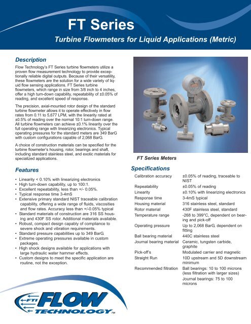
<strong>FT</strong> <strong>Series</strong><br />
<strong>Turbine</strong> <strong>Flow</strong>meters <strong>for</strong> <strong>Liquid</strong> <strong>Applications</strong> (Metric)<br />
Description<br />
<strong>Flow</strong> <strong>Technology</strong>’s <strong>FT</strong> <strong>Series</strong> turbine flowmeters utilize a<br />
proven flow measurement technology to provide exceptionally<br />
reliable digital outputs. Because of their versatility,<br />
these flowmeters are the solution <strong>for</strong> a wide variety of liquid<br />
flow sensing applications. <strong>FT</strong> <strong>Series</strong> turbine<br />
flowmeters, which range in size from 3/8 inch to 4 inches,<br />
offer a high turn-down capability, repeatability of ±0.05% of<br />
reading, and excellent speed of response.<br />
The precision, axial-mounted rotor design of the standard<br />
turbine flowmeter allows it to operate effectively in flow<br />
rates from 0.11 to 5,677 LPM, with the linearity rated at<br />
±0.5% of reading over the normal 10:1 turn-down range.<br />
All turbine flowmeters can achieve ±0.1% linearity over the<br />
full operating range with linearizing electronics. Typical<br />
operating pressures <strong>for</strong> the standard meters are 349 BarG<br />
with custom configurations capable of 2,068 BarG.<br />
A choice of construction materials can be specified <strong>for</strong> the<br />
turbine flowmeter’s housing, rotor, bearings and shaft,<br />
including standard stainless steel, and exotic materials <strong>for</strong><br />
specialized applications.<br />
Features<br />
• Linearity < 0.10% with linearizing electronics<br />
• High turn-down capability, up to 100:1.<br />
• Excellent repeatability, less than +/- 0.05%.<br />
• Typical response time 3-4mS<br />
• Extensive primary standard NIST traceable calibration<br />
capability, offering a wide range of fluids, viscosities<br />
and flow rates. Accuracy less than +/-0.05% typical<br />
• Standard materials of construction are 316 SS housing<br />
and 430F SS rotor. Additional materials available.<br />
• Robust, compact design capably of compliance to<br />
severe shock and vibration requirements.<br />
• Standard pressure capabilities up to 349 BarG.<br />
• Extreme operating pressures available in custom<br />
packages.<br />
• High shock designs available <strong>for</strong> applications with<br />
large hydraulic water hammer effects.<br />
• Custom designs to meet the specific application are<br />
routine, not the exception.<br />
<strong>FT</strong> <strong>Series</strong> Meters<br />
Specifications<br />
Calibration accuracy<br />
Repeatability<br />
Linearity<br />
Response time<br />
Housing material<br />
Rotor material<br />
Temperature range<br />
Operating pressure<br />
Ball bearing material<br />
Journal bearing material<br />
Pick-off’s<br />
Straight Run<br />
Recommended filtration<br />
±0.05% of reading, traceable to<br />
NIST<br />
±0.05% of reading<br />
±0.10% with linearizing electronics<br />
3-4mS typical<br />
316 stainless steel, standard<br />
430F stainless steel, standard<br />
-268 to 399°C, dependent on bearing<br />
and pick-off<br />
Up to 2,068 BarG, dependent on<br />
fitting<br />
440C stainless steel<br />
Ceramic, tungsten carbide,<br />
graphite<br />
Modulated carrier and magnetic<br />
10D upstream and 5D downstream<br />
minimum<br />
Ball bearings: 10 to 100 microns<br />
(less filtration with larger sizes)<br />
Journal bearings: 75 to 100<br />
microns
<strong>FT</strong> <strong>Series</strong><br />
<strong>Turbine</strong> <strong>Flow</strong> Meter Model Number<br />
Selection and Sizing Guidelines<br />
There are 4 major steps in defining a turbine flow meter;<br />
these are:<br />
• Choosing the flow meter size<br />
• Bearing selection<br />
• Pick-off selection<br />
• Calibration requirements<br />
These components are interrelated and should be considered<br />
as a system to obtain optimum meter per<strong>for</strong>mance.<br />
Additional options need to be selected that are related<br />
more to personal preference. These are end fitting type,<br />
materials of construction, and units of measure.<br />
Step 1: Meter size and flow range selection<br />
Detailed below are the considerations that should be<br />
taken into account when sizing a flow meter.<br />
• Due to the laws of physics, <strong>for</strong> optimum results any flow<br />
meter (including turbine flow meters) should be operated<br />
as high up in their turndown range as possible.<br />
• Clearly, there is a tradeoff between your allowable pressure<br />
drop and the size of meter that you can install into<br />
your process. In other words, at a given flow rate, a<br />
smaller meter will operate higher up in its flow rate<br />
range, but will generate a higher pressure drop.<br />
• When selecting the size and flow range of the meter,<br />
bearing and pick-off selection must be considered. Ball<br />
bearings and RF pick-offs have the least amount of drag,<br />
thus provide the widest capable flow range. Journal<br />
bearings and magnetic pick-offs create more drag, there<br />
<strong>for</strong>e reducing the turndown capability of the flow meter.<br />
Where ever possible an RF pickoff is the ideal choice.<br />
• Ideally, it is beneficial to stay within a 10:1 turndown<br />
range. However, the phenomenal repeatability and primary<br />
calibration accuracy’s enable the <strong>Flow</strong> <strong>Technology</strong><br />
turbine to provide outstanding per<strong>for</strong>mance over a 100:1<br />
turndown.<br />
• See page 4 <strong>for</strong> available flow ranges.<br />
Step 2: Pickoff Selection<br />
Reasons to choose a RF pickoff<br />
• Use on <strong>FT</strong>-24 and smaller meters.<br />
• Use when extended flow range is required.<br />
• Use when real time temperature correction (UVC calibration)<br />
is required.<br />
• <strong>Flow</strong> meter does not require recalibration when pick-off<br />
is changed.<br />
• Must be used in conjunction with an amplifier to produce<br />
a square wave frequency output.<br />
• Can not be used above an <strong>FT</strong>-40 size flow meter.<br />
Reasons to choose a Magnetic pickoff<br />
• Use on <strong>FT</strong>-32 and larger meters.<br />
• Use on cryogenic temperature applications.<br />
• Use when a direct millivolt output is required.<br />
• <strong>Flow</strong> meter should be recalibrated when pick-off is<br />
changed.<br />
• Can be used on smaller flow meters with reduced flow<br />
range.<br />
2<br />
Pick-off Options<br />
• Standard pick-offs have upper operating temperature of<br />
177˚C.<br />
• High temperature pick-offs with a 399˚C maximum are<br />
available.<br />
• Most electronics are available in hazardous area rated<br />
enclosures. If system certification is required, pick-offs<br />
are available with various ratings.<br />
• Pick-offs are available with built in RTD’s when real<br />
time temperature correction is required and a UVC calibration<br />
is per<strong>for</strong>med on the flow meter. These pick-offs<br />
are normally used in conjunction with the Linear Link<br />
TCI electronics.<br />
• Amplified pick-offs are available that house circuitry in<br />
the pick-off body to provide a high level 0 – 5 volt<br />
square wave pulse output. DC power is required.<br />
• See page 6 <strong>for</strong> pick-off selection options.<br />
MS connector<br />
Pick-off Mounting Configuration<br />
• Pick-offs have two, three or four pin MS connectors.<br />
• Connection to the pick-off is via a mating MS connector<br />
with soldered connections and loose wire.<br />
• Typical installation is on test stands or on board applications.<br />
• A junction box or conduit can not be attached to this<br />
pick-off style.<br />
• This pick-off is used on flow meters that do not have 1”<br />
MNPT nipples welded to the meter body surrounding<br />
the pick-off. <strong>Flow</strong> meters with threaded end connections<br />
typically do not have the 1” nipple.<br />
Flying leads with threaded connection<br />
• Pick-offs have flying leads extending from the potted<br />
pick-off body.<br />
• Mechanical connection to the pick-off is via a ½” MNPT<br />
thread integral to the top of the pick-off body or the 1”<br />
MNPT thread of the flow meter nipple.<br />
• This pick-of style is required when a junction box and<br />
rigid or flexible conduit is to be mounted directly to the<br />
pick-off body.<br />
• Typical installation is a more industrial environment.<br />
• This threaded body pick-off is used on flow meters that<br />
do not have 1” MNPT nipples welded to the meter body<br />
surrounding the pick-off. A flying lead pick-off with<br />
smooth body are used on flow meters that do have the<br />
1” MNPT nipple. <strong>Flow</strong> meters with threaded end connections<br />
typically do not have the 1” nipple. <strong>Flow</strong><br />
meters with flanged end connections typically do have<br />
the 1” nipple.
<strong>FT</strong> <strong>Series</strong><br />
Step 3: Bearing Selection<br />
Step 4: Calibration Selection<br />
• Bearings are available in two styles, Ball and Journal<br />
Sleeve.<br />
• Ball bearings are manufactured from 440C SS and is the<br />
typical choice <strong>for</strong> lubricating applications.<br />
• Journal Sleeve bearings are available in three different<br />
material selections. (Note: The Journal Ceramic bearing<br />
is the typical bearing of choice <strong>for</strong> non-lubricating appli<br />
cations.)<br />
• See page 5 <strong>for</strong> bearing selection options.<br />
Ball bearings (model # code “A”)<br />
• Bearing option to measure lubricating fluids.<br />
• Low frictional drag provides the widest possible flow<br />
range.<br />
• Ball bearing set can be replaced in the field.<br />
• 10 to 50 micron filtration required, dependent on meter<br />
size.<br />
• Operating temperature range of -266˚ to 149˚ C.<br />
• 440C stainless steel materials of construction.<br />
• Provides exceptional life and rugged construction in<br />
clean lubricating applications.<br />
Journal Carbide bearings (model # code “D”)<br />
• Bearing option to measure low or non-lubricating fluids.<br />
• Hard bearing material provides long life and rugged construction.<br />
• Less turn down capability than the ball bearing. (valid <strong>for</strong><br />
all journal bearing options)<br />
• Field replacement of bearing not recommended. (valid<br />
<strong>for</strong> all journal bearing options)<br />
• 75 to 100 micron filtration required. (valid <strong>for</strong> all journal<br />
bearing options)<br />
• Operating temperature range of -73˚ to 648˚ C.<br />
• Tungsten Carbide materials of construction.<br />
• Hard bearing material provides long life and rugged con<br />
struction.<br />
Journal Graphite bearings (model # code “E”)<br />
• Bearing option <strong>for</strong> corrosive applications.<br />
• Operating temperature range of -73˚ to 288˚ C.<br />
• Bearing option to measure low or non-lubricating fluids.<br />
• Materials of construction are epoxy impregnated Carbon<br />
Graphite bearing with 316 SS shaft.<br />
• Lubricating property of the graphite allows this bearing to<br />
run smoother than the other two journal options, however<br />
life of the bearing will be slightly reduced.<br />
• Not recommended <strong>for</strong> use above <strong>FT</strong>-32 meter size.<br />
• <strong>Flow</strong> <strong>Technology</strong> has one of the world’s largest liquid<br />
and gas primary calibration facilities.<br />
• The ability to accurately calibrate a flow meter with trace<br />
ability to international standards is one of the fundamental<br />
requirements in any flow metering application.<br />
• <strong>Flow</strong> <strong>Technology</strong> offers a range of water, solvent, oil, and<br />
oil blend calibrations.<br />
• A 10 data point calibration is offered as standard, 20 and<br />
30 point calibrations are offered as options. A higher<br />
number of data points will define the calibration curve in<br />
more detail. If linearizing electronics will be used a mini<br />
mum of a 20 point calibration is recommended.<br />
• Viscosity does shift the flow meter calibration curve and<br />
should be compensated <strong>for</strong>.<br />
Application will be at relatively constant temperature<br />
and viscosity<br />
• For optimum per<strong>for</strong>mance your flow meter should be calibrated<br />
close to its operating viscosity. Water at 1 cst and<br />
solvent at 1.2 cst viscosity is standard, a specific calibration<br />
to simulate the operating viscosity can be specified<br />
as an option.<br />
Application will cover a range of operating temperature<br />
and viscosity<br />
• If the fluid viscosity or density is changing due to temperature<br />
variation, a Universal Viscosity Calibration (UVC)<br />
should be used to per<strong>for</strong>m real time temperature correction.<br />
• The viscosity range <strong>for</strong> the calibration is determined by<br />
the minimum fluid viscosity at the maximum operating<br />
temperature and the maximum fluid viscosity at the minimum<br />
operating temperature.<br />
• See page 5 <strong>for</strong> calibration options.<br />
Journal Ceramic bearings (model # code “G”)<br />
• Typical bearing option to measure low or non-lubricating<br />
fluids.<br />
• Operating temperature range of -73˚ to 427˚ C.<br />
• Typical bearing option <strong>for</strong> more corrosive applications.<br />
• AL2O3 (99.5%) Ceramic materials of construction.<br />
• Ceramic material is impervious to most fluids, resists film<br />
build up on bearing surface, long life, not as robust as<br />
tungsten carbide material.<br />
• Not recommended <strong>for</strong> use in water above 82˚ C.<br />
3
<strong>FT</strong> <strong>Series</strong><br />
<strong>FT</strong> Meter Sizing and End Fittings<br />
Extended <strong>Flow</strong> Range<br />
<strong>Series</strong> /<br />
Order Code<br />
End Fitting<br />
Nominal<br />
Inches<br />
ID<br />
(mm)<br />
10:1 Standard Range<br />
Ball<br />
Bearing /<br />
RF Pickoff<br />
Ball<br />
Bearing<br />
Mag Pickoff<br />
Journal<br />
Bearing /<br />
RF Pickoff<br />
Journal<br />
Bearing /<br />
Mag Pickoff<br />
Max<br />
K Factor<br />
Maximum<br />
Frequency<br />
Approx.<br />
Min LPM Max LPM Min LPM Min LPM Min LPM Min LPM LPM P/L Frequ.<br />
<strong>FT</strong> 4-6 3/8 7.6 0.95 9.5 0.11 0.38 0.38 0.45 11 12680 2000<br />
<strong>FT</strong> 4-8 1/2 7.6 0.95 9.5 0.11 0.38 0.38 0.45 11 12680 2000<br />
<strong>FT</strong> 6-8 1/2 9.4 1.9 19 0.19 0.45 0.57 0.76 19 6600 2100<br />
<strong>FT</strong> 8-8 1/2 10 2.8 28 0.30 0.60 0.76 0.95 30 4200 2000<br />
<strong>FT</strong> -08 1/2 11 3.8 38 0.38 0.76 0.95 1.1 38 3170 2000<br />
<strong>FT</strong>-10 * 3/4 13 4.7 47 0.57 1.1 1.1 1.5 56 2540 2000<br />
<strong>FT</strong>-12 3/4 14 7.6 76 0.95 1.8 1.9 1.9 94 1580 2000<br />
<strong>FT</strong>-16 1 22 19 190 2.3 3.7 3.8 3.8 227 635 2000<br />
<strong>FT</strong>-20 11/4 25 34 340 3.8 5.6 3.8 5.7 378 345 1950<br />
<strong>FT</strong>-24 11/2 34 57 570 6.0 9.4 6.0 9.5 605 160 1500<br />
<strong>FT</strong>-32 2 44 85 850 9.5 13 9.5 13 946 92 1300<br />
<strong>FT</strong>-40 21/2 56 151 1510 17 19 17 19 1700 48 1200<br />
<strong>FT</strong>-48 3 73 246 2460 N/A 28 N/A 28 2838 20 812<br />
<strong>FT</strong>-64 4 98 473 4730 N/A 57 N/A 57 5677 8 625<br />
* AE fitting = 5/8”<br />
Order Code<br />
End Fittings<br />
AE<br />
NE<br />
HB<br />
WF<br />
C1<br />
C2<br />
C3<br />
C4<br />
C5<br />
C6<br />
D1<br />
D2<br />
D3<br />
D4<br />
D5<br />
D6<br />
AN (or MS) external straight threads - 3/8" to 2 1/2 nominal size - 37° flare<br />
NPT external threads - 1/2" to 4 nominal size<br />
Hose Barb - 13 to 51 mm<br />
Wafer type - serrated surface - 13 to 76 mm nominal size<br />
150# Raised Face Flange<br />
300# Raised Face Flange<br />
600# Raised Face Flange<br />
900# Raised Face Flange<br />
1500# Raised Face Flange<br />
2500# Raised Face Flange<br />
DIN Flange PN16<br />
DIN Flange PN40<br />
DIN Flange PN100<br />
DIN Flange PN160<br />
DIN Flange PN250<br />
DIN Flange PN400<br />
Part Number Structure<br />
F T x x x x x x x x L x x x x x x x<br />
Meter Size End Fittings Calibration Material Bearing Pickoff Optional Designators<br />
4
<strong>FT</strong> <strong>Series</strong><br />
Calibration<br />
Order Code # Points <strong>Flow</strong> Range Fluid<br />
Order Code # Points Cal Style # Viscosities<br />
NW 10 point normal 10:1 range in water<br />
NS 10 point normal 10:1 range in solvent<br />
NB 10 point normal 10:1 range in oil blend<br />
XW 10 point extended range in water<br />
XS 10 point extended range in solvent<br />
U2<br />
U3<br />
10 points each<br />
viscosity<br />
10 points each<br />
viscosity<br />
Universal<br />
Viscosity<br />
Curve<br />
Universal<br />
Viscosity<br />
Curve<br />
2 Viscosities (specify minimum<br />
viscosity & maximumviscosity).<br />
3 Viscosities (specify minimum<br />
viscosity & maximum viscosity).<br />
XB 10 point extended range in oil blend<br />
Order Code # Points # Pickoffs Cal Style Fluid<br />
TW 20 point normal 10:1 range in water<br />
TS 20 point normal 10:1 range in solvent<br />
BW<br />
10 points each<br />
direction<br />
1 pickoff Bi-directional water<br />
TB 20 point normal 10:1 range in oil blend<br />
YW 20 point extended range in water<br />
BS<br />
10 points each<br />
direction<br />
1 pickoff Bi-directional solvent<br />
YS 20 point extended range in solvent<br />
YB 20 point extended range in oil blend<br />
BB<br />
10 points each<br />
direction<br />
1 pickoff Bi-directional oil blend<br />
GW 30 point extended range in water<br />
GS 30 point extended range in solvent<br />
GB 30 point extended range in oil blend<br />
Note: W = Water. S = Solvent. B = Oil blend. The fluid viscosity must be provided<br />
with oil blend calibrations<br />
Material & Bearing Selection<br />
Order Code Housing Rotor Bearing Code<br />
E 316 SST 430F SST A - D - E - G - H<br />
3rd Digit of Calibration<br />
G 316 SST 316 SST D - E - G<br />
H 316 SST 17-4 PH SST A - D - E - G - H<br />
N HAST C HAST C E - G<br />
Code<br />
U<br />
R<br />
B<br />
The third digit of the calibration designator is<br />
normally not used and occupied by a dash (-).<br />
When required , the following codes are used.<br />
To signify required units of measure other than<br />
GPM<br />
To signify special calibration flow range other<br />
than normal 10:1 or extended range<br />
To signify both changes in units and special flow<br />
range.<br />
Note: Please contact factory <strong>for</strong> material codes “G”<br />
and “N”.<br />
Bearing Selection<br />
Order<br />
Code<br />
Bearing selections will affect flow range.<br />
Refer to sizing specification table to the left<br />
<strong>for</strong> correct flow ranges.<br />
A Ball Bearings (440 C)<br />
D<br />
E<br />
G<br />
Carbide Journal (Carbide Shaft & Sleeve)<br />
Graphite Journal (Graphite Sleeve, 316<br />
SST Shaft)<br />
Ceramic Journal (Ceramic Shaft & Sleeve)<br />
Part Number Structure<br />
F T x x x x x x x - L x x x x x x x<br />
Meter Size End Fittings Calibration Material Bearing Pickoff Optional Designators<br />
5
<strong>FT</strong> <strong>Series</strong><br />
Magnetic and RF Pickoff Selection Selection<br />
Order Code<br />
RF (Modulated Carrier)<br />
Order Code<br />
Magnetic<br />
-1 MS connector<br />
-5 Flying leads/threaded connection<br />
-L MS connector, 400° C max.<br />
-M Flying leads/threaded connection 400° C max.<br />
-8 MS connector, 330 µH coil<br />
-9 MS connector, 5/8"–18 thread, 1mH coil<br />
-Y CSA X-Proof<br />
T1<br />
T5<br />
RTD, MS connector<br />
RTD, flying leads/threaded connection<br />
-X I.S. approved, MS connector<br />
SS<br />
XX<br />
I.S. approved, flying leads/smooth body<br />
I.S. approved, flying leads/threaded body<br />
-2 MS connector<br />
-3 Flying leads/threaded connection<br />
-6 MS connector, 400° C max<br />
-7 Flying leads/threaded connection 400° C max.<br />
-Z CSA X-Proof<br />
T2<br />
T3<br />
RTD, MS connector<br />
RTD, flying leads/threaded connection<br />
-U I.S. approved, MS connector<br />
PP<br />
TT<br />
I.S. approved, flying leads/smooth body<br />
I.S. approved, flying leads/threaded body<br />
Notes: 1. Maximum temperature rating of pick-offs are 177˚ C unless<br />
otherwise noted.<br />
2. See Amplified Link literature <strong>for</strong> amplified pick-off codes.<br />
Part Number Structure<br />
F T x x x x x x x x L x x x x x x x<br />
Meter Size End Fittings Calibration Material Bearing Pickoff Optional Designators<br />
Dimensional Drawings<br />
MS / NPT Fitting<br />
Flange Fittings<br />
Hose Barb Fitting<br />
J<br />
N<br />
M<br />
<strong>Series</strong> A B<br />
mm mm<br />
<strong>FT</strong>4-6 62 25<br />
<strong>FT</strong>--8 62 25<br />
<strong>FT</strong>-10 69 35<br />
<strong>FT</strong>-12 83 35<br />
<strong>FT</strong>-16 90 41<br />
<strong>FT</strong>-20 103 48<br />
<strong>FT</strong>-24 117 57<br />
<strong>FT</strong>-32 154 70<br />
<strong>FT</strong>-40 226 89<br />
<strong>FT</strong>-48 N/A N/A<br />
<strong>FT</strong>-64 N/A N/A<br />
<strong>Series</strong> 150# 300# 600# 900#<br />
A<br />
mm<br />
B<br />
mm<br />
A<br />
mm<br />
B<br />
mm<br />
A<br />
mm<br />
B<br />
mm<br />
A<br />
mm<br />
B<br />
mm<br />
<strong>FT</strong>-_8 127 89 127 95 127 95 178 121<br />
<strong>FT</strong>-10 140 99 140 118 140 118 140 130<br />
<strong>FT</strong>-12 140 99 140 118 140 118 178 130<br />
<strong>FT</strong>-16 140 108 140 124 140 124 203 149<br />
<strong>FT</strong>-20 152 118 152 133 152 133 203 159<br />
<strong>FT</strong>-24 152 127 152 156 152 156 229 178<br />
<strong>FT</strong>-32 165 152 165 165 165 165 229 216<br />
<strong>FT</strong>-40 178 178 178 191 229 191 229 241<br />
<strong>FT</strong>-48 254 191 254 210 254 210 254 241<br />
<strong>FT</strong>-64 305 229 305 254 305 273 305 292<br />
Note: Contact factory <strong>for</strong> DIN dimensions<br />
<strong>Series</strong> J M N<br />
mm mm mm<br />
<strong>FT</strong>4-6 62.2 12.7 14.7<br />
<strong>FT</strong>--8 62.2 12.7 14.7<br />
<strong>FT</strong>-10 69.1 15.5 17.8<br />
<strong>FT</strong>-12 82.6 19.1 21.1<br />
<strong>FT</strong>-16 90.4 25.4 28.5<br />
<strong>FT</strong>-20 103.1 31.8 34.8<br />
<strong>FT</strong>-24 116.6 38.1 41.7<br />
<strong>FT</strong>-32 153.9 50.8 54.9<br />
<strong>FT</strong>-40 157.2 64.0 68.0<br />
<strong>FT</strong>-48 244.0 76.0 81.0<br />
<strong>FT</strong>-64 N/A N/A N/A<br />
8930 S. Beck Avenue, Suite 107, Tempe, Arizona 85284 USA<br />
Tel: (480) 240-3400 • Fax: (480) 240-3401 • Toll Free: 1-800-528-4225<br />
Trademarks are the property of their respective companies.<br />
E-mail: ftimarket@ftimeters.com • Web: www.ftimeters.com<br />
DB 68347 Rev C © 2007 <strong>FT</strong>I <strong>Flow</strong> <strong>Technology</strong>, Inc. Printed in USA