CATIA V5 Assembly Design
CATIA V5 Assembly Design
CATIA V5 Assembly Design

You also want an ePaper? Increase the reach of your titles
YUMPU automatically turns print PDFs into web optimized ePapers that Google loves.
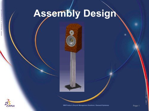
<strong>Assembly</strong> <strong>Design</strong><br />
IBM Product Lifecycle Management Solutions / Dassault Systemes<br />
Page 1<br />
© 1997 – 2001 DASSAULT SYSTEMES
Tutorial Objectives<br />
Description<br />
? This Tutorial is an introduction to <strong>Assembly</strong> <strong>Design</strong>.<br />
Message<br />
? <strong>Assembly</strong> <strong>Design</strong> is easy to use and powerful. The basics of product<br />
structure, constraints, and moving assemblies and parts can be learned<br />
quickly.<br />
? In this tutorial you will understand the power of associativity in <strong>CATIA</strong> <strong>V5</strong>,<br />
creating design in context and realising operations directly in the assembly<br />
design.<br />
? We will see the facility to use sub assemblies and constraints.<br />
Duration<br />
? 45 minutes<br />
Product Coverage<br />
? <strong>Assembly</strong> <strong>Design</strong>, Part <strong>Design</strong><br />
IBM Product Lifecycle Management Solutions / Dassault Systemes<br />
Page 2<br />
© 1997 – 2001 DASSAULT SYSTEMES
Here are the major steps of the tutorial:<br />
Step 1<br />
? Add a part into an assembly<br />
Step 2<br />
? Fix create constraints between this new part and other parts<br />
Step 3<br />
? When the tweeter is inserted, repeat this operation with the woofer<br />
Step 4<br />
? Create Holes in the Box to add screws<br />
Step 5<br />
? Add screws from a catalog<br />
Step 6<br />
? Modify the size of the Box and check the associativity<br />
Step 7<br />
? <strong>Assembly</strong> Feature<br />
Step 8<br />
? Manipulation with respect to the constraints<br />
Step 9<br />
? Exploded view<br />
Step 10<br />
? Hyperlinks<br />
IBM Product Lifecycle Management Solutions / Dassault Systemes<br />
Tutorial Major Steps<br />
Page 3<br />
© 1997 – 2001 DASSAULT SYSTEMES
Depending on your needs, you may have to modify the <strong>CATIA</strong> <strong>V5</strong> settings (units, default<br />
directory, visualisation parameters, etc…)<br />
In order to use the appropriate settings for this tutorial, you have two possibilities:<br />
1. Do the following operations (simplest one):<br />
?BEFORE STARTING YOUR <strong>CATIA</strong> <strong>V5</strong> SESSION:<br />
? Copy or replace the directory ..\<strong>Assembly</strong> <strong>Design</strong>\Data\CATSettings in:<br />
For NT users<br />
For Windows 2000<br />
or XP users<br />
For Windows<br />
98 users<br />
C:\Winnt\Profiles\XXXXX\Application Data\DassaultSystemes<br />
C:\Documents and settings\Profiles\XXXXX\Application Data\DassaultSystemes<br />
C:\Windows\Profiles\XXXXX\Application Data\DassaultSystemes<br />
XXXX is the name used to log on to your computer<br />
Settings<br />
? Do not forget to put this folder (CATSettings) in read mode:<br />
? Select the folder (CATSettings)<br />
? Click mouse button 3 then click on Properties and<br />
uncheck the Read-only Attribute<br />
? Select all the files in the folder<br />
? Click mouse button 3 then click on Properties and uncheck the Read-only<br />
Attribute<br />
2. Set them manually:<br />
? Launch your <strong>CATIA</strong> <strong>V5</strong> session and do the operations from page 50 onwards<br />
IBM Product Lifecycle Management Solutions / Dassault Systemes Page 4<br />
© 1997 – 2001 DASSAULT SYSTEMES
Settings 2/2<br />
For this tutorial you also need to install a material catalogue:<br />
? Do not do this step if you have already done it in getting started or in a previous tutorial<br />
? Copy the ..\Getting Started\Catalog.CATMaterial file under ..\Program<br />
Files\Dassault Systemes\M07\intel_a\startup\materials\French directory<br />
? Copy the ..\Getting Started\Catalog.CATMaterial file under ..\Program<br />
Files\Dassault Systemes\M07\intel_a\startup\materials\German directory<br />
? Copy the ..\Getting Started\Catalog.CATMaterial file under ..\Program<br />
Files\Dassault Systemes\M07\intel_a\startup\materials\Japanese directory<br />
? Copy the ..\Getting Started\Catalog.CATMaterial file under ..\Program<br />
Files\Dassault Systemes\M07\intel_a\startup\materials directory<br />
? Answer Yes in order to replace the old catalogue<br />
You are now ready to launch your <strong>CATIA</strong> <strong>V5</strong> session<br />
IBM Product Lifecycle Management Solutions / Dassault Systemes<br />
Page 5<br />
© 1997 – 2001 DASSAULT SYSTEMES
Start Scenario<br />
We will work on the product that appears when<br />
<strong>CATIA</strong> starts<br />
? <strong>CATIA</strong> starts in the Product Structure<br />
workbench with Product1 selected in the tree<br />
?Select Start + Mechanical <strong>Design</strong> +<br />
<strong>Assembly</strong> <strong>Design</strong> to access the assembly tools<br />
? Here we will change the name of the product<br />
?Click on the “Product1” name in the<br />
specification tree<br />
?Click MB3 + Properties to display the<br />
Properties dialogue box<br />
?Select Product tab<br />
?Double-Click in the Part Number field<br />
?Enter “Loudspeaker” instead of Product1<br />
?Click OK<br />
IBM Product Lifecycle Management Solutions / Dassault Systemes<br />
Page 6<br />
© 1997 – 2001 DASSAULT SYSTEMES
Step 1: Open the Box<br />
Opening an existing part<br />
? Opening Two_Way_Box.CATPart<br />
?File + Open in the Menu Bar<br />
? <strong>CATIA</strong> also supports Windows<br />
standard hotkeys such as +O<br />
for open and +N for new<br />
?Select Show Preview to preview a<br />
part or an assembly<br />
? You can preview your models<br />
before you open them. Notice the<br />
preview is very fast. This is because<br />
you are only reading the image in the<br />
NT metafile<br />
?Select Two_Way_Box.CATPart in<br />
the … \<strong>Assembly</strong> <strong>Design</strong> \Data\<br />
directory<br />
? The path will depend on where you<br />
installed the data<br />
?Click Open<br />
IBM Product Lifecycle Management Solutions / Dassault Systemes<br />
Page 7<br />
© 1997 – 2001 DASSAULT SYSTEMES
Step 1: Customise a Hotkey<br />
Customising a Hotkey<br />
? You could use the pulldown Window-Tile<br />
Vertically to do this action, but we would like you<br />
to take a moment to see how easy it is to create<br />
a Hotkey<br />
? Click MB3 on any icon and choose<br />
Customize from the contextual menu<br />
? You can also use Tools + Customize in<br />
the Menu bar<br />
? Select the Commands tab<br />
? Select Window on the left part of the<br />
window<br />
? Select Tile Vertically on the right part of<br />
the window<br />
? Click on Show Properties button<br />
? Enter F4 into Accelerator<br />
? Click Close<br />
? You can check the result of your customisation<br />
? Hit F4 to tile your windows vertically<br />
IBM Product Lifecycle Management Solutions / Dassault Systemes<br />
Page 8<br />
© 1997 – 2001 DASSAULT SYSTEMES
Step 1: Add first part to assembly<br />
Dragging and dropping the part into the product<br />
? You will insert the Part into the <strong>Assembly</strong><br />
? Select the side or front face of the Box and drag it<br />
onto the top of the tree in the assembly window<br />
(holding MB1)<br />
? You will see a ‘+’ on your cursor as shown<br />
? You could also have selected Two_Way_Box at the<br />
top of the part tree and dragged it onto Loudspeaker at<br />
the top of the <strong>Assembly</strong> tree<br />
? Now you will continue inserting and constraining further<br />
parts in the assembly window<br />
? Maximise the assembly window (Product.1)<br />
? Select Fit all in<br />
? Select Fix Component icon<br />
?If you don’t see the icon, it means that the<br />
corresponding toolbar is hidden due to your display<br />
settings. To find it, drag and drop the empty area from<br />
the bottom right side to the centre of the 3D view.<br />
Repeat this operation until you find the right toolbar. To<br />
put it back, do the reverse operation<br />
? Two_Way_Box.CATPart is already selected<br />
? Click on the ‘+’ sign of the Constraint line to display<br />
the constraints you have created<br />
IBM Product Lifecycle Management Solutions / Dassault Systemes<br />
Page 9<br />
© 1997 – 2001 DASSAULT SYSTEMES
Step 1: Use the Hide/Show mode<br />
? You will now see that you can use 2 layers in<br />
the 3D view: the Show view and the No Show<br />
view. The No Show view is used to store all the<br />
unneeded elements.<br />
? Select the Anchor in the 3D view or the<br />
Fix.1 (Two_Way_Box.1) line in the tree<br />
? Click on the Hide/Show icon on the<br />
bottom toolbar to hide the constraint<br />
visualisation<br />
? We will temporarily hide this constraint.<br />
Notice the constraint is now greyed out in the<br />
tree as well as hidden in the geometry view<br />
? Click on the Swap visible space icon<br />
? This displays the No Show layer<br />
? You should now see the constraint and the<br />
geometry used to create the box<br />
? Click Swap visible space again to go<br />
back to the Show view<br />
? Select Fit All In<br />
IBM Product Lifecycle Management Solutions / Dassault Systemes<br />
Page 10<br />
© 1997 – 2001 DASSAULT SYSTEMES
Step 2: Add the Tweeter to the <strong>Assembly</strong><br />
Adding the Tweeter to the Loudspeaker<br />
? Now you are in the right workbench, you<br />
can insert the tweeter<br />
?Click MB3 on Loudspeaker at the<br />
top of the tree or the Existing<br />
Component icon<br />
?In the contextual menu choose<br />
Components + Existing<br />
Component…<br />
?In the Insert an Existing<br />
Component window, Open<br />
…\<strong>Assembly</strong> <strong>Design</strong> \Data\<br />
tweeter\tweeter.CATProduct<br />
IBM Product Lifecycle Management Solutions / Dassault Systemes<br />
Page 11<br />
© 1997 – 2001 DASSAULT SYSTEMES
Step 2: Move tweeter in assembly<br />
Moving the Tweeter<br />
? You can roughly position a part using the<br />
Compass ( At the top right of the screen )<br />
? Place the mouse cursor on the red dot of<br />
the Compass<br />
? When the cursor becomes a cross, hold<br />
down MB1<br />
? Drag the Compass onto the front face of<br />
the tweeter sub-assembly then release MB1<br />
? The compass will turn bright green,<br />
indicating that it can be used to move the part<br />
? Place the mouse cursor on the vertical<br />
axis and when it turns orange, hold MB1<br />
and drag the tweeter outside the box<br />
? Using the other axis of the Compass,<br />
repeat the operation to position the tweeter<br />
as shown<br />
IBM Product Lifecycle Management Solutions / Dassault Systemes<br />
Page 12<br />
© 1997 – 2001 DASSAULT SYSTEMES
Step 2: Move tweeter in assembly<br />
Moving the Tweeter<br />
? You can also rotate a part…<br />
?Select here to rotate the tweeter<br />
~30° clockwise about the x axis<br />
?Drag the red dot compass away<br />
from the tweeter holding MB1 and<br />
shift<br />
? Shift resets the compass (z axis<br />
up)<br />
?Click MB3 on the face of the<br />
tweeter. Select Reframe On to zoom<br />
in on the tweeter<br />
?Click off the geometry to deselect<br />
the tweeter face<br />
IBM Product Lifecycle Management Solutions / Dassault Systemes<br />
Page 13<br />
© 1997 – 2001 DASSAULT SYSTEMES
Step 2: Add constraints<br />
Creating Coincidence Constraints<br />
? You’ll now fix some assembly constraints<br />
? Select Coincidence Constraint icon<br />
? Select these 2 cylindrical surfaces (both<br />
internal hole faces)<br />
? DO NOT HESITATE TO ZOOM on these<br />
faces to be sure you select them (please<br />
refer to the Get Started scenario to find out<br />
about zooming)<br />
? The tweeter will snap into place<br />
? Select these 2 cylindrical surfaces (both<br />
internal hole faces) while holding <br />
? Select Coincidence Constraint again<br />
? The tweeter will rotate into place<br />
? You have seen two ways for the creation<br />
of a constraint : icon – object / object - icon<br />
IBM Product Lifecycle Management Solutions / Dassault Systemes<br />
Page 14<br />
© 1997 – 2001 DASSAULT SYSTEMES
Step 2: Add Constraints<br />
Creating Contact Constraints<br />
? Now you have created some<br />
coincidence constraints, you will create a<br />
contact constraint to finish mounting the<br />
tweeter on the box<br />
?Click on the Contact Constraint<br />
icon<br />
?Select this face on the tweeter<br />
?Select this face on the box<br />
? The tweeter will snap into place<br />
IBM Product Lifecycle Management Solutions / Dassault Systemes<br />
Page 15<br />
© 1997 – 2001 DASSAULT SYSTEMES
Step 2: Hide Constraints<br />
Hiding constraints and planes<br />
? As before, you can make the view<br />
clearer by moving the new constraints<br />
onto the No Show layer<br />
?Holding the key Select<br />
Constraints from the tree and this<br />
plane from the geometry<br />
?Select Hide/Show icon<br />
IBM Product Lifecycle Management Solutions / Dassault Systemes<br />
Page 16<br />
© 1997 – 2001 DASSAULT SYSTEMES
Step 2: <strong>Assembly</strong> level associativity<br />
Modification of one part<br />
? You will now use both views: The <strong>Assembly</strong><br />
context view and the Part context view. You need<br />
to modify the dimension between the two holes<br />
because they are too close<br />
? Windows + Tile Vertically in the menu<br />
bar or Hit F4 key if you already have gone<br />
through the Part <strong>Design</strong> scenario where you<br />
learn how to create a Hotkey<br />
? In the Part window (Two_way_box<br />
.CATPart ) double-click the internal face of<br />
the tweeter hole<br />
? Double-click the 223 dimension value<br />
? Move the definition panel to see the 223<br />
dimension value.<br />
? Modify it from 223mm to 240mm and<br />
press <br />
? Select OK in Hole Definition dialog box<br />
? Click inside the assembly window<br />
? “Notice the tweeter automatically moves to<br />
fit the hole. This is an example of <strong>Assembly</strong><br />
level associativity.<br />
? Maximise the assembly window<br />
? Zoom out or Fit All In to show the entire<br />
speaker<br />
IBM Product Lifecycle Management Solutions / Dassault Systemes<br />
Page 17<br />
© 1997 – 2001 DASSAULT SYSTEMES
Step 3: Add Woofer to assembly<br />
Adding the Woofer to the Loudspeaker<br />
? Now you will repeat the operation for the<br />
Woofer<br />
? Click MB3 on Loudspeaker at the top of<br />
the tree<br />
? Click the Existing Component icon<br />
? Preview the parts that make up the woofer<br />
? Select … \<strong>Assembly</strong> <strong>Design</strong>\<br />
Data\250mm Driver.CATProduct<br />
? Click Open<br />
Moving the woofer<br />
? Drag the compass onto the Diaphragm of the<br />
woofer<br />
? The compass should be as shown<br />
? Click MB3 on the compass and choose<br />
Edit<br />
? Type in 350<br />
? The x direction is already selected.<br />
? Click Apply new position<br />
? Select Close in Compass Manipulation<br />
dialog box<br />
? Drag the compass away from the woofer<br />
? Click anywhere in the background to deselect<br />
the geometries<br />
IBM Product Lifecycle Management Solutions / Dassault Systemes<br />
Page 18<br />
© 1997 – 2001 DASSAULT SYSTEMES
Step 3: Constrain woofer<br />
Creating Coincidence Constraint<br />
? Adding a coincidence constraint<br />
?Select Coincidence Constraint<br />
icon<br />
?Click MB1 to select this cylindrical<br />
surface on the Diaphragm<br />
?Click MB1 to select this cylindrical<br />
surface on the box<br />
Creating Contact Constraint<br />
? Adding a Contact constraint<br />
?Select Contact Constraint icon<br />
?Select this face on the woofer<br />
? If the orientation of the view is not<br />
as shown, you can rotate the view<br />
?Select this face on the box<br />
? The woofer should snap into place<br />
IBM Product Lifecycle Management Solutions / Dassault Systemes<br />
Page 19<br />
© 1997 – 2001 DASSAULT SYSTEMES
Step 3: Parallelism Constraint<br />
Creating Parallelism Constraint<br />
? To show you some other possibilities,<br />
we will create a parallelism constraint to<br />
orientate the Woofer into the Box<br />
?Select Angle Constraint icon<br />
?Select the plane from the box<br />
?Select the plane from the woofer<br />
?In the Constraint Properties<br />
window, check Parallelism<br />
? If this were not a symmetrical part<br />
you could select the green arrow to<br />
rotate it<br />
?Click OK<br />
IBM Product Lifecycle Management Solutions / Dassault Systemes<br />
Page 20<br />
© 1997 – 2001 DASSAULT SYSTEMES
Step 3: Hide constraints and planes<br />
Hiding constraints and planes<br />
? You can now Hide the new constraints<br />
?Holding ( on the key<br />
board ) select the plane on the woofer<br />
and the 3 constraints at the bottom of<br />
the tree<br />
?Click MB3 and select Hide/Show<br />
?Hit F3 to hide the tree<br />
?Double-click the box in the<br />
geometry view<br />
? This will bring us into the part<br />
<strong>Design</strong> workbench.<br />
? We are now editing the box in the<br />
the assembly view<br />
? Click MB2 on the hole to re-centre on it<br />
?Zoom in on this hole<br />
IBM Product Lifecycle Management Solutions / Dassault Systemes<br />
Page 21<br />
© 1997 – 2001 DASSAULT SYSTEMES
Step 4: Part <strong>Design</strong> in the assembly view<br />
Making a hole in the box<br />
? Use the assembly view to create the corresponding<br />
holes in the Box part<br />
? Select this edge<br />
? Hold and select this surface<br />
? We are going to put a hole in the box that will stay<br />
concentric to this hole in the woofer<br />
? Select Hole icon<br />
? Answer Yes to the question if it appears<br />
? The link between the hole of the Box and the circle of<br />
the Woofer hole will remain. Any modification made to the<br />
hole in the box will also be applied to the hole in the<br />
woofer<br />
? Select Up To Next<br />
? Selecting Up To Next means that if we modify the<br />
thickness of box, the hole will be adjusted accordingly<br />
? Enter 4mm in the Diameter field<br />
? Select Positioning Sketch to check the<br />
concentricity<br />
?You can see that a coincidence constraint has been<br />
automatically created<br />
? Select Exit Workbench icon to exit the sketcher<br />
? Click OK to close the Hole Definition window<br />
IBM Product Lifecycle Management Solutions / Dassault Systemes<br />
Page 22<br />
© 1997 – 2001 DASSAULT SYSTEMES
Step 4: Part <strong>Design</strong> in the assembly view<br />
Patterning the hole<br />
? You will now create a series of holes around the woofer<br />
axis<br />
? Click and hold MB1 on the black arrow at the<br />
bottom right of the Rectangular Pattern icon<br />
? Drag the mouse then release MB1 on the Circular<br />
Pattern icon<br />
? Select Complete Crown in the Parameters field<br />
? Click MB3 on Instance(s) field and select Edit<br />
Formula<br />
? Select one of the 3 other holes on the woofer (not<br />
where the hole is apply ).<br />
? You will need to pan down<br />
? Select Number of Holes<br />
? External parameter selection dialogue box<br />
? Select OK to close External Parameter selection<br />
window<br />
? Select OK to close Formula Editor window<br />
? Select the Reference element field<br />
? Select the cylindrical surface of the box shown as<br />
the reference element<br />
? You may have to zoom in on this area to select the right<br />
face<br />
? Select YES<br />
? Select OK<br />
? The hole pattern on the box is driven by the hole pattern on<br />
the woofer<br />
IBM Product Lifecycle Management Solutions / Dassault Systemes<br />
Page 23<br />
© 1997 – 2001 DASSAULT SYSTEMES
Step 4: <strong>Assembly</strong> Level associativity<br />
Illustrating assembly level associativity<br />
? As the number of holes are linked, any<br />
modification of the number of Woofer holes will<br />
have the same result for the Box ones<br />
? Double click the hole in the woofer<br />
?The hole you are already zoomed in on<br />
? This brings us into Part design for the<br />
woofer<br />
? Double click again on it to edit the<br />
definition of the circular pattern<br />
? Zoom out to see the holes<br />
? Change Instances from 4 to 6<br />
?Use the up arrow or enter the value<br />
? Select OK<br />
? Notice the box has turned bright red<br />
indicating the hole pattern should be updated<br />
to match the pattern in the woofer<br />
? Hit F3 to show the tree<br />
? Double click Loudspeaker at the top of<br />
the tree<br />
? the links are automatically updated and<br />
you enter the <strong>Assembly</strong> <strong>Design</strong> workbench<br />
? Zoom in to add the first screw to the hole<br />
as shown<br />
? Next we will add screws to the assembly<br />
using a standard parts catalog<br />
IBM Product Lifecycle Management Solutions / Dassault Systemes<br />
Page 24<br />
© 1997 – 2001 DASSAULT SYSTEMES
Step 5: Insert screw from catalog<br />
Inserting screw from catalog<br />
? You will now insert some screws into the<br />
series of holes<br />
? Select the Catalog Browser icon<br />
? Remember to put the bottom toolbar out to<br />
find the missing icons…<br />
? Select Browse another catalog button<br />
? Find and Double-click … \<strong>Assembly</strong><br />
<strong>Design</strong>\Data\ISO_4762.catalog<br />
? You don’t have access to the Standard<br />
Part catalog because you are in a<br />
Demonstration Mode. If you want to use<br />
the Full provided Catalog, do not hesitate<br />
to contact your Business Partner<br />
? Drag and drop ISO 4762 screw M5x20…<br />
into Loudspeaker at the top of the tree<br />
? You see the screw in the tree but not in<br />
the 3D view. This is normal… In fact, the<br />
screw is inside the Loudspeaker… In the<br />
next step, we will move it.<br />
? Close the Catalog<br />
IBM Product Lifecycle Management Solutions / Dassault Systemes<br />
Page 25<br />
© 1997 – 2001 DASSAULT SYSTEMES
Step 5: <strong>Assembly</strong> Constraints<br />
Moving the screw<br />
? Position the screw to create the<br />
constraints<br />
?Drag the compass onto the front of<br />
the speaker<br />
?Select Screw from tree<br />
?If not already selected<br />
?Dragging the compass, select<br />
either a green axis or a blue plane<br />
and move the screw to its<br />
approximate position<br />
?When you are satisfied with the<br />
position of the screw, drag the red dot<br />
of the compass away from the<br />
tweeter holding MB1 + shift<br />
? Shift resets the compass (z axis<br />
up)<br />
IBM Product Lifecycle Management Solutions / Dassault Systemes<br />
Page 26<br />
© 1997 – 2001 DASSAULT SYSTEMES
Step 5: <strong>Assembly</strong> Constraints<br />
Constraining the Screw<br />
? Create a Coincidence constraint between the<br />
screw and the hole axis<br />
?Select the Coincidence Constraint icon<br />
?Select the cylindrical surface of the screw<br />
?Select the internal cylindrical surface on<br />
woofer<br />
? The screw snaps into place<br />
?Select the Contact Constraint icon<br />
?Select the flat face on the woofer hole<br />
?Select the flat face on the screw<br />
? Don’t hesitate to rotate the assembly using<br />
MB2 + MB1 (see Get Started exercises) then<br />
select the back face of the screw<br />
IBM Product Lifecycle Management Solutions / Dassault Systemes<br />
Page 27<br />
© 1997 – 2001 DASSAULT SYSTEMES
Step 5: Align screws with reference pattern<br />
Aligning the screws with the reference<br />
pattern<br />
? Here you will reuse the existing pattern to<br />
create as many screws as you have holes<br />
? Select the screw in 3D Geometry View<br />
? Select Reuse Pattern icon<br />
? Select here<br />
? Select this hole on the woofer<br />
? Check All under Re-use Constraints<br />
? Select OK<br />
? We now have 6 screws with their<br />
constraints. You cam reduce the Constraints<br />
tree by clicking on the (-) sign<br />
Creating another series of screws<br />
? Duplicate the screw using an existing one<br />
? Hit F3 to show the tree<br />
? Drag the last screw into Loudspeaker in<br />
the tree holding key<br />
? You should see a “+” sign<br />
? This will create another series of screws<br />
? Move the compass onto the face of the<br />
box<br />
? Select the last screw in the tree<br />
? Hit F3 to hide the tree<br />
? Drag the compass to move the screw<br />
near the tweeter<br />
IBM Product Lifecycle Management Solutions / Dassault Systemes<br />
Page 28<br />
© 1997 – 2001 DASSAULT SYSTEMES
Step 5: Screw in the Tweeter<br />
Constraining the screw<br />
? Creating the constraints<br />
?Select Coincidence Constraint<br />
icon<br />
?Select the cylindrical surface on the<br />
screw<br />
?Select the cylindrical surface on the<br />
tweeter<br />
?This time we are using the top left<br />
hole, which is #4 in the pattern<br />
? The screw snaps into place<br />
?Select Offset Constraint icon<br />
?Select the flat surface on the<br />
tweeter<br />
?Select the flat surface on the far<br />
side of the screw<br />
?Rotate the view if necessary<br />
?Set Orientation to Opposite<br />
?Set Offset to 0<br />
?Click OK<br />
IBM Product Lifecycle Management Solutions / Dassault Systemes<br />
Page 29<br />
© 1997 – 2001 DASSAULT SYSTEMES
Step 5: Align screws with reference pattern<br />
Aligning the screws<br />
? Creating and positioning the 3 other screws<br />
? The coincidence constraint is already<br />
selected<br />
? Select Reuse Pattern icon<br />
? Select All under Re-use Constraints<br />
? Click OK<br />
? We now have 10 screws with their<br />
constraints<br />
? This time we did not have to select the<br />
pattern, as the hole in the tweeter is already a<br />
member of the pattern<br />
? Hiding all the constraints<br />
? In the tree, select all the constraints you<br />
have just created and the three planes. Use<br />
the key (for multi selection) and<br />
click on the Hide/Show icon<br />
? The speaker is now complete. Let’s see<br />
what it looks like with another box<br />
configuration<br />
IBM Product Lifecycle Management Solutions / Dassault Systemes<br />
Page 30<br />
© 1997 – 2001 DASSAULT SYSTEMES
Step 6: <strong>Design</strong> Table<br />
<strong>Design</strong>ing Table<br />
? Modify the height of the Box<br />
? Double-click the side of the box<br />
? This brings us into Part <strong>Design</strong><br />
? Double-click on Configuration in the<br />
tree<br />
? Select this button in the window<br />
? Double click on line 2<br />
? Click OK<br />
? The assembly needs to be updated<br />
? Double-click on Loudspeaker at the top<br />
of the tree<br />
? This will update the locations of the<br />
woofer, tweeter and the screws<br />
? Hit F3 to hide the tree<br />
? Play a MP3 on your PC<br />
? Select View + Full Screen<br />
? Click MB3, then select Full Screen again<br />
to exit the Full Screen view<br />
IBM Product Lifecycle Management Solutions / Dassault Systemes<br />
Page 31<br />
© 1997 – 2001 DASSAULT SYSTEMES
Step 6: <strong>Design</strong> Table<br />
<strong>Design</strong>ing Table<br />
? Return to the first size:<br />
? Double-click the side of the box<br />
? This brings us into Part <strong>Design</strong><br />
? Double-click on Configuration in the<br />
tree<br />
? Select this button in the window<br />
? Double click on line 1<br />
? Click OK<br />
? The assembly needs to be updated<br />
? Double-click on Loudspeaker at the top<br />
of the tree<br />
? This will update the locations of the<br />
woofer, tweeter and the screws<br />
? Hit F3 to hide the tree<br />
? Play a MP3 on your PC<br />
? Select View + Full Screen<br />
? Click MB3, then select Full Screen again<br />
to exit the Full Screen view<br />
IBM Product Lifecycle Management Solutions / Dassault Systemes<br />
Page 32<br />
© 1997 – 2001 DASSAULT SYSTEMES
Step 6: Facultative point<br />
Facultative point:<br />
? If you had not enough time or if you had<br />
failed the steps before, you can load the<br />
following file:<br />
?Close all the windows present in<br />
<strong>CATIA</strong> <strong>V5</strong><br />
?Select file open<br />
? Find Loudspeaker product<br />
?Click Open or double click on<br />
Loudspeaker.CATProduct in<br />
../<strong>Assembly</strong> <strong>Design</strong>/Data/Step 7.<br />
? You are now able to continue the<br />
script.<br />
End of the facultative point<br />
IBM Product Lifecycle Management Solutions / Dassault Systemes<br />
Page 33<br />
© 1997 – 2001 DASSAULT SYSTEMES
Step 7: <strong>Assembly</strong> Feature<br />
Insert a support<br />
? Import the support:<br />
?Re-size the view<br />
?Double-click on Loudspeaker at<br />
the top of the tree<br />
? It will be highlighted in orange<br />
?Use the contextual menu on the<br />
Loudspeaker to insert a component.<br />
? MB 3 on Loudspeaker, and then<br />
Component/Existing Component<br />
?Select the Support.CATProduct<br />
In …\<strong>Assembly</strong> <strong>Design</strong>\Data\<br />
? You can focus your research on<br />
CATProducts, using “Files of type” :<br />
Products(*.CATProduct)<br />
?Click OK<br />
? The support is on the speaker.<br />
IBM Product Lifecycle Management Solutions / Dassault Systemes<br />
Page 34<br />
© 1997 – 2001 DASSAULT SYSTEMES
Step 7: <strong>Assembly</strong> Feature<br />
? Delete the fix constraint on the box<br />
?Click on the constraint in the tree<br />
? It will be highlighted in orange<br />
?Press the key < Delete > on your<br />
keyboard.<br />
IBM Product Lifecycle Management Solutions / Dassault Systemes<br />
Page 35<br />
© 1997 – 2001 DASSAULT SYSTEMES
Step 7: <strong>Assembly</strong> Feature<br />
Positioning<br />
? Move the imported product:<br />
?Re-size the view<br />
?Drag and drop the compass on the<br />
support in the 3D view<br />
? Place the compass on the 3D<br />
geometry.<br />
?Click on support in the tree to<br />
highlight it<br />
? The support can be now moved<br />
entirely.<br />
?Select the z axis on the compass<br />
to move down the support<br />
? Drag and drop the compass until<br />
it’s in the right place.<br />
?With a drag and drop, replace the<br />
compass on the bottom right axis.<br />
IBM Product Lifecycle Management Solutions / Dassault Systemes<br />
Page 36<br />
© 1997 – 2001 DASSAULT SYSTEMES
Step 7: <strong>Assembly</strong> Feature<br />
? Create automatically the coincidence<br />
constraints:<br />
?Re-size the view<br />
?Click on the Quick Constraint icon<br />
? This is a smart tool, which will<br />
recognise automatically the type of<br />
constraint regarding the type of<br />
geometry chosen.<br />
?Click the constraints:<br />
? You must zoom on the holes, as in<br />
the picture. When you approach the<br />
cylinder, <strong>CATIA</strong> will automatically<br />
detect the axis<br />
?Click on the two holes, as in<br />
picture 1<br />
?Click again on the Quick<br />
Constraint Icon<br />
?Click on the two holes, as in<br />
picture 2<br />
IBM Product Lifecycle Management Solutions / Dassault Systemes<br />
1<br />
2<br />
Page 37<br />
© 1997 – 2001 DASSAULT SYSTEMES
Step 7: <strong>Assembly</strong> Feature<br />
? Create automatically the contact<br />
constraints:<br />
?Click on the Quick Constraints<br />
?Click on the first face, as in the<br />
picture.<br />
? You must move the geometry to<br />
have a good view.<br />
?Stay at the “3D view” and approach<br />
the cursor on the second face, use<br />
the up arrow on the keyboard once,<br />
and then approach the cursor on the<br />
centre of the arrows. A circle will<br />
appear, click on it to accept the<br />
selection.<br />
? You can turn the assembly around<br />
1<br />
and select the face directly.<br />
IBM Product Lifecycle Management Solutions / Dassault Systemes<br />
2<br />
Page 38<br />
© 1997 – 2001 DASSAULT SYSTEMES
Step 7: <strong>Assembly</strong> Feature<br />
Split<br />
? Select the cutting element:<br />
?Open the tree, as in the picture<br />
?Click on the Split icon and select<br />
the join in the open body of Rotator<br />
Axis<br />
? This join will be the cutting<br />
element<br />
IBM Product Lifecycle Management Solutions / Dassault Systemes<br />
Page 39<br />
© 1997 – 2001 DASSAULT SYSTEMES
Step 7: <strong>Assembly</strong> Feature<br />
? Impact the Box :<br />
?Select the Two_Way_Box in the<br />
top panel.<br />
?Use the arrow to confirm your<br />
choice<br />
? The single arrow not the double<br />
?Change the direction by clicking on<br />
an orange arrow<br />
? As in the pictures<br />
?OK in the split Definition<br />
? If the panel Split Definition is not available<br />
move the Panel <strong>Assembly</strong> Feature Definition<br />
using a drag and drop on the top blue bar.<br />
IBM Product Lifecycle Management Solutions / Dassault Systemes<br />
Page 40<br />
© 1997 – 2001 DASSAULT SYSTEMES
Step 7: <strong>Assembly</strong> Feature<br />
See the result<br />
? Hide / Show the support to see the<br />
result:<br />
?Click on Support in the tree and<br />
then click on the Hide / Show icon<br />
? We see the impact of the split on<br />
the Two Way Box<br />
?Do the same<br />
? We have the entire <strong>Assembly</strong> now.<br />
?In the tree, select the<br />
Two_way_box, then with the<br />
contextual menu on it ( MB 3 ), select<br />
Components/Isolate Part.<br />
? You can isolate the parts from the<br />
links we created before at any time.<br />
IBM Product Lifecycle Management Solutions / Dassault Systemes<br />
Page 41<br />
© 1997 – 2001 DASSAULT SYSTEMES
Step 8: Manipulation with respect to the contraints<br />
Manipulation<br />
? Flexible Sub-<strong>Assembly</strong>:<br />
?Change the sub-product Support<br />
as a Flexible Sub-product, MB3 on<br />
Loudspeaker support in the tree, and<br />
click on Flexible/Rigid<br />
? We are now able to use the<br />
constraints inside the sub-product<br />
starting from the global product.<br />
? Also note that the icon in the tree<br />
has changed for another one in<br />
purple.<br />
?Select the manipulation Icon<br />
?Switch the button :<br />
With respect to constraints<br />
?Select the icon axis rotation.<br />
?And then select the axis as the<br />
picture by clicking on it.<br />
?Zoom back<br />
IBM Product Lifecycle Management Solutions / Dassault Systemes<br />
Page 42<br />
© 1997 – 2001 DASSAULT SYSTEMES
Step 8: Manipulation with respect to the contraints<br />
?Catch the two_way_box and turn it<br />
? You will perform a drag and drop,<br />
but without the drop.<br />
? When you find a position, just drop<br />
the cursor.<br />
?The manipulation is finished<br />
IBM Product Lifecycle Management Solutions / Dassault Systemes<br />
Page 43<br />
© 1997 – 2001 DASSAULT SYSTEMES
Step 9: Exploded View<br />
?We will create a scene where an<br />
exploded view will be realised. So<br />
click on this Icon<br />
?Select the name of your scene<br />
? Exploded view<br />
?Click OK twice.<br />
? You are now in the scene area,<br />
which has a green background<br />
?Select the exploded icon<br />
?Click on Loudspeaker in the tree<br />
? De-select the entire product<br />
?Select all the following designs by<br />
clicking on them in the tree:<br />
? You will obtain the following panel<br />
IBM Product Lifecycle Management Solutions / Dassault Systemes<br />
Page 44<br />
© 1997 – 2001 DASSAULT SYSTEMES
Step 9: Exploded View<br />
?Select the fixed product table<br />
? It will be highlighted in blue<br />
?Select the Two_Way_box in the<br />
tree<br />
?Change the Depth Definition for<br />
First level<br />
? The sub assembly will move as a<br />
whole - not as parts.<br />
?Click on Apply<br />
?Click on the left arrow to return to<br />
the previous step.<br />
?Click on the right arrow to chose<br />
the final exploded view and then click<br />
OK<br />
IBM Product Lifecycle Management Solutions / Dassault Systemes<br />
Page 45<br />
© 1997 – 2001 DASSAULT SYSTEMES
Step 9: Exploded View<br />
?Leave the scene by clicking on the<br />
exit Icon:<br />
? We are now in <strong>Assembly</strong> <strong>Design</strong><br />
?We can now return at anytime to<br />
the exploded view by double clicking<br />
on the small view at the bottom left of<br />
the <strong>CATIA</strong> window.<br />
? The exit will be like before<br />
IBM Product Lifecycle Management Solutions / Dassault Systemes<br />
Page 46<br />
© 1997 – 2001 DASSAULT SYSTEMES
Step 10: Hyperlinks<br />
? Re-size the view<br />
? Select the Flag Note Icon<br />
? This item creates hyperlinks between<br />
<strong>CATIA</strong> and other Files<br />
? Select the top of the box<br />
? Change the Name of the Hyperlink<br />
? Change to “Hyperlink”<br />
? Click on the Browse… Button and open<br />
the following files :<br />
250mmPlan.pdf<br />
Characteristic.pdf<br />
In …\<strong>Assembly</strong> <strong>Design</strong>\Data\<br />
? You can now switch the Go to button to<br />
activate the link and open the file.<br />
? Click on a line in the panel to activate<br />
the Go to button, and then click to active<br />
the link.<br />
IBM Product Lifecycle Management Solutions / Dassault Systemes<br />
Page 47<br />
© 1997 – 2001 DASSAULT SYSTEMES
Step 10: Hyperlinks<br />
?Click OK in the panel<br />
?MB3 on the Flag in the 3D view<br />
?Select the properties<br />
IBM Product Lifecycle Management Solutions / Dassault Systemes<br />
Page 48<br />
© 1997 – 2001 DASSAULT SYSTEMES
Manual Settings<br />
IBM Product Lifecycle Management Solutions / Dassault Systemes<br />
Page 49<br />
© 1997 – 2001 DASSAULT SYSTEMES
Settings<br />
Tools/Options<br />
? We will configure the environment of<br />
<strong>CATIA</strong><br />
?Select Tools + Options menu<br />
? We will erase any previous<br />
configurations.<br />
?Click on General<br />
?Click on the Reset Bottom<br />
?Select for all the tabpages<br />
?Click YES<br />
IBM Product Lifecycle Management Solutions / Dassault Systemes<br />
Page 50<br />
© 1997 – 2001 DASSAULT SYSTEMES
Settings<br />
Tools/Options<br />
? Under General select Parameters on<br />
the tree<br />
?Select to check With value and<br />
With formula<br />
? Under Infrastructure select Product<br />
Structure on the tree<br />
?Select to check :<br />
Automatic Expand<br />
Parameters<br />
Relations<br />
Products<br />
IBM Product Lifecycle Management Solutions / Dassault Systemes<br />
Page 51<br />
© 1997 – 2001 DASSAULT SYSTEMES
Settings<br />
Tools/Options<br />
? Under Mechanical <strong>Design</strong> select Part<br />
<strong>Design</strong> on the tree<br />
?Select the General folder<br />
?Select Keep link with selected<br />
object<br />
?Select Confirm when creating a<br />
link …<br />
?Select the Display folder<br />
?Select Constraints, Parameters,<br />
Relations<br />
? That’s all for the configuration<br />
?Select OK at the bottom right<br />
IBM Product Lifecycle Management Solutions / Dassault Systemes<br />
Page 52<br />
© 1997 – 2001 DASSAULT SYSTEMES
CONGRATULATIONS<br />
IBM Product Lifecycle Management Solutions / Dassault Systemes<br />
Page 53<br />
© 1997 – 2001 DASSAULT SYSTEMES