Hydraulic Accessories Index - Stauff
Hydraulic Accessories Index - Stauff
Hydraulic Accessories Index - Stauff

You also want an ePaper? Increase the reach of your titles
YUMPU automatically turns print PDFs into web optimized ePapers that Google loves.
<strong>Hydraulic</strong> <strong>Accessories</strong> <strong>Index</strong><br />
SUCTION STRAINERS<br />
• SUS Series - Aluminum End Cap . . . . . . . . . . . . . . . . . . . . . . . . . . . . . . . . . . . . . . .A2<br />
• SUS Series - Plastic End Cap . . . . . . . . . . . . . . . . . . . . . . . . . . . . . . . . . . . . . . . . . .A3<br />
• TMF Series - NPT Tank Mounted . . . . . . . . . . . . . . . . . . . . . . . . . . . . . . . . . . . . . . .A4<br />
• TMF Series - SAE O-Ring Tank Mounted . . . . . . . . . . . . . . . . . . . . . . . . . . . . . . . . .A5<br />
• TMF-HB Series Hose Barb Tank Mounted . . . . . . . . . . . . . . . . . . . . . . . . . . . . . . .A6<br />
• SAE O-Ring Weld Flanges WC Series . . . . . . . . . . . . . . . . . . . . . . . . . . . . . . . . . . .A7<br />
DIFFUSERS<br />
• SRV Series . . . . . . . . . . . . . . . . . . . . . . . . . . . . . . . . . . . . . . . . . . . . . . . . . . . . . . . . .A8<br />
FILLER BREATHERS<br />
• Metal SMBB/SMBT/SMBP . . . . . . . . . . . . . . . . . . . . . . . . . . . . . . . . . . . . . . . . .A9-12<br />
• Filler Breather Options . . . . . . . . . . . . . . . . . . . . . . . . . . . . . . . . . . . . . . . . . . . . . .A13<br />
• Metal Lockable SMBL . . . . . . . . . . . . . . . . . . . . . . . . . . . . . . . . . . . . . . . . . . . . . . .A14<br />
• Plastic SPB . . . . . . . . . . . . . . . . . . . . . . . . . . . . . . . . . . . . . . . . . . . . . . . . . . . .A15-17<br />
• Plastic SES . . . . . . . . . . . . . . . . . . . . . . . . . . . . . . . . . . . . . . . . . . . . . . . . . . . . . . .A18<br />
• Giant Air Breathers - SGB . . . . . . . . . . . . . . . . . . . . . . . . . . . . . . . . . . . . . . . . .A19-20<br />
DESICCANT BREATHERS<br />
• SDB/SVDB . . . . . . . . . . . . . . . . . . . . . . . . . . . . . . . . . . . . . . . . . . . . . . . . . . . . .A21-22<br />
FILLER BREATHER ADAPTORS<br />
• TBA Series . . . . . . . . . . . . . . . . . . . . . . . . . . . . . . . . . . . . . . . . . . . . . . . . . . . . . . . .A23<br />
• BA-6 . . . . . . . . . . . . . . . . . . . . . . . . . . . . . . . . . . . . . . . . . . . . . . . . . . . . . . . . . . . . .A24<br />
• BA-1/BA-2/BA-3/DBA-75 . . . . . . . . . . . . . . . . . . . . . . . . . . . . . . . . . . . . . . . . . . . .A25<br />
• Threaded Adaptors . . . . . . . . . . . . . . . . . . . . . . . . . . . . . . . . . . . . . . . . . . . . . . . . .A25<br />
LEVEL GAUGES<br />
• SNA Type . . . . . . . . . . . . . . . . . . . . . . . . . . . . . . . . . . . . . . . . . . . . . . . . . . . . . . . . .A26<br />
• SNK Type . . . . . . . . . . . . . . . . . . . . . . . . . . . . . . . . . . . . . . . . . . . . . . . . . . . . . . . . .A27<br />
• Thermo Switches TS SNA/SNK Series . . . . . . . . . . . . . . . . . . . . . . . . . . . . . . . . . .A28<br />
• Fluid Level Sight Glasses SLW and OLG Series . . . . . . . . . . . . . . . . . . . . . . . . . .A29<br />
MOTOR PUMP ADAPTORS . . . . . . . . . . . . . . . . . . . . . . . . . . . . . . . . . . . . . . . . . .A30-33<br />
SAE PORT FLANGES<br />
• 3000 PSI . . . . . . . . . . . . . . . . . . . . . . . . . . . . . . . . . . . . . . . . . . . . . . . . . . . . . . . . .A34<br />
• 6000 PSI . . . . . . . . . . . . . . . . . . . . . . . . . . . . . . . . . . . . . . . . . . . . . . . . . . . . . . . . .A35<br />
• Socket Weld Tube . . . . . . . . . . . . . . . . . . . . . . . . . . . . . . . . . . . . . . . . . . . . . . . . . .A36<br />
• Socket Weld Pipe . . . . . . . . . . . . . . . . . . . . . . . . . . . . . . . . . . . . . . . . . . . . . . . . . .A37<br />
• Split Flanges . . . . . . . . . . . . . . . . . . . . . . . . . . . . . . . . . . . . . . . . . . . . . . . . . . . . . .A38<br />
OTHER RESERVOIR ACCESSORIES<br />
• Return Line Bushings . . . . . . . . . . . . . . . . . . . . . . . . . . . . . . . . . . . . . . . . . . . . . . .A39<br />
• SAE Half Coupling Weld Adaptors SWF Series . . . . . . . . . . . . . . . . . . . . . . . . . . .A39<br />
• Suction Flanges . . . . . . . . . . . . . . . . . . . . . . . . . . . . . . . . . . . . . . . . . . . . . . . . . . . .A40<br />
• Reservoir End Covers . . . . . . . . . . . . . . . . . . . . . . . . . . . . . . . . . . . . . . . . . . . .A41-42<br />
HOSE CLEANING SYSTEM<br />
• SC Hose Cleaning System . . . . . . . . . . . . . . . . . . . . . . . . . . . . . . . . . . . . . . . . . . .A43<br />
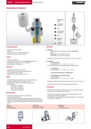
ACCUMULATORS<br />
• General Information . . . . . . . . . . . . . . . . . . . . . . . . . . . . . . . . . . . . . . . . . . . . . . . . .A44<br />
• Specifications . . . . . . . . . . . . . . . . . . . . . . . . . . . . . . . . . . . . . . . . . . . . . . . . . . . . .A45<br />
• Design Features and Benefits . . . . . . . . . . . . . . . . . . . . . . . . . . . . . . . . . . . . . . . . .A46<br />
• 3000 PSI Bottom Repairable ASME Standard . . . . . . . . . . . . . . . . . . . . . . . . . . . .A47<br />
• 3000 PSI Top Repairable ASME Standard . . . . . . . . . . . . . . . . . . . . . . . . . . . . . . .A48<br />
• 5000 PSI Bottom Repairable ASME Standard . . . . . . . . . . . . . . . . . . . . . . . . . . . .A49<br />
• Bladder Accumulators Ordering Code . . . . . . . . . . . . . . . . . . . . . . . . . . . . . . . . . .A50<br />
• Bladder Part Numbers . . . . . . . . . . . . . . . . . . . . . . . . . . . . . . . . . . . . . . . . . . . . . . .A51<br />
• Charge Kit, Repair Kit & Port Adaptors . . . . . . . . . . . . . . . . . . . . . . . . . . . . . . . . .A52<br />
• Accumulators Brackets . . . . . . . . . . . . . . . . . . . . . . . . . . . . . . . . . . . . . . . . . . . . . .A53<br />
• Accumulator Base Brackets & Rubber Rings . . . . . . . . . . . . . . . . . . . . . . . . . .A54-55<br />
• Accumulator U-Bolts RBD Series . . . . . . . . . . . . . . . . . . . . . . . . . . . . . . . . . . . . . .A56<br />
• Operating & Maintenance Instructions . . . . . . . . . . . . . . . . . . . . . . . . . . . . . . .A57-59<br />
• Disassembling Instructions . . . . . . . . . . . . . . . . . . . . . . . . . . . . . . . . . . . . . . . . . . .A60<br />
• Re-Assembling Instructions . . . . . . . . . . . . . . . . . . . . . . . . . . . . . . . . . . . . . . . . . .A61<br />
• Sizing Data & Applications . . . . . . . . . . . . . . . . . . . . . . . . . . . . . . . . . . . . . . . .A62-67<br />
ACCESSORIES<br />
A1
Suction Strainer SUS Series - Aluminum End Cap<br />
Specifications<br />
• Stainless Steel Mesh 125µ—100 Mesh<br />
• Temperature to 250˚F (+120˚C)<br />
• Epoxy Bonded for Compatibility with most<br />
Petroleum & Mineral Based Fluids.<br />
• Aluminum Threaded End Cap, other<br />
Components Steel Zinc Plated<br />
Options<br />
• No By-pass or 3 PSI By-pass Available<br />
• Custom Sizes on Request<br />
• Custom Mesh on Request<br />
(60µ or 250µ)<br />
• Available in BSP on<br />
Request<br />
1.0<br />
0.8<br />
0.6<br />
0.4<br />
.02<br />
Flow rates vs. P on 100 Mesh—125Micron Elements using 150SSU Oil at 100˚F<br />
100GPM-3"<br />
.07<br />
.06<br />
.05<br />
.03<br />
.02<br />
Pressure Drop—Bars<br />
Technical Information<br />
Dimensions<br />
SW<br />
L<br />
<strong>Hydraulic</strong> Symbol<br />
øD1<br />
G<br />
øD2<br />
PSI<br />
10 20 30 40 50 60 70 80 90 100 110 120 GPM<br />
without bybass valve<br />
with bypass valve<br />
38 114 190 266 380 450 Liters per minute<br />
Dimensions / Ordering Information<br />
ACCESSORIES<br />
Group Size<br />
Upper End Thread Element<br />
Diameter Code Length<br />
050 - N06F - 090<br />
050 - N08F - 105<br />
068 - N12F - 105<br />
068 - N16F - 140<br />
088 - N20F - 195<br />
088 - N24F - 226<br />
088 - N24F - 260<br />
088 - N32F - 260<br />
150 - N40F - 213<br />
150 - N48F - 272<br />
Ordering Code<br />
Diameter<br />
Port (G) Nominal Flow Filter Area Length L øD1 øD2 SW Wt.<br />
(NPT) gpm l/min in 2 cm 2 mm in mm in mm in mm in (lb.)<br />
3/8" 3 11 20 130 90 3.5 50 2.0 49 1.9 26 1.0 0.3<br />
1/2" 5 19 25 161 105 4.1 50 2.0 49 1.9 26 1.0 0.4<br />
3/4" 8 31 62 400 105 4.1 68 2.7 66 2.6 34 1.3 0.5<br />
1" 10 38 110 710 139 5.5 68 2.7 66 2.6 42 1.7 0.7<br />
1 1/4" 20 88 162 1050 195 7.7 88 3.5 85 3.3 60 2.4 1.0<br />
1 1/2" 30 120 225 1450 226 8.9 88 3.5 85 3.3 60 2.4 1.2<br />
1 1/2" 50 198 340 2190 260 10.0 88 3.5 85 3.3 60 2.4 1.4<br />
2" 50 198 340 2190 260 10.0 88 3.5 85 3.3 70 2.8 1.8<br />
2 1/2" 75 283 400 2580 213 8.4 150 5.9 145 5.7 90 3.5 2.3<br />
3" 100 379 500 3230 272 10.7 150 5.9 145 5.7 100 3.5 3.0<br />
SUS - A - 088 - N24F - 226 - 125 - 0<br />
Type<br />
Bypass Option<br />
SUS Suction Strainer 0 without bypass (standard)<br />
3 integrated bypass valve<br />
Material Threaded End Cap<br />
(0,2 bar / 3 PSI)<br />
A Aluminium (only for NPT thread, see table)<br />
Micron Rating<br />
060 60 µm (on request)<br />
Group Size<br />
125 125 µm (standard)<br />
250 250 µm (on request)<br />
see table above, column group size<br />
A2
Suction Strainer SUS Series - Plastic End Cap<br />
Specifications<br />
• Stainless Steel Mesh 125µ—100 Mesh<br />
• Temperature to 250˚F (+120˚C)<br />
• Epoxy Bonded for Compatibility with most<br />
Petroleum & Mineral Based Fluids.<br />
• Plastic Threaded End Cap made out of Glass<br />
Fiber Reinforced Polyamide. Other Components<br />
Steel Zinc Plated<br />
Technical Information<br />
Dimensions<br />
L<br />
øD1<br />
G<br />
Options<br />
• No By-pass or 3 PSI By-pass Available<br />
• Custom Sizes on Request<br />
• Custom Stainless Mesh<br />
on Request (60µ, on 250µ)<br />
1.0<br />
• Available in BSP on<br />
Request<br />
0.8<br />
0.6<br />
0.4<br />
.02<br />
Flow rates vs. P on 100 Mesh—125Micron Elements using 150SSU Oil at 100˚F<br />
100GPM-3"<br />
.07<br />
.06<br />
.05<br />
.03<br />
.02<br />
Pressure Drop—Bars<br />
SW<br />
<strong>Hydraulic</strong> Symbol<br />
øD2<br />
PSI<br />
10 20 30 40 50 60 70 80 90 100 110 120 GPM<br />
without bybass valve<br />
with bypass valve<br />
38 114 190 266 380 450 Liters per minute<br />
Dimensions / Ordering Information<br />
Group Size<br />
Upper End Thread Element<br />
Diameter Code Length<br />
050 - N06F - 090<br />
050 - N08F - 105<br />
068 - N12F - 105<br />
068 - N16F - 140<br />
088 - N20F - 140<br />
088 - N24F - 140<br />
102 - N24F - 200<br />
102 - N32F - 260<br />
131 - N40F - 212<br />
131 - N48F - 272<br />
Ordering Code<br />
Diameter<br />
Port (G) Nominal Flow Filter Area Length L øD1 øD2 SW Wt.<br />
(NPT) gpm l/min in 2 cm 2 mm in mm in mm in mm in (lb.)<br />
3/8" 3 11 20 130 90 3.5 50 1.9 49 1.9 26 1.0 0.3<br />
1/2" 5 19 25 161 105 4.1 50 1.9 49 1.9 26 1.0 0.4<br />
3/4" 8 31 62 400 105 4.3 68 2.6 66 2.6 34 1.3 0.5<br />
1" 10 38 110 710 140 5.5 68 2.6 66 2.6 42 1.7 0.7<br />
1 1/4" 20 88 105 1050 140 5.5 88 3.5 85 3.3 60 2.4 1.0<br />
1 1/2" 30 120 225 1450 140 5.5 88 3.5 85 3.3 60 2.4 1.2<br />
1 1/2" 50 198 340 2190 200 7.9 102 3.9 100 3.9 72 2.8 1.4<br />
2" 50 198 340 2190 260 10.2 102 3.9 100 3.9 72 2.8 1.8<br />
2 1/2" 75 283 400 2580 212 8.4 131 5.1 128 5.0 86 3.4 2.3<br />
3" 100 379 500 3230 272 10.7 131 5.1 128 5.0 96 3.8 3.0<br />
SUS - P - 088 - N24F - 140 - 125 - 0<br />
ACCESSORIES<br />
Type<br />
Bypass Option<br />
SUS Suction Strainer 0 without bypass (standard)<br />
3 integrated bypass valve<br />
Material Threaded End Cap<br />
(0,2 bar / 3 PSI)<br />
P Polyamide (only for NPT thread, see table)<br />
Micron Rating<br />
060 60 µm (on request)<br />
Group Size<br />
125 125 µm (standard)<br />
250 250 µm (on request)<br />
see table above, column group size<br />
A3
Suction Strainers - TMF Series NPT Tank Mounted<br />
Specifications<br />
• Stainless Steel Mesh 100 Mesh - 125 Micron<br />
• Cast Iron Bushing<br />
• Epoxy Bonded for Compatibility with most<br />
Petroleum & Mineral Based Fluids<br />
• Perforated Steel Inner Supports<br />
• Temperature to 250°F (120°C)<br />
Options<br />
• No By-Pass or 5 PSI By-Pass<br />
• Custom Screens Available upon Request<br />
• Custom Adaptors Available upon Request<br />
Dimensions / Mounting Information<br />
A<br />
B<br />
F<br />
E<br />
D<br />
C<br />
ACCESSORIES<br />
Ordering Information<br />
Part<br />
No. Flowrate NPT Sizes C D<br />
Hex<br />
F E<br />
Screen<br />
Area<br />
gpm lpm A B mm in mm in mm in mm in cm 2 in 2<br />
TMF-03-0 5 19 1" 3/8" 135 5.3 27 1.1 41 1.6 29 1.2 258 40<br />
TMF-05-0 5 19 1" 1/2" 135 5.3 27 1.1 41 1.6 29 1.2 258 40<br />
TMF-10-0 10 38 1 1/4" 3/4" 207 8.2 30 1.2 46 1.8 34 1.4 432 67<br />
TMF-15-0 15 57 1 1/2" 1" 208 8.2 31 1.2 55 2.2 42 1.7 554 86<br />
TMF-25-0 25 95 2" 1 1/4" 230 9.0 35 1.4 65 2.6 54 2.1 1025 159<br />
TMF-50-0 50 189 3" 2" 246 9.7 43 1.7 98 3.3 76 3.0 1625 252<br />
TMF-100-0 100 378 4" 3" 287 11.3 46 1.8 120 4.8 101 4.0 2032 315<br />
By-Pass Option<br />
Part<br />
No. Flowrate NPT Sizes C D<br />
Hex<br />
F E<br />
Screen<br />
Area<br />
gpm lpm A B mm in mm in mm in mm in cm 2 in 2<br />
TMF-03-5 5 19 1" 3/8" 135 5.3 27 1.1 41 1.6 29 1.2 258 40<br />
TMF-05-5 5 19 1" 1/2" 135 5.3 27 1.1 41 1.6 29 1.2 258 40<br />
TMF-10-5 10 38 1 1/4" 3/4" 207 8.2 30 1.2 46 1.8 34 1.4 432 67<br />
TMF-15-5 15 57 1 1/2" 1" 208 8.2 31 1.2 55 2.2 42 1.7 554 86<br />
TMF-25-5 25 95 2" 1 1/4" 230 9.0 35 1.4 65 2.6 54 2.1 1025 159<br />
TMF-50-5 50 189 3" 2" 246 9.7 43 1.7 98 3.3 76 3.0 1625 252<br />
TMF-100-5 100 378 4" 3" 287 11.3 46 1.8 120 4.8 101 4.0 2032 315<br />
A4
Suction Strainers - TMF Series SAE O-Ring Tank Mounted<br />
Specifications<br />
• SAE O-Ring Threads for Leak-Free Installation<br />
• Buna O-Ring Standard<br />
• 100 Mesh (125 Micron) Stainless Wire Screen<br />
• Flow Rates to 40 gpm<br />
• Temperature to 212°F (100°C)<br />
Options<br />
• 5 PSI Bypass<br />
• Weld Flange Available (WC Series - Page A7)<br />
• Consult Factory for Special Screens and Threads<br />
Dimensions<br />
hex size<br />
Installation With Weld Flange WC (Supplied separately)<br />
D<br />
C<br />
Weld Flange<br />
E<br />
Thread B<br />
Thread A<br />
1. Weld Flange to Tank 2. Screw Strainer into Flange<br />
Ordering Information<br />
Thread<br />
Hex<br />
Part No. Part No. (Per SAE J514) C D E Size Flow Area<br />
Non-Bypass Bypass<br />
A B mm in mm in mm in mm in lpm gpm cm 2 sq. in<br />
TMF-1625-0-0 TMF-1625-0-5 2 1 /2"-12 1 5 /16"-12 229 9.0 19 0.75 58 2.3 54 2.1 34 9 580 90<br />
TMF-2025-0-0 TMF-2025-0-5 2 1 /2"-12 1 5 /8"-12 229 9.0 19 0.75 58 2.3 54 2.1 53 14 580 90<br />
TMF-1834-0-0 TMF-1834-0-5 3 3 /8"-12 1 7 /8"-12 224 8.8 23 0.9 80 3.1 64 2.5 80 21 1484 230<br />
TMF-2534-0-0 TMF-2534-0-5 3 3 /8"-12 2 1 /2"-12 236 9.3 25 1.0 80 3.1 76 3.0 148 39 1484 230<br />
ACCESSORIES<br />
A5
Suction Strainers - TMF-HB Series Hose Barb Tank Mounted<br />
Specifications<br />
• Hose Barb to O-Ring Installation<br />
• SAE O-Ring Thread for Leak-Free Installation<br />
• Buna O-Ring<br />
• 100 Mesh (125 Micron) Stainless Wire Screen<br />
• Temperature to 212°F (100°C)<br />
Options<br />
• 5 PSI Bypass<br />
• Viton O-Ring<br />
• Weld Flange Available (see WC Series - Page A7)<br />
• Consult Factory for Special Screens and Threads<br />
Dimensions<br />
Hex Size<br />
L2<br />
L3<br />
Thread A<br />
L1L<br />
L1<br />
O.D.<br />
E<br />
ACCESSORIES<br />
Ordering Information<br />
Part No. Part No. Thread O. D. L L1 L2 L3 E Hex Size<br />
Non-Bypass Bypass Size A mm in mm in mm in mm in mm in mm in mm in<br />
TMF-1017HB-0-0 TMF-1017HB-0-5 1 7/8"-12 25 1.0 236 9.3 185 7.3 51 2.0 32 1.25 42 1.6 32 1.25<br />
TMF-1225HB-0-0 TMF-1225HB-0-5 2 1/2"-12 32 1.25 254 10.0 203 8.0 51 2.0 32 1.25 54 2.1 38 1.5<br />
TMF-1234HB-0-0 TMF-1234HB-0-5 3 3/8"-12 32 1.25 261 10.3 198 7.8 64 2.5 38 1.5 82 3.2 51 2.0<br />
TMF-1534HB-0-0 TMF-1534HB-0-5 3 3/8"-12 38 1.5 261 10.3 198 7.8 64 2.5 38 1.5 82 3.2 51 2.0<br />
TMF-2034HB-0-0 TMF-2034HB-0-5 3 3/8"-12 51 2.0 274 10.8 199 7.8 76 3.0 51 2.0 82 3.2 63 2.5<br />
A6
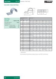
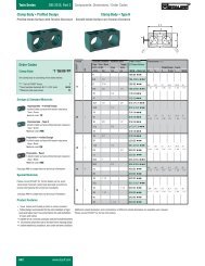
Suction Strainers - WC Series SAE O-Ring Weld Flanges<br />
Specifications<br />
• Forged Steel<br />
• Designed for Minimum Weld Distortion<br />
• Pilot Minimizes Installation Setup<br />
Dimensions<br />
Port Size<br />
(per SAE J514)<br />
D<br />
Weld Flange<br />
E<br />
B<br />
A<br />
C<br />
Application Example using SAE O-Ring Tank Mounted Strainer<br />
(Supplied separately)<br />
Ordering Information<br />
Part No. Port Size A B C D E<br />
mm in mm in mm in mm in mm in<br />
WC-1017 1 7/8"-12 76 3.0 57 2.3 19 0.8 13 0.5 60 2.4<br />
WC-1225 2 1/2"-12 89 3.5 52 2.0 21 0.8 15 0.6 73 2.9<br />
WC-1634 3 3/8"-12 118 4.6 93 3.7 25 1.0 21 0.8 100 3.9<br />
ACCESSORIES<br />
A7
Diffusers - SRV Series<br />
Specifications<br />
• Reduces Fluid Aeration & Noise in Oil Tanks<br />
• Aluminum End Cap - Other Metal Parts are Zinc Plated<br />
• Operating Temperature -13˚F(-25˚C) to 212˚F(100˚C)<br />
• NPT Thread<br />
• Flow Range to 250 GPM (950 lpm)<br />
• Maximum Working Pressure 300 PSI (20 bar)<br />
Options<br />
• Available in BSP on Request<br />
• Custom Designs Available on Request<br />
Dimensions<br />
NOTE<br />
SRV must be installed below liquid level.<br />
Plain area should face pump inlet.<br />
SW<br />
L<br />
D2<br />
G<br />
D1<br />
160°<br />
Perforated Area<br />
ACCESSORIES<br />
Ordering Code and Dimensions Table<br />
Part No. Thread Size G Max. Flow Length L Dia. D1 Dia. D2 Hex SW<br />
gpm lpm mm in mm in mm in mm in<br />
SRV-050-N12 3<br />
/4" NPT 13 50 109 4.3 64 2.5 60 2.4 36 1.4<br />
SRV-114-N16 1" NPT 30 114 139 5.5 64 2.5 60 2.4 46 1.9<br />
SRV-200-N20 1 1 /4" NPT 53 200 139 5.5 86 3.4 82 3.2 60 2.4<br />
SRV-227-N24 1 1 /2" NPT 60 227 200 7.9 86 3.4 82 3.2 60 2.4<br />
SRV-454-N32 2" NPT 120 454 260 10.2 86 3.4 82 3.2 70 2.8<br />
SRV-650-N40 2 1 /2" NPT 180 680 211 8.3 150 5.7 145 5.7 90 3.5<br />
SRV-950-N48 3" NPT 250 950 272 10.7 150 5.7 145 5.7 100 3.9<br />
A8
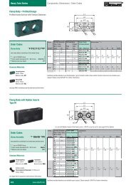
Metal Filler Breathers SMBB / SMBT / SMBP<br />
Area of Application:<br />
Reservoir Breathers and Tank Filling<br />
Available Versions:<br />
Screw-in, bayonet and push-on style<br />
Materials:<br />
• Breather cap: steel, chrome-plated or epoxy – coated.<br />
• Bayonet Flange: steel, chrome-plated<br />
• Air filter insert: 3µ, 10µ or 40µ in group size 80<br />
10µ or 40µ in group size 47<br />
• Basket: steel, zinc-plated<br />
• Seals:<br />
Cork - Group 47 or 80 standard breathers<br />
Buna-N - Group 80 pressurized breathers<br />
Options:<br />
• Baskets – Additional 6" (150 mm), 8" (200 mm) steel mesh and 4" (100 mm)<br />
plastic baskets available with “Group Size 80”<br />
• Thread style – NPT standard, BSP available on request<br />
• Pressurized – 5 PSI (0.35 bar) or 10 PSI (0.70 bar) Relief valve settings<br />
• Locking tabs<br />
• Push-on style<br />
• Dipsticks<br />
• Custom versions available on request<br />
Group size 47 – Breather cap diameter 47 mm<br />
SMBB-47<br />
Metal Filler Breather<br />
Bayonet style<br />
Seal material: cork<br />
Options:<br />
• Metal basket<br />
BCD=ø41 (ø1.61")<br />
ø29 (ø1.14")<br />
Mounting Detail<br />
3x ø5.5 (ø0.22") THRU<br />
FOR #10-32UNF<br />
SELF TAPPING<br />
SCREW<br />
SMBT-47<br />
Metal Breather<br />
Screw-in style<br />
Options:<br />
• NPT-thread standard (1/4" NPT, 3/8" NPT)<br />
BSP optional. Other threading – consult factory<br />
ø47 (ø1.85")<br />
ø47 (ø1.85")<br />
45 (1.77")<br />
65 (2.56")<br />
3x #10-32UNF x<br />
12.7 (0.5")<br />
SDF TAPPING<br />
SCREW<br />
45 (1.67")<br />
12.5 (0.49")<br />
G<br />
SW<br />
Type<br />
SMBT-47 N04 N06<br />
G 1/4" NPT 3/8" NPT<br />
SW 17 (0.7") 19 (0.2")<br />
ACCESSORIES<br />
ø28 (ø1.10")<br />
BCD=ø41 (ø1.61")<br />
Part No. Micron Rating Air Flow Capacity Oil Displacement Screws<br />
cfm m 3 /min gpm lpm<br />
SMBB 47/SMBT 47 10 10 0.28 72 272 10-32x1/2<br />
SMBB 47/SMBT 47 40 14 0.4 90 340 10-32x1/2<br />
Metal Filler breathers SMBB-47 and SMBT-47 are not available in pressurized or lockable versions. For more details review the<br />
ordering table on page A10.<br />
A9
Metal Filler Breathers SMBB / SMBT / SMBP<br />
Ordering Code (bayonet style, cap ø47)<br />
SMBB - 47E - N - 10 - O - C - S065 - O<br />
Type<br />
SMBB<br />
Cap Size<br />
S<br />
N<br />
Metal Filler Breather<br />
(bayonet style)<br />
47 ø47, steel cap, chrome-plated (standard)<br />
47E ø47, steel cap, black epoxy<br />
Note: other versions available upon request<br />
Version<br />
with STAUFF-logo (standard)<br />
neutral (without logo)<br />
Filter Material and Micron Rating<br />
00 without filter insert<br />
10 10 µm foam (PUR)<br />
40 40 µm foam (PUR)<br />
Dipstick<br />
O without dipstick (standard)<br />
Baskets<br />
O without baskets<br />
S065 65 mm metal basket (standard)<br />
Seal Material<br />
C cork<br />
Pressurisation (Opening Pressure)<br />
O without pressurisation (standard)<br />
Note: No pressurisation available for this cap diameter.<br />
Note: Screws are supplied with the SMBB as standard<br />
Ordering Code (screw-in style, cap ø47)<br />
SMBT - 47E - N - 10 - O - N06 - O<br />
ACCESSORIES<br />
Type<br />
SMBT<br />
Cap Size<br />
S<br />
N<br />
Metal Filler Breather<br />
(screw-in style)<br />
47 ø47, steel cap, chrome-plated (standard)<br />
47E ø47, steel cap, black epoxy<br />
Note: other versions available upon request<br />
Version<br />
with STAUFF-logo (standard)<br />
neutral (without logo)<br />
Filter Material and Micron Rating<br />
00 without filter insert<br />
10 10 µm foam (PUR, standard)<br />
40 40 µm foam (PUR)<br />
N04 1<br />
/4<br />
N06 3<br />
/8<br />
Dipstick<br />
O without dipstick (standard)<br />
Connection Thread<br />
1<br />
/4 NPT<br />
3<br />
/8 NPT<br />
Note: Other connection threads and sizes<br />
available<br />
Pressurisation (Opening Pressure)<br />
O without pressurisation (standard)<br />
Note: No pressurisation available for this cap diameter.<br />
A10
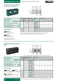
Metal Filler Breathers SMBB / SMBT / SMBP<br />
Group size 80 – Breather cap diameter 80 mm<br />
SMBB-80<br />
Metal Filler Breather<br />
Bayonet style, 3" metal basket standard<br />
Options:<br />
• Metal Dipstick – non-pressurized<br />
• Plastic Dipstick – pressurized<br />
• Locking version<br />
• Pressurized, opening<br />
pressure 5 PSI (0.35 bar) and 10 PSI<br />
(0.7 bar)<br />
• Seal material: cork – non-pressurized<br />
Buna-N – pressurized<br />
• 6" (150 mm) and 8" (200 mm) metal<br />
and 4” (100 mm) plastic baskets<br />
available<br />
• 3µ, 10µ or 40 micron breather element<br />
• Chrome plated or epoxy coated<br />
• Extended Bayonet options available<br />
SMBT-80<br />
Metal Breather<br />
Screw-in style<br />
Options:<br />
• Metal Dipstick non-pressurized<br />
• Plastic Dipstick – pressurized<br />
• NPT thread standard, BSP available<br />
on request<br />
• Pressurized, opening<br />
pressure 5 PSI (0.35 bar) or 10 PSI<br />
(0.7 bar)<br />
• 3µ, 10µ or 40 micron breather element<br />
• Chrome plated or epoxy coated<br />
SMBP-80<br />
Metal Breather, epoxy coated standard<br />
Push-on style<br />
Options:<br />
• Plastic Dipstick<br />
BCD=ø73 (ø2.87")<br />
ø52 (ø2.05")<br />
ø80 (ø3.15")<br />
6x ø5.5 (ø0.22")<br />
THRU FOR<br />
#10-32UNF<br />
SELF TAPPING<br />
SCREW<br />
51 (2.01")<br />
ø80 (ø3.15")<br />
53 (2.09")<br />
6x #10-32UNF<br />
x 12.7 (0.5") LG<br />
SDF TAPPING<br />
SCREWS<br />
H1<br />
SW<br />
G<br />
42 (1.65")<br />
80/150/200 (3.15"/5.91"/7.87")<br />
ø50 (ø1.97")<br />
BCD=ø73 (ø2.87")<br />
ø6.5<br />
(ø0.26")<br />
Type<br />
SMBT-80 N08 N12 N16<br />
G 1/2" NPT 3/4" NPT 1" NPT<br />
H1 14 16 19<br />
SW 24 30 36<br />
ø38 (ø1.50")<br />
ø81 (ø3.19")<br />
Non-pressurized version Non-pressurized version The SMBP is only available without<br />
pressurization<br />
BCD=ø73 (ø2.87")<br />
53 (2.09")<br />
80/150/200 (3.15"/5.91"/7.87")<br />
ø52 (ø2.05")<br />
ø80 (ø3.15")<br />
ø50 (ø1.97")<br />
BCD=ø73 (ø2.87")<br />
6x ø5.5 (ø0.22")<br />
THRU FOR<br />
#10-32UNF<br />
SELF TAPPING<br />
SCREW<br />
6x #10-32UNF<br />
x 12.7 (0.5") LG<br />
SDF TAPPING<br />
SCREWS<br />
ø6.5<br />
(ø0.26")<br />
51 (2.01")<br />
H1<br />
SW<br />
ø80 (ø3.15")<br />
Type<br />
SMBT-80 N08 N12 N16<br />
G 1/2" NPT 3/4" NPT 1" NPT<br />
H1 14 16 19<br />
SW 24 30 36<br />
G<br />
Bayonet Flange Options<br />
Standard Bayonet - “B”<br />
Part No. EBF-1 - “B1”<br />
38 mm (1.5 in) high<br />
(See A13 for details)<br />
Part No. EBF-2 - “B2”<br />
69 mm (2.7 in) high<br />
(See A13 for details)<br />
ACCESSORIES<br />
Pressurized version<br />
Pressurized version<br />
Part No. Micron Rating Air Flow Capacity Oil Displacement Screws<br />
cfm m 3 /min gpm lpm<br />
SMBB/SMBT 80 3 10 0.28 72 272 10-32x1/2<br />
SMBB/SMBT 80 10 16 0.45 110 416 10-32x1/2<br />
SMBB/SMBT 80 40 26 0.75 190 720 10-32x1/2<br />
A11
Metal Filler Breathers SMBB / SMBT / SMBP<br />
Ordering Code (bayonet style, cap ø80)<br />
SMBB - 80E - N - L - 10 - 05 - B - S080 - O<br />
Type<br />
SMBB<br />
Metal Filler Breather<br />
(bayonet style)<br />
Cap Size<br />
80 ø80, steel cap, chrome-plated (standard)<br />
80E ø80, steel cap, black epoxy<br />
Note: other versions on request<br />
Version<br />
S with STAUFF-logo (standard)<br />
N neutral (without logo)<br />
Locking Option<br />
O not lockable (standard)<br />
L lockable<br />
Filter Material and Micron Rating<br />
00 without filter insert<br />
03 3 µm filter paper<br />
10 10 µm foam (PUR, standard)<br />
40 40 µm foam (PUR)<br />
Dipstick<br />
O without dipstick (standard)<br />
D300 plastic dipstick 300 mm<br />
Note: The plastic dipstick can be shortened<br />
by the customer to requested lengths.<br />
Baskets<br />
O without baskets<br />
S080 80 mm metal basket (standard)<br />
P100 100 mm plastic basket<br />
S150 150 mm metal basket<br />
S200 200 mm metal basket<br />
Seal Material<br />
C cork (for non-pressurised version)<br />
B NBR (for pressurised version)<br />
Pressurisation (Opening Pressure)<br />
O without pressurisation (standard)<br />
05 0,35 bar (5 PSI)<br />
10 0,70 bar (10 PSI)<br />
Note: Screws are supplied with the SMBB as standard<br />
Ordering Code (screw-in style, cap ø80)<br />
SMBT - 80E - N - 10 - 05 - N12 - O<br />
ACCESSORIES<br />
Type<br />
SMBT<br />
Metal Filler Breather<br />
(screw-in style)<br />
Cap Size<br />
80 ø80, steel cap, chrome-plated (standard)<br />
80E ø80, steel cap, black epoxy<br />
Note: other versions on request<br />
Version<br />
S with STAUFF-logo (standard)<br />
N neutral (without logo)<br />
Filter Material and Micron Rating<br />
00 without filter insert<br />
03 3 µm filter paper<br />
10 10 µm foam (PUR, standard)<br />
40 40 µm foam (PUR)<br />
Ordering Code (push-on style, cap ø80)<br />
Type<br />
SMBP<br />
Metal Filler Breather<br />
(push-on style)<br />
Cap Size<br />
80 ø80, steel cap, chrome-plated<br />
80E ø80, steel cap, black epoxy (standard)<br />
Note: other versions on request<br />
Version<br />
S with STAUFF-logo (standard)<br />
N neutral (without logo)<br />
SMBP - 80E - N - 10 - D300<br />
A12<br />
Dipstick<br />
O without dipstick (standard)<br />
D300 plastic dipstick 300 mm<br />
Note: The plastic dipstick can be shortened<br />
by the customer to requested lengths.<br />
Connection Thread<br />
N08 1<br />
/2 NPT<br />
N12 3<br />
/4 NPT<br />
N16 1 NPT upon request<br />
B08 G 1 /2 BSP upon request<br />
B12 G 3 /4 BSP upon request<br />
B16 G 1 BSP upon request<br />
Pressurisation (Opening Pressure)<br />
O without pressurisation (standard)<br />
05 0,35 bar (5 PSI)<br />
10 0,70 bar (10 PSI)<br />
Dipstick<br />
O without dipstick (standard)<br />
D300 plastic dipstick 300 mm<br />
Note: The plastic dipstick can be shortened<br />
by the customer to requested lengths.<br />
Filter Material and Micron Rating<br />
00 without filter insert<br />
10 10 µm foam (PUR, standard)<br />
40 40 µm foam (PUR)
Filler Breather Options<br />
Side Mounting Bracket – SMBB–ASMB–1<br />
Area of Application:<br />
Allows side mounting of filler breathers where application has space limitations<br />
(suitable for SMBB-80 and SPB 5)<br />
Materials:<br />
• Housing:<br />
SMBB-ASMB-1<br />
Polyamide<br />
• Seals:<br />
Composite gasket<br />
• Screws:<br />
Steel, zinc-plated<br />
M6x 25 DIN 912<br />
• Nuts: Steel, zinc-plated M6 DIN 934<br />
• Washers: Steel, zinc-plated<br />
• Mounting screws: Steel, zinc-plated 4.8x13 DIN 7981<br />
Seals, screws, washers and nuts are supplied with the SMBB-ASMB as standard<br />
Dimensions SMBB-ASMB-1<br />
Dimensions in mm (inch)<br />
29.5<br />
(1.18")<br />
117.0 (4.61")<br />
102.0 (4.02")<br />
86.0 (3.39")<br />
1.5 (0.06")<br />
73.4 (2.89")<br />
ø51.0<br />
5.5 (0.22")<br />
(ø2.01")<br />
THRU<br />
41° BCD = ø71.0 (ø2.80")<br />
42.2 (1.66")<br />
148 (5.83")<br />
51.0 (2.01")<br />
51.0 (2.01")<br />
6x ø4.5 (ø0.18") THRU<br />
8.5 (0.33")<br />
~3.19 (81.0")<br />
Dipstick Options<br />
Metal (available on all models)<br />
FULL<br />
OVERALL<br />
OVERALL<br />
LENGTH<br />
LENGTH<br />
FULL<br />
ADD<br />
ADD<br />
• Dipsticks can be custom marked as requested.<br />
• Plastic Dipsticks – 300 mm max for pressurized versions<br />
• Metal Dipsticks – 380 mm max for non-pressurized version<br />
• Provide factory with drawing of markings required<br />
Additional Baskets Weld Riser Extended Bayonet Flange<br />
ACCESSORIES<br />
4"<br />
100 mm<br />
Plastic Metal Metal<br />
Part number<br />
S-095-P-F<br />
6"<br />
152 mm<br />
Part number<br />
S150<br />
8"<br />
203 mm<br />
Part number<br />
S200<br />
1.12"<br />
(28.5 mm)<br />
Standard 6 bolt pattern<br />
Part number WR-1<br />
A13<br />
3.54"<br />
(90 mm)<br />
A<br />
B<br />
Dimension Table<br />
Dimensions<br />
A B<br />
Part No. mm in mm in<br />
EBF-1 38 1.5 88 3.4<br />
EBF-2 69 2.7 88 3.4
1 5<br />
Metal Filler Breathers (Lockable), SMBL Series<br />
Area of Application:<br />
Reservoir breathers and tank filling<br />
Characteristics/Materials:<br />
• available as thread-style, clamping style and push-on-style<br />
• key-lockable<br />
• Temperature range: -22°F (-30°C) to 212°F (100°C)<br />
• Materials:<br />
Body:<br />
die cast (zinc-plated / blue chromated)<br />
Baskets: zinc-plated steel or polypropylene (see ordering code)<br />
Seals:<br />
Buna-N, others on request<br />
Air filter insert: 10 µm (standard) and 40 µm foam (PUR), others are<br />
available upon request<br />
• Including two keys<br />
Dimensions<br />
Dimensions in mm (inch)<br />
SMBL C-...-S150<br />
clamp style<br />
with steel<br />
basket<br />
max. 125°<br />
min 165<br />
(6.5")<br />
SMBL C-...-S200<br />
clamp style with<br />
telescope basket (PP)<br />
SMBL B/P-...-0<br />
thread or push-on style<br />
without basket<br />
79 mm 70 mm<br />
(3.1") (2.8")<br />
149 mm<br />
(5.9")<br />
48.<br />
30 mm<br />
(5.1") (1.9")<br />
Ø50<br />
(2.0")<br />
Ø77± 1<br />
(3.0")<br />
10 mm<br />
(0.4")<br />
max<br />
185<br />
max<br />
min 85 mm<br />
(7.3")<br />
(3.3")<br />
Ø29.5 (1.16")<br />
Ø41.5 (1.64")<br />
Ø77± 1 (3.0")<br />
10<br />
max<br />
(0.4")<br />
recommended<br />
clearance<br />
for thread-style<br />
R=81 mm<br />
(3.2")<br />
max 13.5<br />
(0.5")<br />
1<br />
2<br />
3<br />
34 (1.39”)<br />
107<br />
(4.2")<br />
2 screws DIN 916-M6x6 for thread style (pos.1+2)<br />
3 screws DIN 916-M6x6 for push-on-style (pos.1-3)<br />
Ordering Code<br />
SMBL C - 10 - 1 - S150 - B - O<br />
ACCESSORIES<br />
Type<br />
SMBL<br />
Connection<br />
B32<br />
B40<br />
C<br />
P<br />
Filler Breather (lockable)<br />
G2 (thread style)<br />
G2 1 /2 (thread style)<br />
clamping style<br />
push-on-style<br />
Micron Rating<br />
00 without air filter<br />
10 10 micron foam (standard) air filter<br />
40 40 micron foam air filter<br />
Baskets<br />
Metal Cap Design<br />
O<br />
lacquered gray<br />
RAL 9022 (standard)<br />
Seal Material<br />
B NBR (standard)<br />
V FPM<br />
O<br />
no basket<br />
S-100-P-H plastic basket 80 mm (See Page A16)<br />
S-150-M-H steel basket 150 mm (standard)<br />
S-200-P-H-T plastic basket 200 mm (See Page A16)<br />
Note: baskets from the SMBB-series cannot be used in<br />
conjunction with the SMBL breather type<br />
A14<br />
Style (Air Flow)<br />
1 air flow in both directions (standard)<br />
2 no air flow<br />
3 air flow only into the tank
Plastic Filler Breather SPB Series<br />
Area of Application:<br />
Reservoir breathers and tank filling<br />
Characteristics/Materials:<br />
• available as screw-in or bayonet version<br />
• non-corrosive<br />
• Temperature range: -40°F (-40°C ) to 248°F (120°C)<br />
• Materials: glassfibre reinforced PA, basket PP<br />
• Seals:<br />
Buna-N, others on request<br />
• Air filter insert: 10 µm foam (PUR), others are available upon request<br />
Custom built combinations and special requirements available upon request.<br />
Dimensions and Styles – Screw-in versions (Breathers)<br />
SPB 1 SPB 2 SPB 3<br />
ø101 (ø4.0")<br />
ø45<br />
(ø1.8")<br />
ø70 (ø2.76")<br />
47 (1.85")<br />
64 (2.52")<br />
75 (2.95")<br />
SW 27 (1.06")<br />
1/4" NPT<br />
3/8" NPT<br />
1/2" NPT<br />
3/4" NPT<br />
13.5<br />
(0.53")<br />
SW 30 (1.18")<br />
3/4" NPT<br />
Max Airflow Rate: 0.15m 3 /min (5.25 cfm) Max Airflow Rate: 0.4m 3 /min (14 cfm) Max Airflow Rate: 1.0m 3 /min (35 cfm)<br />
19.5<br />
(0.77")<br />
SW 36 (1.42")<br />
3/4" NPT<br />
1" NPT<br />
19.5<br />
(0.77")<br />
Dimensions and Styles – Bayonet version (Filler Breathers)<br />
10 (0.39")<br />
max<br />
SPB 4<br />
single hole reservoir installation<br />
ø101 (ø4.0")<br />
67.5 (2.66")<br />
9 7 (3.82")<br />
10 (0.39")<br />
max<br />
SPB 5<br />
six hole bolt pattern reservoir installation<br />
ø101 (ø4.0")<br />
67.5 (2.66")<br />
97 (3.82")<br />
Dimensions in mm (inch)<br />
Note:<br />
Installation<br />
of the SPB 5<br />
In order to install the<br />
SPB 5, 6 holes on a<br />
73 mm (2.87") bolt<br />
circle diameter are<br />
necessary. Depending<br />
on the material thickness,<br />
we recommend the<br />
following dimensions<br />
for the mounting holes<br />
(see chart):<br />
recommended values<br />
sheet hole<br />
thickness size<br />
mm in mm in<br />
1.20 .05 4.0 .16<br />
2.00 .08 4.1 .16<br />
3.15 .12 4.3 .17<br />
4.00 .16 4.3 .17<br />
5.00 .20 4.4 .17<br />
ACCESSORIES<br />
min ø63 (ø2.48")<br />
tapping<br />
screws<br />
6 x # 10 x 1<br />
sheet metal screw<br />
min ø63 (ø2.44")<br />
BCD = ø73 (ø2.87")<br />
Bolt delivery standard:<br />
Tapping screws (can<br />
optionally be replaced<br />
with normal M5 bolts<br />
by the customer).<br />
Max Airflow Rate: 1.0m 3 /min (35 cfm)<br />
Max Airflow Rate: 1.0m 3 /min (35 cfm)<br />
A15
Plastic Filler Breather SPB Series<br />
Breather options:<br />
• Dipsticks (material PA)<br />
• Pressurized versions (for SPB 2 up to SPB 5)<br />
• Baskets (for SPB 4 and SPB 5)<br />
• Thread form BSP (for SPB 1 up to SPB 3) - consult factory for availability<br />
Special executions available upon request.<br />
Photo: integrated<br />
anti-splash feature<br />
ACCESSORIES<br />
Ø D<br />
8.5<br />
(0.33")<br />
D200 = 200 (7.87")<br />
D300 = 300 (11.81")<br />
green<br />
red<br />
SPB 4 and SPB 5<br />
basket<br />
S-100-P-H S080<br />
3.4<br />
(0.13")<br />
with<br />
integrated<br />
anti-splash<br />
function<br />
adjustable<br />
telescopic basket<br />
S-200-P-H-T S200<br />
205 (8.1")<br />
Dipsticks and Anti-splash feature<br />
Dimensions in mm (inch)<br />
Adaptation form for type suitable dipstick Dimension ØD<br />
N04 SPB 1 n/a –<br />
N06 SPB 1 + 2 DS-1 10 (.39)<br />
N08 SPB 1 – 3 DS-2 14 (.55)<br />
N12 SPB 1 DS-2 14 (.55)<br />
N12 SPB 2 + 3 DS-3 18 (.71)<br />
N16 SPB 3 DS-3 18 (.71)<br />
S-100-P-H SPB 4 + 5 DS-3 18 (.71)<br />
S-200--P-H-T SPB 4 + 5 DS-3 18 (.71)<br />
X SPB 4 + 5 DS-3 18 (.71)<br />
For all filler breathers SPB 1 up to SPB 5, dipsticks (material polyamide) are available as<br />
an option. All these dipsticks have an integrated anti-splash function. This anti-splash<br />
feature protects the SPB from backspilling fluid and avoids an early air filter breakdown.<br />
For filler breathers without dipstick the anti-splash function is achieved by an integrated<br />
concave baffle. Because of its size the anti-splash function for the SPB 1 can only be<br />
achieved in conjunction with a dipstick. Depending on the chosen filler breather (see table<br />
above), dipsticks are available in a maximum of 300 mm lengths. Send factory a drawing<br />
on exact length and markings required.<br />
Pressurized versions:<br />
All filler breathers, except SPB 1, are available as pressurized breathers. In order to<br />
achieve an air flow, the tank pressure has to exceed the chosen pressure setting. This<br />
feature minimizes foaming and cavitation. Available pressure settings: 3 PSI (0.2 bar), 5<br />
PSI (0.35 bar) and 10 PSI (0.7 bar).<br />
Baskets for SPB 4 and 5<br />
For the filler breathers SPB 4 and SPB 5, 3.7” (95 mm) and 8” (200 mm) baskets<br />
(material polypropylene) are available as an option. All baskets have a<br />
reinforced 0.8 x 3.5 mm mesh. With the basket S-100-P-H and the telescopic<br />
basket S-200-P-H-T, rough dirt particles are filtered out of the medium and a<br />
smooth flow into the tank is being ensured.<br />
max<br />
105 (4.13")<br />
ø41.5<br />
(1.64")<br />
(1.16")<br />
ø29.5<br />
ø41.5<br />
(1.64")<br />
A16
Plastic Filler Breather SPB Series<br />
SPB - S - 2 - 10 - N12 - A - D300<br />
Type<br />
SPB<br />
Version<br />
S<br />
P1<br />
P2<br />
P3<br />
Plastic filler breather<br />
(Pressurisation not available for SPB 1)<br />
without pressurisation (standard)<br />
pressurised at 0.20 bar (3 PSI)<br />
pressurised at 0.35 bar (5 PSI)<br />
pressurised at 0.70 bar (10 PSI)<br />
Group Size<br />
size version<br />
cap max rate of air<br />
diameter flow (m 3 /min)<br />
1 screw-in version 45 0.15<br />
2 screw-in version 70 0.45<br />
3 screw-in version 101 1.05<br />
4 single hole reservoir installation 101 1.05<br />
5 six hole reservoir installation 101 1.05<br />
Micron Rating and Filtermaterial<br />
Connection<br />
Dipstick Option<br />
(none)<br />
D200<br />
D300<br />
without dipstick<br />
dipstick 200 mm<br />
dipstick 300 mm<br />
Anti-splash Option<br />
A<br />
O<br />
with anti-splash option (standard)<br />
without anti-splash option<br />
N04 1<br />
/4" NPT (for SPB 1)<br />
N06 3<br />
/8" NPT (for SPB 1)<br />
N08 1<br />
/2" NPT (for SPB 1)<br />
N12 3<br />
/4" NPT (for SPB 1, 2, or 3)<br />
N16 1" NPT (for SPB 3)<br />
S-100-P-H basket (for SPB 4 + 5)<br />
S-200-P-H-T telescopic basket (for SPB 4 + 5)<br />
X without basket (for SPB 4 + 5)<br />
* Consult factory for availability of BSP threads<br />
Anti-splash option not available on SPB-S1, 1 /4" and 3 /8" versions<br />
code foam (PUR) code Inorganic glassfiber (only SPB 3,4 and 5) code filterpaper (only SPB 3,4 and 5)<br />
10 10 µm PUR (standard) E03 3 µm inorganic glass fiber (pleated) L10 10 µm filter paper (pleated)<br />
40 40 µm PUR (on request)<br />
Other micron ratings or filtermaterial available upon request<br />
Airflow plastic filler breathers SPB 1 – 5<br />
SPB 1<br />
into/out of the tank<br />
SPB 2<br />
into/out of the tank<br />
SPB 3<br />
into/out of the tank<br />
p in bar<br />
0.07<br />
0.06<br />
0.05<br />
0.04<br />
0.03<br />
0.02<br />
0.01<br />
N04 (in/out)<br />
N06 (in/out)<br />
N08 (in/out)<br />
N12 (in/out)<br />
0.0<br />
0 0.03 0.06 0.09 0.12 0.15 0.18 Q in m 3 /min<br />
SPB 4 and 5<br />
into the tank<br />
p in bar<br />
0.8<br />
0.7<br />
0.6<br />
0.5<br />
0.4<br />
0.3<br />
0.2<br />
P3-N12(out)<br />
P2-N12 (out)<br />
Px-N12 (in)<br />
P1-N12 (out)<br />
0.1<br />
S-N12 (out)<br />
0.0<br />
S-N12 (in)<br />
0 0.15 0.3 0.45 Q in m 3 /min<br />
SPB 4 and 5<br />
out of the tank<br />
p in bar<br />
0.8<br />
P3-N12 (out)<br />
0.7<br />
0.6<br />
0.5<br />
0.4<br />
0.3<br />
P2-N12 (out)<br />
Px-N12 (in)<br />
P1-N12 (out)<br />
0.2<br />
0.1<br />
S-N12 (in/out)<br />
0.0<br />
0 0.2 0.4 0.6 0.8 1.0 Q in m 3 /min<br />
ACCESSORIES<br />
p in bar<br />
0.8<br />
0.7<br />
p in bar<br />
0.8 P3<br />
0.7<br />
0.6<br />
0.5<br />
0.4<br />
0.3<br />
0.2<br />
0.1<br />
S<br />
0.0<br />
0 0.2 0.4 0.6 0.8 1.0 Q in m 3 /min<br />
Px<br />
0.6<br />
0.5<br />
0.4<br />
0.3<br />
0.2<br />
0.1<br />
P2<br />
P1<br />
0.0<br />
0 0.2 0.4 0.6 0.8 1.0 Q in m 3 /min<br />
S<br />
A17
Plastic Filler Breather SES Series<br />
Area of Application:<br />
Ventilation and tank filling<br />
Materials:<br />
• Breather cap: PA<br />
• Plastic stud: PA<br />
• Socket: Steel (1.0718)<br />
• Nut: Steel (1.0718); PA available on request<br />
• Air filter insert: Sintered bronze; Rating 45 µm<br />
• Basket PA; micron rating 300 µm<br />
• Dipstick: Steel (9SMnPb28)<br />
• Seals: NBR<br />
Combinations with basket or dipstick.<br />
Dimensions<br />
SES 1 – screw-in version<br />
ø62 (2.44")<br />
Dimensions in mm (inch)<br />
M6<br />
64 (2.52")<br />
5 (1.59") .<br />
40<br />
SW54<br />
(2.13")<br />
max16.5 (0.65")<br />
ø38 (1.50")<br />
green<br />
25 (1.0")<br />
SW50<br />
(1.97")<br />
M45x2<br />
SES 2 – welded version<br />
ø62 (2.44")<br />
81 (3.19")<br />
adjustable<br />
300/500<br />
(11.8" / 19.7")<br />
ACCESSORIES<br />
45 (1.77")<br />
ø38 (1.50")<br />
ø45 (1.77")<br />
red<br />
strainer basket<br />
dipstick<br />
max Rate of Air flow: 0.3 m 3 /min (10 cfm)<br />
Ordering Code<br />
SES 1 - M300<br />
Type<br />
SES<br />
Execution<br />
Filler Breather<br />
1 screw-in version<br />
2 welded version<br />
<strong>Accessories</strong><br />
(none) no accessory<br />
S Basket, 81 mm<br />
M300 Dipstick, 300 mm<br />
M500 Dipstick, 500 mm<br />
A18
Giant Air Breathers - Style SGB90C Series<br />
Specifications<br />
• 10 Micron Nominal Cellulose Element<br />
• Compatible with Petroleum and Mineral Based Fluids<br />
• Air Flow Rates of 40 cfm<br />
Options<br />
• 3/4" NPT Connector (BA-5)<br />
• Bayonet Adaptor (BA-4A)<br />
Dimensions<br />
Dimensions in mm (inch)<br />
ø94.0 (ø3.70)<br />
ø94.0 (ø3.70)<br />
108.0 (4.25)<br />
92.0 (3.62)<br />
BA-5 Adaptor<br />
BA-4A<br />
Bayonet Adaptor<br />
Specifications<br />
Part Absolute Air flow Air Filtration Area<br />
Number Micron Capacity Displacement<br />
Rating cfm m 3 /min gpm lpm Sq in Sq cm<br />
SGB90-10P 10 (NOMINAL) 40 1.13 300 1135 109 700<br />
Ordering Information<br />
Assemblies<br />
Product Type<br />
SGB90C - 10P - BA4A - BB - S80<br />
Basket Options<br />
SGB90C Filler Breather Assembly<br />
S80 80 mm (3.15 in) Stainless Steel<br />
Filtration Type<br />
S150 150 mm (5.9 in) Stainless Steel<br />
S200 200 mm (7.87 in) Stainless Steel<br />
10P<br />
10 Micron Nominal Cellulose<br />
Adaptors<br />
Bayonet Options<br />
OMIT None<br />
BA5<br />
BA-5A Threaded 3/4" NPT<br />
BB Standard Bayonet<br />
BA4A BA-4A Bayonet<br />
B1 Extended Bayonet 38.5mm (1.5 in)<br />
Replacement Elements (only)<br />
B2 Extended Bayonet 69 mm (2.72 in)<br />
Assembly includes screws and gaskets<br />
Product Type<br />
SGB90-10P 10 Micron Nominal Cellulose<br />
ACCESSORIES<br />
A19
Giant Air Breathers - Style SGB90C, SGB120C<br />
Specifications<br />
• 3 Micron Absolute Synthetic Media Filtration Element<br />
• Compatible with Petroleum and Mineral Based Fluids<br />
• Air Flow Rates of 18 cfm for SGB-90C and of 55 cfm for SGB-120C<br />
Options<br />
• SGB-90C, 3/4" NPT Connector<br />
• SGB-120C, 1 1/4" NPT Connector<br />
Dimensions<br />
Specifications<br />
Dimensions in mm (inch)<br />
Part Absolute Air Flow Air Filtration Area<br />
Number Micron Capacity Displacement<br />
Rating cfm m 3 /min gpm lpm Sq in Sq cm<br />
ACCESSORIES<br />
SGB-90C 3 18 0.51 135 511 109 700<br />
SGB-120C 3 55 1.56 395 1495 279 1800<br />
Ordering Information<br />
Assemblies<br />
SGB90C<br />
SGB120C<br />
Product Type<br />
Filler Breather Assembly<br />
(Includes Adaptor Fitting)<br />
Filler Breather Assembly<br />
(Includes Adaptor Fitting)<br />
Filtration Type<br />
03 3 Micron Glass Fiber<br />
Replacement Elements (only)<br />
Product Type<br />
SGB90-03-B 3 Micron Glass Fiber<br />
SGB120-03-B 3 Micron Glass Fiber<br />
SGB90C - 03 - BA5A<br />
Omit<br />
BA-5A<br />
Adaptors<br />
Steel Adaptor<br />
TBA-075 for SGB90C, 3/4" NPT<br />
TBA-120 for SGB120C, 1-1/4" NPT<br />
BA-5A Nylon Adaptor, 3/4" NPT<br />
(For SGB90C only)<br />
A20
Desiccant Air Breathers SDB/SVDB Series<br />
Specifications<br />
Combination air breather and water removal filter to handle flows up to 1500 l/min<br />
(395 US GPM)<br />
Available in two types:<br />
• SDB Series has a 3 micron absolute air filter. When saturated either the air filter<br />
or desiccant gel can be replaced as needed.<br />
• SVDB Series has a 10 micron nominal filter. When saturated, the entire<br />
unit is replaced.<br />
• Adaptor plates and fittings available for easy installation<br />
• Z-R Desiccant gel is non toxic according to EC Council directive 88/379/EEC<br />
When a reservoir or gearbox breathes, air containing water vapor is<br />
ingested into the system. Temperature fluctuations will cause this<br />
water vapor to condense. This condensed water will speed up the<br />
oxidation of the fluid and lead to damage in the system. The <strong>Stauff</strong><br />
desiccant Air Breather first dries the air as it passed through the Z-R<br />
gel and then the dry air passes through a 3 micron synthetic media<br />
SDB (series)<br />
element (SDB Series) to remove any solid contamination particles.<br />
As moisture is absorbed the gel will gradually change from red to<br />
orange. When the gel is orange, either replace the gel (SDB Series),<br />
or replace the entire unit (SVDB Series). An optional “filter minder”<br />
gives an indication of the status of the air breather.<br />
SVDB (series)<br />
Ø D<br />
Ø D<br />
Drying<br />
agent<br />
Drying<br />
agent<br />
L1<br />
L1<br />
L2<br />
SW<br />
Technical Information<br />
G<br />
transparent<br />
housing<br />
G<br />
transparent<br />
housing<br />
Max Air Filter Weight Desiccant Desiccant Max.<br />
Part No. D L1 L2 G SW Flow Micron of Complete Volume Weight Water<br />
Rate Rating Unit Holding<br />
ACCESSORIES<br />
mm in mm in mm in - - mm in I/min US GPM µm g lb cc in 3 g lb g lb<br />
SDB-093 100 3.9 160 6.3 20 0.79 G 3 /4 male 32 1.26 700 185 3 1200 2.6 300 18.3 225 .5 86 .19<br />
SDB-096 100 3.9 220 8.7 20 0.79 G 3 /4 male 32 1.26 700 185 3 1500 3.3 600 36.6 450 1.0 172 .38<br />
SDB-121 123.5 4.9 256 10.1 min 25 1.0 G 1 1 /4 male 50 1.97 1500 395 3 2700 6.0 1000 61.0 750 1.2 288 .63<br />
SDB-122 123.5 4.9 366 14.4 min 25 1.0 G 1 1 /4 male 50 1.97 1500 395 3 4000 8.8 2000 122 1500 3.3 576 1.27<br />
SVDB-093 94 3.7 109 4.3 - - G 3 /4 female - - 700 185 10 220 0.5 300 18.3 225 .5 86 .19<br />
SVDB-096 94 3.7 169 6.7 - - G 3 /4 female - - 700 185 10 735 1.6 600 36.6 450 1.0 172 .38<br />
A21
Desiccant Air Breathers SDB/SVDB Series<br />
AP Adaptor Plate for SDB (series)<br />
BA-5A Adaptor for SVDB (series)<br />
1/8" FNPT<br />
(G 1/8)<br />
G1<br />
28.6 (1.13)<br />
HEX<br />
H<br />
30.0 (1.18)<br />
O-Ring<br />
58.42 (2.300) D x 2.62 (0.103) THK<br />
6x ø5.5 (ø0.22) THRU<br />
3/4"–14 B.S.P.<br />
11.9 (0.47)<br />
41.1 (1.62)<br />
18.6 (0.73)<br />
ø73.0 (ø2.87)<br />
D<br />
3/4"–14 NPT.<br />
Contamination Indicator FM<br />
Dimensions in mm (inch)<br />
Dimensions in mm (inch)<br />
69.9 (2.75) 17.5 (0.69)<br />
Dimensions D H G1<br />
mm in mm in mm in<br />
AP-1 88 3.46 50 1.97 G 3 /4<br />
AP-2 100 3.94 70 2.76 G 1- 1 /4<br />
ø50.8 (ø2.00)<br />
Reset Button<br />
1/8" NPT<br />
Red Marking<br />
(Replace Air Filter)<br />
Dimensions in mm (inch)<br />
AP adaptor plates and BA-5A adaptors allow the desiccant<br />
breathers to be mounted to existing connections. Plug, O-ring and<br />
socket head cap screws (DIN 912) are supplied with the AP.<br />
Air Filter - The AP adaptor plate has a connection for the optional<br />
“filter minder” (FM-1) gives an indication of the status of the air<br />
breather. The unit can be reset when the element is changed.<br />
Monitoring Moisture<br />
Air Dryer - As moisture is absorbed the gel will gradually change<br />
from red to orange. When the gel is orange, either replace the gel<br />
(SDB Series), or replace the entire unit (SVDB Series).<br />
Ordering Information<br />
SDB - 122 - AP - FM<br />
ACCESSORIES<br />
SDB<br />
SVDB<br />
093<br />
096<br />
121<br />
122<br />
(None)<br />
AP<br />
BA<br />
Type<br />
Desiccant air breather<br />
Desiccant air breather (light series)<br />
Size<br />
See page A21<br />
See page A21<br />
Adaptors<br />
Without adaptor<br />
With adaptor plate (SDB series)<br />
With BA-5A adaptor (SVDB series)<br />
AP-1<br />
AP-2<br />
Spare Parts<br />
Adaptor Plate for SDB-093/096<br />
Adaptor Plate for SDB-121/122<br />
BA-5A Adaptor fitting for SVDB-093/096<br />
DBA-75 Adaptor fitting for SDB 93/96<br />
for use with FM-1<br />
FM-1 Contamination indicator for SDB series<br />
RD-093 Replacement Gel for SDB-093<br />
RD-096 Replacement Gel for SDB-096<br />
RD-121 Replacement Gel for SDB-121<br />
RD-122 Replacement Gel for SDB-122<br />
SGB090-03-B Replacement air filter for SDB-093/096<br />
SGB120-03-B Replacement air filter for SDB-121/122<br />
Contamination Indicator (In conjunction with AP only)<br />
(None) Without contamination indicator<br />
FM visual contamination indicator<br />
A22
Filler Breather Adaptors - TBA Series<br />
Specifications<br />
• Steel Construction, Zinc Plated<br />
• Buna-N “O”-Ring<br />
• Air Flows to 64 cfm / 480 gpm<br />
Options<br />
• Available with 3/4" or 1-1/4" Male NPT attachment<br />
• Available with 1" – 12", 1-1/2" – 16" Element attachment<br />
Thread to fit SF6500 & SF6700 Series Element<br />
Dimensions<br />
E<br />
D<br />
D<br />
C Spin-On<br />
Filter Element<br />
(not included)<br />
B Tank Breather<br />
Adaptor<br />
C Half Coupling<br />
Welded To Tank<br />
“O” Ring<br />
(Buna “N”)<br />
B<br />
A<br />
HYDRAULIC<br />
RESERVOIR<br />
C<br />
Filler<br />
A B C D Air<br />
Breather Male Pipe Element Element Micron Flow<br />
Adaptor Thread Attached Options Rating cfm/gpm<br />
mm in mm in Thread<br />
TBA-075 57.15 2.25 12.7 0.5 3/4" NPT 1"- 12 UNF<br />
TBA-120 7.62 3 12.7 0.5 1 1/4" NPT 1 1/4" BSP<br />
TBA-125 76.2 3 12.7 0.5 1 1/4" NPT 1 1/2"- 16 UNF<br />
SF 6520/21 10µ 73/172<br />
SF 6549 3µ 20/47<br />
SGB-120 3µ 55/395<br />
SFC-5710E 10µ 166/440<br />
SFC-5810E 10µ 166/440<br />
SF 6720/21 10µ 159/440<br />
SF 6703/04 3µ 135/262<br />
ACCESSORIES<br />
Ordering Information<br />
TBA 075<br />
Product<br />
TBA Filler Breather Adaptor<br />
Size (Pipethread Adaptor / Element Port)<br />
075 3/4" NPT / 1"-12 UNF<br />
120 1 1/4" NPT / 1 1/4" BSP<br />
125 1 1/4" NPT / 1 1/2"-16 UNF<br />
A23
Filler Breather Adaptors - BA-6<br />
Specifications<br />
• Material: Cast Aluminum<br />
• 3/4" SAE O-Ring Fluid Filler Port<br />
• Supplied with O-Ring, Gasket and Mounting Hardware<br />
• For Use with <strong>Stauff</strong> SF6600 and SF6700 Series Spin-On Filters<br />
• Can Be Used with <strong>Stauff</strong> Filler Breather Wire Baskets S80, S150, S200 Steel-mesh<br />
Baskets and S-095-P-F Plastic Basket<br />
Dimensions<br />
Dimensions in mm (inch)<br />
Bottom View for Mounting<br />
Application Example<br />
1-1/2" – 12UNF THD<br />
STAUFF SF 6700 OR<br />
6600 SERIES SPIN ON<br />
BA6 ADAPTOR<br />
3/4" SAE<br />
FLUID FILLER PORT<br />
4.13 [105.0]<br />
BCD = ø2.88 [ø73.0]<br />
ø2.12 [ø54.0]<br />
BASKET S80, S150, S200<br />
0.35 [9.0]<br />
6x ø0.17 [ø4.3] THRU<br />
ø3.25 [ø82.6]<br />
ACCESSORIES<br />
PART NUMBER<br />
BA-6<br />
A24
Filler Breather Adaptors<br />
Bayonet Adaptors – Black Anodized Aluminum<br />
BA-1 • For Use With the SDB-93 and SDB-96 Desiccant Breathers • Buna-N Seals<br />
60.00 (2.36")<br />
5.50<br />
15.00<br />
(0.59")<br />
(0.22")<br />
A<br />
36.00 (1.41")<br />
40.00 (1.57")<br />
1/8" NPT<br />
3/4" BSP<br />
68.00 (2.68")<br />
A<br />
60.00 (2.36")<br />
BA-2 • For Use With all SF-65xx Series Elements • Buna-N Seals<br />
81.00 (3.19")<br />
5.50 17.00<br />
(0.22") (0.67")<br />
A<br />
60.00 (2.36")<br />
1/8" NPT<br />
20x2.5 O-Ring<br />
36.00 (1.41")<br />
1" -12" UNF<br />
68.00 (2.68")<br />
A<br />
BA-3 • For Use With the SGB-120 Breather and SF-67xx Series Spin-On Elements • Buna-N Seals<br />
103.00 (4.06")<br />
5.50<br />
(0.22")<br />
15.00<br />
(0.59")<br />
1/8" NPT<br />
39x3 O-Ring<br />
30x3 O-Ring<br />
A<br />
1" -1/2" UNF<br />
60.00 (2.36")<br />
36.00 (1.41")<br />
68.00 (2.68")<br />
1/4" BSP<br />
Threaded Adaptor – Black Anodized Aluminum<br />
DBA-75 • For Use With the SDB-93 and SDB-96 Desiccant Breather<br />
3/4" NPT 1 - 1/8" HEX 1/8" NPT 3/4" BSPP<br />
A<br />
Dimensions in mm (inch)<br />
ACCESSORIES<br />
35.50<br />
1 .375"<br />
25.40<br />
76.20<br />
1"<br />
3"<br />
*All Adaptors Have 1/8” NPT Port for Attachment of the FM-1 Filter Minder<br />
A25
Level Gauges - SNA Series<br />
Specifications<br />
• Black Epoxy Coated Metal Shroud with Polyamid Sight Tube<br />
• Suitable for Use with Mineral and Petroleum Based <strong>Hydraulic</strong><br />
Fluids and Lubricants.<br />
• Maximum Operating Temperature 194˚F (90˚C)<br />
• Thermometer Calibration from -14˚F (-10˚C) to 176˚F (80˚C)<br />
• SNA 076 has M10 Bolts as Standard<br />
• SNA 127, SNA 254, SNA305 have M12 Bolts as Standard<br />
• Tightening Torque 70 in/lb (7.9 Nm)<br />
Options<br />
• Viton Seals<br />
• Dial Thermometer Available with 7.9 in (200mm) or<br />
11.8 in (300mm) Probe<br />
• Other Special Seals Available upon Request<br />
• Special Customized Scale Plates Available<br />
• 1/2" UNC Bolts Available on SNA 127, 254 or 305<br />
• M12 Bolts Available on SNA 076<br />
• Special Lengths Available on Request<br />
• Special plastic sight tubes available for improved UV<br />
resistance or special fluids<br />
Please consult factory on the<br />
use of special fluids such as<br />
biological fluids, diesel oils,<br />
gasoline, etc.<br />
B<br />
L3<br />
• Two Piece Inspection Glass only in<br />
conjunction with SNA 254<br />
• SNA 305 has three windows<br />
100 0<br />
L1<br />
Dimensions<br />
SNA 076 SNA 127 SNA 254 SNA 305<br />
mm in mm in mm in mm in<br />
A 45 1.77 45 1.77 45 1.77 45 1.77<br />
A<br />
D<br />
C<br />
0 0F200<br />
0 0<br />
B 34.5 1.34 34.5 1.34 34.5 1.34 34.5 1.34<br />
C 8MAX 0.32MAX 8MAX 0.32MAX 8MAX 0.32MAX 8 0.32<br />
D 27 1.06 27 1.06 27 1.06 27 1.06<br />
L2<br />
E M10 M12 M12 M12<br />
L1 108 4.25 159 6.25 286 11.25 336 13.2<br />
E<br />
L2 76 3.00 127 5.00 254 10.00 305 12.0<br />
L3 39 1.45 76 3.00 203 8.00 255 10.0<br />
T1 200 7.88 200 7.88 200 7.88 200 7.88<br />
T1<br />
T2<br />
T2 302 11.88 302 11.88 302 11.88 302 11.88<br />
ACCESSORIES<br />
Ordering Information<br />
Type<br />
SNA<br />
Series<br />
076 SNA 076 (3")<br />
127 SNA 127 (5")<br />
254 SNA 254 (10")<br />
305 SNA 305 (12")<br />
B<br />
V<br />
BUNA NBR<br />
VITON FPM<br />
Seal Material<br />
Design of Scale Plate<br />
S With <strong>Stauff</strong>-Logo (Standard)<br />
N No Logo<br />
X Custom Design<br />
SNA 127 B S T1 12 O60<br />
A26<br />
O<br />
T<br />
OMIT<br />
O60<br />
O70<br />
O80<br />
Thermo Switch<br />
(see page A28 for details)<br />
Without Thermo Switch<br />
TS-SNA/SNK-O-60<br />
TS-SNA/SNK-O-70<br />
TS-SNA/SNK-O-80<br />
Banjo Bolts<br />
12 M 12 (Standard SNA 127, 254 & 305)<br />
10 M 10 (Standard SNA 076)<br />
U 1/2" UNC (Available for 127, 254 & 305)<br />
Thermometer<br />
(Dial thermometer with probe T1/T2 for size M12<br />
and for 1/2" UNC / UNF)<br />
Without Thermometer<br />
Capillary Tube Thermometer on Scale Plate<br />
T1 Dial Thermometer With 200 mm (7.9") Probe (7.9")<br />
T2 Dial Thermometer With 300 mm (11.8") Probe (11.8")<br />
TB Blue Capillary Tube Option
Level Gauges - SNK Series<br />
Specifications<br />
• Black Epoxy Coated Metal Shroud with Polyamid Sight Tube<br />
• Suitable for Use with Mineral and Petroleum Based <strong>Hydraulic</strong><br />
Fluids, Lubricants and Gasoline.<br />
• Maximum Operating Temperature 194˚F (90˚C)<br />
• Thermometer Calibration from 14˚F (-10˚C) to 176˚F (80˚C)<br />
• Electrical Contact Made at Minimum Oil Level.<br />
• Viton Seals, M12 Bolts<br />
• Tightening Torque 70 in-lbs<br />
• Standard Plug Type “C” or “O” per DIN ISO 6952<br />
Options<br />
• Dial Thermometer Available with 7.9 in (200mm) or 11.8 in<br />
(300mm) Probe<br />
• 1/2" UNC Bolts Available<br />
• Special Improved UV Resistant Plastic Sight Tube<br />
• Special Lengths Available upon Request<br />
Electrical Connections and Functions<br />
Contact load:<br />
max 10 W (Type C)<br />
max 3 W (Type 0)<br />
Bias-reducing Potential:<br />
5O V AC/DC<br />
Current on Contact<br />
max 0,50 A (Type C)<br />
max 0,25 A (Type O)<br />
Electrical switch PG 9<br />
Protection lP65<br />
Connection 3 is not<br />
engaged<br />
Contacts<br />
close at<br />
lower<br />
fluid level<br />
Contacts<br />
open at<br />
lower<br />
fluid level<br />
Dimensions<br />
SNK 127 SNK 254 SNK 305<br />
mm in mm in mm in<br />
A 56 2.20 56 2.20 56 2.20<br />
B 34.5 1.36 34.5 1.36 34.5 1.36<br />
C 8.2MAX 0.32MAX 8.2MAX 0.32MAX 8MAX 0.32MAX<br />
D 35.1 1.38 35.1 1.38 35.1 1.38<br />
E 49.8 1.96 49.8 1.96 50 1.96<br />
L1 203.2 8.00 330 13.00 363 14.3<br />
L2 127 5.00 254 10.00 305 12.0<br />
T1 200 7.88 200 7.88 200 7.88<br />
T2 302 11.88 302 11.88 302 11.88<br />
Ordering Information<br />
Type<br />
SNK<br />
Series<br />
127 SNK 127 (5")<br />
254 SNK 254 (10")<br />
305 SNK 305 (12")<br />
V<br />
C<br />
O<br />
Seal Material<br />
Viton FPM (standard)<br />
Design of Scale Plate<br />
Make Contact, Closes at Minimum Level (n/o)<br />
Break Contact, Opens at Minimum Level (n/c)<br />
SNK 127 V C T1 12 O60<br />
(none)<br />
O60<br />
O70<br />
O80<br />
Thermo Switch<br />
(see Page A28 for details)<br />
Banjo Bolts<br />
12 M 12 (Standard with Thermo-switch option)<br />
10 M 10<br />
U 1/2" UNC<br />
Without Thermo Switch<br />
TS-SNA/SNK-O-60<br />
TS-SNA/SNK-O-70<br />
TS-SNA/SNK-O-80<br />
Thermometer<br />
(Dial thermometer with probe T1/T2 for size M12 only)<br />
O Without Thermometer<br />
T1 Dial Thermometer With 200 mm Probe (7.9")<br />
T2 Dial Thermometer With 300 mm Probe (11.8")<br />
ACCESSORIES<br />
A27
Thermo Switches TS SNA/SNK Series<br />
Area of Application:<br />
Oil temperature indicator is to be used in conjunction with STAUFF level gauges<br />
SNA and SNK<br />
Characteristics / Materials:<br />
• Available with 60˚C (140°F), 70˚C (158°F) or 80˚C (176°F) switching temperature<br />
• Activation takes place when the respective switching temperature<br />
is exceeded.<br />
• Electrical function: Type O break contact, normally closed<br />
• Steel parts made out of Steel (1.0718)<br />
• Plastic parts made out of glass fiber reinforced polyamide<br />
Thermo switches are available for the standard mounting size M12 only.<br />
Dimensions<br />
Dimensions in mm (inch)<br />
Technical Data (Break contact):<br />
115<br />
(4.5")<br />
17<br />
(0.67")<br />
SW 13<br />
(0.51")<br />
Switching temperature: see ordering code<br />
Hysteresis:<br />
20˚ C (68°F)<br />
Switching temperature tolerance: 6.5˚C (44°F)<br />
2 thermostat cable 2<br />
3<br />
ground cable<br />
1 thermostat cable 1<br />
Alternating current<br />
• max voltage 250 VAC<br />
• max current at 10.000 cycles<br />
2,5 A at cosØ = 1,0<br />
1,6 A at cosØ = 0,6<br />
• max current at 100.000 cycles<br />
0,5 A at cosØ = 1,0<br />
0,25 A at cosØ = 0,6<br />
• min current 50 mA<br />
Direct current<br />
• max voltage 42 VDC<br />
• max current at<br />
10.000 cycles 1 A<br />
Example of application<br />
(0.4")<br />
Ø 10<br />
M 12<br />
48<br />
(1.9")<br />
ACCESSORIES<br />
17<br />
(0.67")<br />
38<br />
(1.5")<br />
Ordering Code and Temperature Range<br />
SNA : 39<br />
SNK : 47<br />
SNA : 76<br />
SNK : 68<br />
TS SNA / SNK O 60<br />
TS<br />
Type<br />
Thermo Switch<br />
Switching Temperature<br />
60 60˚C / 140˚F<br />
70 70˚C / 158˚F<br />
80 80˚C / 176˚F<br />
Series<br />
SNA / SNK<br />
O<br />
C<br />
Electrical Function<br />
Type O, Break Contact (normally closed)<br />
Type C, Open Contact (normally open)<br />
Thermo switches can be ordered both as a single component and in combination with STAUFF level gauges SNA and SNK. See pages A26 and A27.<br />
A28
Fluid Level Sight Glasses SLW, OLG Series<br />
Specifications<br />
• Electroless Nickel Plated Steel Construction<br />
• Maximum Operating Temperature 500˚F (260˚C)<br />
• Hermetically Sealed Glass Prism Lenses<br />
• Easy Installation<br />
Dimensions<br />
E<br />
D<br />
Options<br />
• SAE Thread (contact factory)<br />
• Stainless Steel (contact factory)<br />
B<br />
C<br />
"A" Thread Size<br />
Maximum<br />
Part Number Thread Size A Diameter B C D E Hex. Operating<br />
Pressure<br />
mm in mm in mm in mm in PSI bar<br />
SLW-04 1<br />
/4"-18 NPT 8.6 0.34 4.8 0.19 16.0 0.63 16.0 0.63 4000 275<br />
SLW-06 3<br />
/8"-18 NPT 11.2 0.44 5.6 0.22 18.3 0.72 19.1 0.75 3700 250<br />
SLW-08 1<br />
/2"-14 NPT 14.2 0.56 5.6 0.22 19.8 0.78 23.9 0.94 3500 240<br />
SLW-12 3<br />
/4"-14 NPT 19.1 0.75 8.1 0.32 23.9 0.94 26.9 1.06 3000 200<br />
SLW-16 1"-11 1 /2 NPT 23.9 0.94 8.1 0.32 31.8 1.25 35.1 1.38 2500 170<br />
SLW-20 1 1 /4"-11 1 /2 NPT 30.5 1.20 10.4 0.41 31.0 1.22 44.5 1.75 2000 138<br />
SLW-24 1 1 /2"-11 1 /2 NPT 36.6 1.44 10.4 0.41 31.0 1.22 50.8 2.00 1500 100<br />
SLW-32 2"-11 1 /2 NPT 47.8 1.88 10.4 0.41 32.5 1.28 63.5 2.50 1000 70<br />
Plastic Sight Glasses OLG Series<br />
Specifications<br />
• Polyamid Construction (TR-90-UV)<br />
•Operating Temperature -22°F (-30°C) to 194°F (90°C)<br />
•Maximum Operating Pressure 75 PSI (5 bar)<br />
•SAE Thread<br />
•Easy Installation<br />
ACCESSORIES<br />
Dimensions<br />
Part Number Thread SW D1 D2 L1 L2<br />
mm in mm in mm in mm in mm in<br />
OLG-U08-P-P 3<br />
/4"-16 UNF 22 0.9 22 0.9 14 0.55 8 0.31 11 0.43<br />
OLG-U12-P-P 1 1 /16"-12 UNF 32 1.26 32 1.26 20 0.79 11.9 0.47 15.1 0.54<br />
OLG-U16-P-P 1 5 /16"-12 UNF 41 1.61 41 1.61 25 1.00 12.9 0.51 15.1 0.54<br />
OLG-U20-P-P 1 5 /8"-12 UNF 50 1.97 50 1.97 30 1.18 15.9 1.63 15.1 0.54<br />
A29
Motor-Pump Adaptors for Electric Motors<br />
Specifications<br />
• Vertical and Horizontal Mounts<br />
• For Accurate Alignment Between Pump and Motor<br />
• Lightweight, High Strength Aluminum Casting<br />
• One Snap-In Cover for Access Hole (Standard)<br />
• Suitable for Electric Motors to 100 HP<br />
• Consult factory for options on Gas Engine Adaptors<br />
Vertical Mounts Dimensional Information<br />
MOUNTS OFFER EASY ASSEMBLY OF PUMP TO VERTICAL MOTOR<br />
Note:<br />
Outside diameter<br />
of pilot on vertical V70 &V71<br />
mount is 4 7/8”<br />
Outside diameter of pilot<br />
on vertical V72 & V73<br />
mount is 5 3/4”<br />
V70 & V71<br />
MOUNT<br />
V72 & V73<br />
MOUNT<br />
Vertical pump mounts allow pump/motor assembly to be directly mounted to reservoir.<br />
Pump coupling and shafts are within reservoir for enclosed, quiet operation.<br />
Faster assembly of equipment with this accurately machined, aluminum casting.<br />
ACCESSORIES<br />
Vertical Mount Adaptor for Electric Motors<br />
Pump<br />
Dimensions of Pump<br />
Mount Motor SAE Face Dimensions of NEMA-C Face Mount End (inches)<br />
Frame Part Frame Pump To Face Mount End (inches) D Pump<br />
Number Number Size Flange Face A B C Nominal Bolt Circle<br />
mm in mm in mm in mm in mm in mm in<br />
V70-A4<br />
56C<br />
4F17 45 1.78 72 2.828<br />
E70 V70-AA 143-145 TC<br />
AA-2 BOLT 89 3.50" 114 4.50 168 6.625 149 5.875 51 2.00 83 3.25<br />
V70-A2 A-2 BOLT 83 3.25 106 4.188<br />
V71-A4<br />
56C<br />
4F17 45 1.78 72 2.828<br />
E71 V71-AA 143-145 TC<br />
AA-2 BOLT 112 4.40" 114 4.50 168 6.625 149 5.875 51 2.00 83 3.25<br />
V71-A2 A-2 BOLT 83 3.25 106 4.188<br />
V72-A4 182-184 TC 4F17 45 1.78 72 2.828<br />
E72 V72-AA 213-215 TC AA-2 BOLT 130 5.12" 216 8.50 222 8.75 184 7.25 51 2.00 83 3.25<br />
V72-A2 254-256 TC A-2 BOLT 83 3.25 106 4.188<br />
V73-A4 182-184 TC 4F17 45 1.78 72 2.828<br />
E73 V73-AA 213-215 TC AA-2 BOLT 163 6.40" 216 8.50 222 8.75 184 7.25 51 2.00 83 3.25<br />
V73-A2 254-256 TC A-2 BOLT 83 3.25 106 4.188<br />
A<br />
A<br />
FACE<br />
TO<br />
FACE<br />
FACE<br />
TO<br />
FACE<br />
C<br />
D<br />
C<br />
D<br />
B<br />
B<br />
A30
Motor-Pump Adaptors for Electric Motors (cont.)<br />
Horizontal Mounts for Electric Motors<br />
Pump<br />
Dimensions of Pump<br />
Mount Motor SAE Face Dimensions of NEMA-C Face Mount End (Inches) Maximum<br />
Frame Part Frame Pump to Face Mount End (Inches) D Pump Coupling<br />
Number Number Size Flange Face A B C Nominal Bolt Circle Diameter<br />
mm in mm in mm in mm in mm in mm in mm in<br />
E49-A4<br />
4F17 45 1.78 72 2.828<br />
E49 E49-AA<br />
56C<br />
AA-2 BOLT 89 3.50 114 4.50 168 6.625 149 5.875 51 2.00 83 3.25 76 3.00<br />
E49-A2<br />
143-145 TC<br />
A-2 BOLT 83 3.25 106 4.188<br />
E50-A4<br />
4F17 45 1.78 72 2.828<br />
E50 E50-AA<br />
56C<br />
AA-2 BOLT 112 4.40 114 4.50 168 6.625 149 5.875 51 2.00 83 3.25 76 3.00<br />
E50-A2<br />
143-145 TC<br />
A-2 BOLT 83 3.25 106 4.188<br />
E50Z-A 2/4 56C-145TC A 2/4 83 3.25 106 4.188<br />
E51-A4 4F17 45 1.78 72 2.828<br />
E51 E51-AA 182-184 TC AA-2 BOLT 130 5.12 51 2.00 83 3.25 89 3.50<br />
E51-A2<br />
A-2 BOLT<br />
83 3.25 106 4.188<br />
E52-A4<br />
213-215 TC<br />
4F17<br />
216 8.50 222 8.75 184 7.25<br />
45 1.78 72 2.828<br />
E52 E52-AA 254-256 TC AA-2 BOLT 163 6.40 51 2.00 83 3.25 89 3.50<br />
E52-A2 A-2 BOLT 83 3.25 106 4.188<br />
E53 E53-A2 A-2 BOLT<br />
83 3.25 106 4.188 89 3.50<br />
E54 E54-B2 182-184 TC B-2 BOLT<br />
147 5.81<br />
102 4.00 146 5.75 102 4.00<br />
E55 E55-A2<br />
A-2 BOLT<br />
83 3.25 106 4.188 89 3.50<br />
E56 E56-B2<br />
213-215 TC<br />
B-2 BOLT<br />
172 6.81<br />
216 8.50 222 8.75 184 7.25<br />
102 4.00 146 5.75 102 4.00<br />
E57-A2S 254-256 TC A-2 BOLT 129 5.06 83 3.25 106 4.188<br />
E57 E57-A2L A-2 BOLT 130 5.12 83 3.25 106 4.188<br />
89 3.50<br />
E57Z-A 2/4 182-256TC A 2/4 133 5.25 83 3.25 106 4.188<br />
E58-A2 182-182 TC A-2 BOLT 83 3.25 106 4.188<br />
E58 E58-B2 213-215TC B-2 BOLT 147 5.81 216 8.50 222 8.75 184 7.25 102 4.00 146 5.75<br />
E59-A2 182-184 TC A-2 BOLT 83 3.25 106 4.188<br />
E58-C2 254-256 TC C-2 BOLT 127 5.00 181 7.125<br />
102 4.00<br />
E59 E59-B2 213-215 TC B-2 BOLT 172 6.81 216 8.50 222 8.75 184 7.25 102 4.00 146 5.75<br />
E59-C2 254-256 TC C-2 BOLT 127 5.00 181 7.125<br />
E62-A2<br />
A-2 BOLT 83 3.25 106 4.188<br />
284-286 TC<br />
E62 E62-B2<br />
B-2 BOLT 174 6.87 267 10.50 279 11.00 228 9.00 102 4.00 146 5.75<br />
E62-C2<br />
284-286 TSC<br />
C-2 BOLT 127 5.00 181 7.125<br />
E63-A2<br />
A-2 BOLT 83 3.25 106 4.188 102 4.50<br />
284-286 TC<br />
E63 E63-B2<br />
B-2 BOLT 200 7.87 267 10.50 279 11.00 228 9.00 102 4.00 146 5.75<br />
E63-C2<br />
284-286 TSC<br />
C-2 BOLT 127 5.00 181 7.125<br />
E64-A2 324-326 TSC<br />
A-2 BOLT 83 3.25 106 4.188<br />
B-2 BOLT 102 4.00 146 5.75<br />
E64 E64-B2/4 364-365 TSC B-4 BOLT 168 6.62 318 12.50 330 13.00 279 11.00 102 4.00 127 5.00 133 5.25<br />
C-2 BOLT 127 5.00 181 7.125<br />
E64-C2/4 404-405 TSC<br />
C-4 BOLT 127 5.00 162 6.375<br />
E65-A2 324-326 TSC<br />
A-2 BOLT 83 3.25 106 4.188<br />
B-2 BOLT 102 4.00 146 5.75<br />
E65 E65-B2/4 364-326 TSC B-4 BOLT 179 7.06 318 12.50 330 13.00 279 11.00 102 4.00 127 5.00 133 5.25<br />
C-2 BOLT 127 5.00 181 7.125<br />
E65-C2/4 404-405 TSC<br />
C-4 BOLT 127 5.00 162 6.375<br />
E66-A2 324-326 TSC<br />
A-2 BOLT 83 3.25 106 4.188<br />
B-2 BOLT 102 4.00 146 5.75<br />
E66 E66-B2/4 369-365 TSC B-4 BOLT 222 8.75 318 12.50 330 13.00 279 11.00 102 4.00 127 5.00 133 5.25<br />
C-2 BOLT 127 5.00 181 7.125<br />
E66-C2/4 404-405 TSC<br />
C-4 BOLT 127 5.00 162 6.375<br />
E67 E67-D2/4<br />
324-326 TSC<br />
264-365 TSC D-2 BOLT<br />
179 7.06 318 12.50 330 13.00 279 11.00 152 6.00 229 9.00<br />
404-405 TSC D-4 BOLT 152 6.00 229 9.00<br />
324-326 TSC<br />
152 6.00<br />
D2 BOLT 152 6.00 229 9.00<br />
E68 E68-D2/4 269-365 TSC<br />
222 8.75 318 12.50 330 13.00 279 11.00<br />
404-405 TSC D4 BOLT<br />
152 6.00 229 9.00<br />
ADAPTOR FOR E51-E59 TO CONVERT TO 284-286 TSC MOTORS<br />
A<br />
A<br />
A<br />
A<br />
A<br />
A<br />
A<br />
FACE<br />
TO<br />
FACE<br />
FACE<br />
TO<br />
FACE<br />
FACE<br />
TO<br />
FACE<br />
FACE<br />
TO<br />
FACE<br />
FACE<br />
TO<br />
FACE<br />
FACE<br />
TO<br />
FACE<br />
FACE<br />
TO<br />
FACE<br />
C<br />
D<br />
B<br />
C<br />
D<br />
B<br />
C<br />
D<br />
B<br />
C<br />
D<br />
B<br />
C<br />
D<br />
B<br />
**SEE NOTE BELOW<br />
C<br />
D<br />
B<br />
C<br />
D<br />
B<br />
C<br />
ACCESSORIES<br />
E69 E69 267 10.50 279 11.00 228 9.00<br />
A<br />
**Note: use the E69 adaptor ring with E58 and E59 mounts for all E62 and E63 mounts<br />
A31
Mounting Dimensions for SAE 2 Bolt & 4 Bolt<br />
NEMA Electric Motors<br />
SAE-2 Bolt Mount<br />
Dimensions in inch<br />
SAE-4 Bolt Mount<br />
Dimensions in inch<br />
Mounting Pilot Flange<br />
Flange Dimensions Dimensions<br />
SAE A K M<br />
AA 2.000/1.998<br />
3.255<br />
3.245 0.406<br />
A 3.250/3.248<br />
4.192<br />
4.182<br />
0.438<br />
B 4.000/3.998<br />
5.755<br />
5.745<br />
0.562<br />
C 5.000/4.998<br />
7.130<br />
7.120<br />
0.687<br />
D 6.000/5.998<br />
9.005<br />
8.995<br />
0.812<br />
E 6.500/6.498<br />
12.503<br />
12.495<br />
1.062<br />
F 7.000/6.998<br />
13.786<br />
13.776<br />
1.062<br />
Mounting Pilot Flange<br />
Flange Dimensions Dimensions<br />
SAE A S R<br />
USA 4F17 1.781/1.779<br />
2.843<br />
2.833 0.375<br />
A 3.250/3.248<br />
4.130<br />
4.120<br />
0.438<br />
B 4.000/3.998<br />
5.005<br />
4.995<br />
0.562<br />
C 5.000/4.998<br />
6.380<br />
6.370<br />
0.562<br />
D 6.000/5.998<br />
9.005<br />
8.995<br />
0.812<br />
E 6.500/6.498<br />
12.505<br />
12.495<br />
0.812<br />
F 7.000/6.998<br />
13.786<br />
13.776<br />
1.062<br />
TAPPED HOLES<br />
NEMA Electric Motor Shaft and C-Face Dimension<br />
ACCESSORIES<br />
NEMA Bolt Circle Register Shaft Diameter Shaft Length Key Sq. Key Length BP Tapped Holes<br />
Motor Frame AJ AK U AH Size No. Req’d.<br />
mm in mm in mm in mm in mm in<br />
56C 149 5-7/8 4-1/2 16 5/8 52 2-1/16 5 3/16 25 1 3/8-16 4<br />
143TC 149 5-7/8 4-1/2 22 7/8 54 2-1/8 5 3/16 35 1-3/8 3/8-16 4<br />
145TC 149 5-7/8 4-1/2 22 7/8 54 2-1/8 5 3/16 35 1-3/8 3/8-16 4<br />
182TC 184 7-1/4 8-1/2 29 1-1/8 67 2-5/8 6 1/4 44 1-3/4 1/2-13 4<br />
184TC 184 7-1/4 8-1/2 29 1-1/8 67 2-5/8 6 1/4 44 1-3/4 1/2-13 4<br />
213TC 184 7-1/4 8-1/2 35 1-3/8 79 3-1/8 8 5/16 60 2-3/8 1/2-13 4<br />
215TC 184 7-1/4 8-1/2 35 1-3/8 79 3-1/8 8 5/16 60 2-3/8 1/2-13 4<br />
254TC 184 7-1/4 8-1/2 41 1-5/8 95 3-3/4 10 3/8 73 2-7/8 1/2-13 4<br />
256TC 184 7-1/4 8-1/2 41 1-5/8 95 3-3/4 10 3/8 73 2-7/8 1/2-13 4<br />
284TC 229 9 10-1/2 48 1-7/8 111 4-3/8 13 1/2 83 3-1/4 1/2-13 4<br />
284TSC 229 9 10-1/2 41 1-5/8 76 3 10 3/8 48 1-7/8 1/2-13 4<br />
286TC 229 9 10-1/2 48 1-7/8 111 4-3/8 13 1/2 83 3-1/4 1/2-13 4<br />
286TSC 229 9 10-1/2 41 1-5/8 76 3 10 3/8 48 1-7/8 1/2-13 4<br />
324TC 279 11 12-1/2 54 2-1/8 127 5 13 1/2 98 3-7/8 5/8-11 4<br />
324TSC 279 11 12-1/2 48 1-7/8 89 3-1/2 13 1/2 51 2 5/8-11 4<br />
326TC 279 11 12-1/2 54 2-1/8 127 5 13 1/2 98 3-7/8 5/8-11 4<br />
326TSC 279 11 12-1/2 48 1-7/8 89 3-1/2 13 1/2 51 2 5/8-11 4<br />
364TC 279 11 12-1/2 60 2-3/8 143 5-5/8 16 5/8 108 4-1/4 5/8-11 8<br />
364TSC 279 11 12-1/2 48 1-7/8 89 3-1/2 13 1/2 51 2 5/8-11 8<br />
365TC 279 11 12-1/2 60 2-3/8 143 5-5/8 16 5/8 108 4-1/4 5/8-11 8<br />
365TSC 279 11 12-1/2 48 1-7/8 89 3-1/2 13 1/2 51 2 5/8-11 8<br />
404TC 279 11 12-1/2 60 2-7/8 178 7 19 3/4 143 5-5/8 5/8-11 8<br />
404TSC 279 11 12-1/2 54 2-1/8 102 4 13 1/2 70 2-3/4 5/8-11 8<br />
405TC 279 11 12-1/2 60 2-7/8 178 7 19 3/4 143 5-5/8 5/8-11 8<br />
405TSC 279 11 12-1/2 54 2-1/8 102 4 13 1/2 70 2-3/4 5/8-11 8<br />
444TC 356 14 16 92 3-3/8 210 8-1/4 22 7/8 175 6-7/8 5/8-11 8<br />
444TSC 356 14 16 60 2-3/8 114 4-1/2 16 5/8 76 3 5/8-11 8<br />
445TC 356 14 16 92 3-3/8 210 8-1/4 22 7/8 175 6-7/8 5/8-11 8<br />
445TSC 356 14 16 60 2-3/8 114 4-1/2 16 5/8 76 3 5/8-11 8<br />
A32
Foot Mount Brackets for <strong>Hydraulic</strong> Pumps<br />
Specifications<br />
• Lightweight Aluminum Casting<br />
• Sizes Available: SAEAA - 4 Bolt<br />
SAEAA - 2 Bolt<br />
SAEA - 2 Bolt<br />
SAEB - 2 Bolt<br />
Dimensions in inch<br />
FM-36-M3<br />
Foot Mounting Bracket for small gerotor<br />
torque motors. Fits Faton M Series, Danfoss,<br />
OMM and other motors with same mounting.<br />
FM-37-M3R<br />
Foot Mounting Bracket for small gerotor torque motors.<br />
Fits Faton M Series, Danfoss, OMM and other motors<br />
with same mounting.<br />
Standard position<br />
Cast Aluminum<br />
Weight 9 oz.<br />
Reversed position<br />
Cast Aluminum<br />
Weight 9 oz.<br />
FM-38-4F FM-39-AA2 FM-40-A2<br />
1 3/4<br />
2<br />
3 1/4<br />
3 7/16<br />
3 7/16<br />
3 1/4<br />
3 1/4<br />
1 1/2 3 7/8<br />
1 1/2<br />
5 1/8<br />
4 1/8<br />
FM-41-A2C<br />
FM-42-B2<br />
3 1/4<br />
4<br />
5 1/8<br />
Ordering Information<br />
3 1/4<br />
4 1/8<br />
5 1/4<br />
FM 40 A2<br />
5 1/2<br />
3<br />
ACCESSORIES<br />
Foot Mount<br />
Pump Flange<br />
(SAE A2 BOLT)<br />
Frame Number<br />
A33
Port Flanges Type SP43, SP104, SP46, SP106<br />
Specifications<br />
• Carbon Steel Forging<br />
• 3000 PSI (200 bar) SAE Code 61<br />
Options<br />
• NPT or SAE Thread<br />
• Standard and Companion Flanges<br />
• Reducing Options Available.<br />
Dimensions / Ordering Information<br />
A. B.<br />
Code 61 NPTF Thread<br />
Part No. Part No. A B C D E F G H J K L Mounting<br />
O–Ring Flat Face Port Pad NPTF UNC-2B Hardware<br />
Fig. A Fig. B Size Size mm in mm in mm in mm in mm in mm in mm in mm in in mm in in O-Ring SHCS<br />
SP43-8-8 SP104-8-8 .50 .50 46 1.81 54 2.13 17 .688 38 1.500 36 1.42 16 .63 25 1.000 13 .502 1<br />
/2-14 9 .344 5/16-18 210 5/16-18X1.25<br />
SP43-12-12 SP104-12-12 .75 .75 50 1.97 65 2.56 22 .875 48 1.875 36 1.42 18 .71 32 1.250 19 .752 3<br />
/4-14 10 .406 3/8-16 214 3/8-16X1.50<br />
SP43-16-16 SP104-16-16 1.00 1.00 55 2.17 70 2.75 26 1.031 52 2.062 38 1.50 18 .71 40 1.560 25 1.002 1-11 1 /2 10 .406 3/8-16 219 3/8-16X1.50<br />
SP43-20-20 SP104-20-20 1.25 1.25 68 2.68 79 3.12 30 1.188 59 2.312 41 1.61 21 .83 44 1.750 32 1.252 1 1 /4-11 1 /2 12 .469 7/16-14 222 7/16-14X1.75<br />
ACCESSORIES<br />
SP43-24-24 SP104-24-24 1.50 1.50 78 3.07 93 3.66 36 1.406 70 2.750 45 1.77 25 .98 54 2.115 38 1.502 1 1 /2-11 1 /2 13 .531 1/2-13 225 1/2-13X1.75<br />
SP43-32-32 SP104-32-32 2.00 2.00 90 3.54 102 4.00 43 1.688 78 3.062 45 1.77 25 .98 63 2.490 51 2.002 2-11 1 /2 13 .531 1/2-13 228 1/2-13X1.75<br />
SP43-40-40 SP104-40-40 2.50 2.50 104 4.09 114 4.49 51 2.000 89 3.500 50 1.97 25 .98 76 2.995 64 2.502 2 1 /2-8 13 .531 1/2-13 232 1/2-13X1.75<br />
SP43-48-48 SP104-48-48 3.00 3.00 124 4.88 134 5.28 62 2.438 106 4.188 50 1.97 27 1.06 92 3.615 76 3.002 3-8 17 .656 5/8-11 237 5/8-11X2.00<br />
Code 61 SAE Straight Thread<br />
Part No. Part No. A B C D E F G H J K L Mounting<br />
O–Ring Flat Face Port Pad UN/UNF-2B UNC-2B Hardware<br />
Fig. A Fig. B Size Size mm in mm in mm in mm in mm in mm in mm in mm in in mm in in O-Ring SHCS<br />
SP46-8-8 SP106-8-8 .50 .50 46 1.81 54 2.13 17 .688 38 1.500 36 1.42 16 .63 25 1.000 13 .502 3<br />
/4 -16 9 .344 5/16-18 210 5/16-18X1.25<br />
SP46-12-12 SP106-12-12 .75 .75 50 1.97 65 2.56 22 .875 48 1.875 36 1.42 18 .71 32 1.250 19 .752 1 1 /16 -12 10 .406 3/8-16 214 3/8-16X1.50<br />
SP46-16-16 SP106-16-16 1.00 1.00 55 2.17 70 2.75 26 1.031 52 2.062 38 1.50 18 .71 40 1.560 25 1.002 1 5 /16 -12 10 .406 3/8-16 219 3/8-16X1.50<br />
SP46-20-20 SP106-20-20 1.25 1.25 68 2.68 79 3.12 30 1.188 59 2.312 41 1.61 21 .83 44 1.750 32 1.252 1 5 /8 -12 12 .469 7/16-14 222 7/16-14X1.75<br />
SP46-24-24 SP106-24-24 1.50 1.50 78 3.07 93 3.66 36 1.406 70 2.750 45 1.77 25 .98 54 2.115 38 1.502 1 7 /8 -12 13 .531 1/2-13 225 1/2-13X1.75<br />
SP46-32-32 SP106-32-32 2.00 2.00 90 3.54 102 4.00 43 1.688 78 3.062 45 1.77 25 .98 63 2.490 51 2.002 2 1 /2 -12 13 .531 1/2-13 228 1/2-13X1.75<br />
A34
Port Flanges Type SP44, SP45, SP48, SP49<br />
Specifications<br />
• Carbon Steel Forging<br />
• 6000 PSI (400 bar) SAE Code 62<br />
Options<br />
• NPT or SAE Thread<br />
• Standard and Companion Flanges<br />
Dimensions / Ordering Information<br />
L<br />
A. B. C.<br />
Code 62 NPTF Thread<br />
Part No. Part No. A B C D E F G H J K L Mounting<br />
O–Ring Flat Face Port Pad NPTF UNC-2B Hardware<br />
Fig. A Fig. B Size Size mm in mm in mm in mm in mm in mm in mm in mm in in mm in in O-Ring SHCS<br />
SP44-8-8 SP45-8-8 .50 .50 46 1.81 56 2.21 18 .718 40 1.594 36 1.42 16 .63 25 1.000 13 .502 1<br />
/2 -14 9 .344 5/16-18 210 5/16-18X1.25<br />
SP44-12-12 SP45-12-12 .75 .75 55 2.17 71 2.80 24 .937 51 2.000 35 1.38 21 .83 32 1.250 19 .752 3<br />
/4 -14 10 .406 3/8-16 214 3/8-16X1.50<br />
SP44-16-16 SP45-16-16 1.00 1.00 65 2.56 81 3.19 28 1.093 57 2.250 42 1.65 25 .98 40 1.560 25 1.002 1 -11.5 12 .492 7/16-14 219 7/16-14X1.75<br />
SP44-20-20 SP45-20-20 1.25 1.25 78 3.07 95 3.75 32 1.250 67 2.625 45 1.77 27 1.06 44 1.750 32 1.252 1 1 /4 -11.5 13 .531 1/2-13 222 1/2-13X1.75<br />
SP44-24-24 SP45-24-24 1.50 1.50 94 3.70 112 4.41 36 1.437 79 3.125 50 1.97 30 1.18 54 2.115 38 1.502 1 1 /2 -11.5 17 .656 5/8-11 225 5/8-11X2.25<br />
SP44-32-32 SP45-32-32 2.00 2.00 114 4.50 134 5.28 44 1.750 97 3.812 65 2.56 37 1.46 63 2.490 51 2.002 2 -11.5 20 .781 3/4-10 228 3/4-10X2.75<br />
Code 62 SAE Straight Thread<br />
Part No. Part No. A B C D E F G H J K L Mounting<br />
O–Ring Flat Face Port Pad UN/UNF-2B UNC-2B Hardware<br />
Fig. C Fig. B Size Size mm in mm in mm in mm in mm in mm in mm in mm in in mm in in O-Ring SHCS<br />
SP48-8-8 SP49-8-8 .50 .50 46 1.81 56 2.21 18 .718 40 1.594 36 1.42 16 .63 25 1.000 13 .502 3<br />
/4 -16 9 .344 5/16-18 210 5/16-18X1.25<br />
ACCESSORIES<br />
SP48-12-12 SP49-12-12 .75 .75 55 2.17 71 2.80 24 .937 51 2.000 35 1.38 21 .83 32 1.250 19 .752 1 1 /16 -12 10 .406 3/8-16 214 3/8-16X1.50<br />
SP48-16-16 SP49-16-16 1.00 1.00 65 2.56 81 3.19 28 1.093 57 2.250 42 1.65 25 .98 40 1.560 25 1.002 1 5 /16 -12 12 .492 7/16-14 219 7/16-14X1.75<br />
SP48-20-20 SP49-20-20 1.25 1.25 78 3.07 95 3.75 32 1.250 67 2.625 45 1.77 27 1.06 44 1.750 32 1.252 1 5 /8 -12 13 .531 1/2-13 222 1/2-13X1.75<br />
SP48-24-24 SP49-24-24 1.50 1.50 94 3.70 112 4.41 36 1.437 79 3.125 50 1.97 30 1.18 54 2.115 38 1.502 1 7 /8 -12 17 .656 5/8-11 225 5/8-11X2.25<br />
SP48-32-32 SP49-32-32 2.00 2.00 114 4.50 134 5.28 44 1.750 97 3.812 65 2.56 37 1.46 63 2.490 51 2.002 2 1 /2-12 20 .781 3/4-10 228 3/4-10X2.75<br />
A35
Port Flanges Type SP6, SP62, SP58, SP63<br />
Specifications<br />
• Carbon Steel Forging<br />
• Socket Tube<br />
• SAE 3000 PSI (200 bar) Code 61 or 6000 PSI (400 bar) Code 62<br />
Options<br />
• Standard and Companion Flanges<br />
• Reducing Options Available<br />
Dimensions / Ordering Information<br />
A. B.<br />
L<br />
Code 61 Flat Socket Weld - Tube<br />
Part No. Part No. A B C D E F G H J K L Mounting<br />
O–Ring Flat Face Tube Pad UNC-2B Hardware<br />
Fig. A Fig. B Size Size mm in mm in mm in mm in mm in mm in mm in mm in mm in mm in in O-Ring SHCS<br />
SP6-12-12 SP62-12-12 .75 .75 52 2.060 65 2.560 22 .875 48 1.875 19 .750 14 .560 32 1.250 16 .625 19 .752 10 .406 3/8-16 214 3/8-16X1.50<br />
SP6-16-16 SP62-16-16 1.00 1.00 59 2.310 70 2.750 26 1.031 52 2.062 22 .880 16 .630 40 1.560 22 .875 25 1.002 10 .406 3/8-16 219 3/8-16X1.75<br />
ACCESSORIES<br />
SP6-20-20 SP62-20-20 1.25 1.25 73 2.880 79 3.120 30 1.188 59 2.312 24 .940 18 .690 44 1.750 29 1.125 32 1.252 12 .469 7/16-14 222 7/16-14X1.75<br />
SP6-24-24 SP62-24-24 1.50 1.50 83 3.250 94 3.690 36 1.406 70 2.750 30 1.190 19 .750 54 2.115 35 1.375 38 1.502 13 .531 1/2-13 225 1/2-13X2.25<br />
SP6-32-32 SP62-32-32 2.00 2.00 97 3.810 102 4.000 43 1.688 78 3.062 35 1.380 22 .875 63 2.490 48 1.875 51 2.002 13 .531 1/2-13 228 1/2-13X2.50<br />
Code 62 Flat Socket Weld - Tube<br />
Part No. Part No. A B C D E F G H J K L Mounting<br />
O–Ring Flat Face Tube Pad UNC-2B Hardware<br />
Fig. A Fig. B Size Size mm in mm in mm in mm in mm in mm in mm in mm in mm in mm in in O-Ring SHCS<br />
SP58-12-12 SP63-12-12 .75 .75 64 2.50 75 2.95 24 .937 51 2.000 32 1.250 14 .560 32 1.250 16 .625 19 .752 10 .406 3/8-16 214 3/8-16X2.00<br />
SP58-16-16 SP63-16-16 1.00 1.00 70 2.75 81 3.19 28 1.093 57 2.250 38 1.500 16 .630 40 1.560 22 .875 25 1.002 12 .492 7/16-14 219 7/16-14X2.50<br />
SP58-20-20 SP63-20-20 1.25 1.25 78 3.06 95 3.75 32 1.250 67 2.625 38 1.500 18 .690 44 1.750 29 1.125 32 1.252 13 .531 1/2-13 222 1/2-13X2.50<br />
SP58-24-24 SP63-24-24 1.50 1.50 95 3.75 113 4.44 36 1.437 79 3.125 44 1.750 19 .750 54 2.115 35 1.375 38 1.502 17 .656 5/8-11 225 5/8-11X3.00<br />
SP58-32-32 SP63-32-32 2.00 2.00 114 4.50 133 5.25 44 1.750 97 3.812 44 1.750 22 .875 63 2.490 48 1.875 51 2.002 20 .781 3/4-10 228 3/4-10X3.00<br />
A36
Port Flanges Type SP4, SP61, SP59, SP60, SP72, SP91<br />
Specifications<br />
• Carbon Steel Forging<br />
• For Socket-Pipe<br />
• Sizes to 5" Pipe<br />
Options<br />
• 3000 PSI (200 Bar) SAE Code 61, or 6000 PSI (400 Bar) SAE Code 62<br />
or 500 PSI (35 Bar)<br />
• Standard and Companions Flanges<br />
Dimensions / Ordering Information<br />
L<br />
A. B.<br />
Code 61 Flat Socket Weld - Pipe<br />
Part No. Part No. A B C D E F G H J K L Mounting<br />
O–Ring Flat Face Pipe Pad UNC-2B Hardware<br />
Fig. A Fig. B Size Size mm in mm in mm in mm in mm in mm in mm in mm in mm in mm in in O-Ring SHCS<br />
SP4-8-8 SP61-8-8 .50 .50 46 1.813 54 2.125 17 .688 38 1.500 19 .750 14 .560 25 1.000 13 .502 22 .855 9 .344 5/16-18 210 5/16-18X1.50<br />
SP4-12-12 SP61-12-12 .75 .75 52 2.063 65 2.563 22 .875 48 1.875 19 .750 14 .560 32 1.250 19 .752 27 1.062 10 .406 3/8-16 214 3/8-16X1.50<br />
SP4-16-16 SP61-16-16 1.00 1.00 59 2.313 70 2.750 26 1.031 52 2.063 22 .880 16 .630 40 1.560 25 1.002 34 1.328 10 .406 3/8-16 219 3/8-16X1.75<br />
SP4-20-20 SP61-20-20 1.25 1.25 73 2.875 79 3.125 30 1.188 59 2.313 24 .940 18 .690 44 1.750 32 1.252 42 1.672 12 .469 7/16-14 222 7/16-14X1.75<br />
SP4-24-24 SP61-24-24 1.50 1.50 83 3.250 94 3.688 38 1.406 70 2.750 30 1.190 19 .750 54 2.115 38 1.502 49 1.922 13 .531 1/2-13 225 1/2-13X2.25<br />
SP4-32-32 SP61-32-32 2.00 2.00 97 3.813 102 4.000 43 1.688 78 3.063 35 1.380 22 .875 63 2.490 50 2.002 61 2.406 13 .531 1/2-13 228 1/2-13X2.50<br />
SP4-40-40 SP61-40-40 2.50 2.50 109 4.281 114 4.500 51 2.000 89 3.500 44 1.750 25 1.000 76 2.995 64 2.502 74 2.906 13 .531 1/2-13 232 1/2-13X2.75<br />
SP4-48-48 SP61-48-48 3.00 3.00 131 5.156 135 5.313 62 2.438 106 4.188 54 2.120 32 1.250 92 3.615 76 3.002 90 3.547 17 .656 5/8-11 237 5/8-11X3.50<br />
Code 62 Flat Socket Weld - Pipe<br />
Part No. Part No. A B C D E F G H J K L Mounting<br />
O–Ring Flat Face Pipe Pad UNC-2B Hardware<br />
Fig. A Fig. B Size Size mm in mm in mm in mm in mm in mm in mm in mm in mm in mm in in O-Ring SHCS<br />
SP59-8-8 SP60-8-8 .50 .50 49 1.94 58 2.30 18 .718 40 1.594 32 1.250 14 .560 25 1.000 13 .502 22 .855 9 .344 5/16-18 210 5/16-18X2.00<br />
SP59-12-12 SP60-12-12 .75 .75 64 2.50 75 2.95 24 .937 51 2.000 32 1.250 14 .560 32 1.250 19 .752 27 1.062 10 .406 3/8-16 214 3/8-16X2.00<br />
SP59-16-16 SP60-16-16 1.00 1.00 70 2.75 81 3.19 28 1.093 64 2.250 38 1.500 16 .630 40 1.560 25 1.002 34 1.328 12 .492 7/16-14 219 7/16-14X2.50<br />
SP59-20-20 SP60-20-20 1.25 1.25 78 3.06 95 3.75 31 1.250 67 2.625 38 1.500 18 .690 44 1.750 32 1.252 42 1.672 13 .531 1/2-13 222 1/2-13X2.50<br />
SP59-24-24 SP60-24-24 1.50 1.50 95 3.75 113 4.44 36 1.437 79 3.125 44 1.750 19 .750 54 2.115 38 1.502 49 1.922 17 .656 5/8-11 225 5/8-11X3.00<br />
SP59-32-32 SP60-32-32 2.00 2.00 114 4.50 133 5.25 44 1.750 97 3.812 44 1.750 22 .875 63 2.490 50 2.002 61 2.406 20 .781 3/4-10 228 3/4-10X3.00<br />
SP59-40-40 SP60-40-40 2.50 2.50 149 5.87 174 6.87 59 2.312 124 4.875 52 2.060 25 1.000 76 2.995 64 2.502 74 2.906 23 .906 7/8-9 232 7/8-9X3.50<br />
SP59-48-48 SP60-48-48 3.00 3.00 178 7.00 216 8.50 71 2.812 152 6.000 67 2.620 32 1.250 92 3.615 76 3.002 90 3.547 30 1.190 1 1 /4 -7 237 1 1 /4-7X4.50<br />
500 PSI Flat Socket Weld - Pipe<br />
Part No. Part No. A B C D E F G H J K L Mounting<br />
O–Ring Flat Face Pipe Pad UNC-2B Hardware<br />
Fig. A Fig. B Size Size mm in mm in mm in mm in mm in mm in mm in mm in mm in mm in in O-Ring SHCS<br />
SP72-48-48 SP91-48-48 3.00 3.00 130 5.12 135 5.31 62 2.438 106 4.188 35 1.380 28 1.120 92 3.615 76 3.002 90 3.547 17 .656 5/8-11 237 5/8-11X3.00<br />
SP72-56-56 SP91-56-56 3.50 3.50 140 5.50 152 6.00 70 2.750 121 4.750 37 1.440 30 1.190 104 4.095 89 3.502 103 4.047 17 .656 5/8-11 241 5/8-11X3.00<br />
SP72-64-64 SP91-64-64 4.00 4.00 152 6.00 162 6.38 78 3.062 130 5.125 38 1.500 32 1.250 117 4.595 102 4.002 116 4.578 17 .656 5/8-11 245 5/8-11X3.00<br />
SP72-80-80 SP91-80-80 5.00 5.00 181 7.12 184 7.25 92 3.625 152 6.000 44 1.750 35 1.380 142 5.595 127 5.002 143 5.641 17 .656 5/8-11 253 5/8-11X3.00<br />
A37<br />
ACCESSORIES
Split Flanges Type SF3, SF6, Blanking Flanges<br />
Specifications<br />
• Carbon Steel Forging<br />
• Includes Bolts, Washers, and O-Rings<br />
• 3000 PSI (200 Bar) Code 61 or 6000 PSI (400 Bar) Code 62<br />
Options<br />
• Complete kits or loose flange halves available<br />
Dimensions / Ordering Information<br />
Code 61 Split Flange Kits (Kits include Flanges, Bolts, Washers and O-rings)<br />
Part Flange A B C D E F G H J K Working O-ring<br />
No. Size mm in mm in mm in mm in mm in mm in mm in mm in mm in mm in Press Max. Dash #<br />
SF3-12 .75 25 .98 65 2.56 11 .438 48 1.875 22 .88 14 .56 39 1.531 32 1.265 6 .245 10 .406 5000 -214<br />
SF3-16 1.00 28 1.11 70 2.75 13 .515 52 2.062 24 .94 16 .62 45 1.781 38 1.515 7 .295 10 .406 5000 -219<br />
SF3-20 1.25 35 1.39 79 3.12 15 .594 59 2.312 22 .88 16 .62 52 2.031 44 1.720 7 .295 12 .469 4000 -222<br />
SF3-24 1.50 40 1.58 93 3.69 18 .703 70 2.750 25 1.00 14 .56 61 2.406 51 2.000 7 .295 13 .531 3000 -225<br />
SF3-32 2.00 47 1.86 102 4.00 21 .844 78 3.062 26 1.03 16 .62 72 2.844 63 2.470 9 .355 13 .531 3000 -228<br />
SF3-40 2.50 53 2.09 114 4.50 25 1.000 89 3.500 38 1.50 19 .75 85 3.344 75 2.950 9 .355 13 .531 2500 -232<br />
SF3-48 3.00 64 2.53 135 5.31 31 1.219 106 4.188 41 1.62 22 .88 102 4.031 91 3.580 9 .355 16 .656 2000 -237<br />
Note: “Flange Pairs” can be ordered without hardware; specify “no hardware”.<br />
Code 61 Split Flange (Individual Half Only)<br />
Part Flange A B C D E F G H J K Working O-ring<br />
No. Size mm in mm in mm in mm in mm in mm in mm in mm in mm in mm in Press Max. Dash #<br />
PSF3-12 .75 25 .98 65 2.56 11 .438 48 1.875 22 .88 14 .56 39 1.531 32 1.265 6 .245 10 .406 5000 -214<br />
PSF3-16 1.00 28 1.11 70 2.75 13 .515 52 2.062 24 .94 16 .62 45 1.781 38 1.515 7 .295 10 .406 5000 -219<br />
PSF3-20 1.25 35 1.39 79 3.12 15 .594 59 2.312 22 .88 16 .62 52 2.031 44 1.720 7 .295 12 .469 4000 -222<br />
PSF3-24 1.50 40 1.58 93 3.69 18 .703 70 2.750 25 1.00 14 .56 61 2.406 51 2.000 7 .295 13 .531 3000 -225<br />
PSF3-32 2.00 47 1.86 102 4.00 21 .844 78 3.062 26 1.03 16 .62 72 2.844 63 2.470 9 .355 13 .531 3000 -228<br />
PSF3-40 2.50 53 2.09 114 4.50 25 1.000 89 3.500 38 1.50 19 .75 85 3.344 75 2.950 9 .355 13 .531 2500 -232<br />
PSF3-48 3.00 64 2.53 135 5.31 31 1.219 106 4.188 41 1.62 22 .88 102 4.031 91 3.580 9 .355 16 .656 2000 -237<br />
Note: “Flange Pairs” can be ordered without hardware; specify “no hardware”.<br />
Code 62 Split Flange Kits (Kits include Flanges, Bolts, Washers and O-rings)<br />
Part Flange A B C D E F G H J K Working O-ring<br />
No. Size mm in mm in mm in mm in mm in mm in mm in mm in mm in mm in Press Max. Dash #<br />
SF6-12 .75 29 1.14 71 2.81 12 .469 51 2.000 28 1.12 19 .75 42 1.656 32 1.280 8 .325 10 .406 6000 -214<br />
SF6-16 1.00 34 1.33 81 3.19 14 .547 57 2.250 33 1.31 24 .94 48 1.906 38 1.530 9 .355 12 .469 6000 -219<br />
SF6-20 1.25 38 1.48 95 3.75 16 .625 67 2.625 38 1.50 27 1.06 55 2.156 44 1.750 10 .385 13 .531 6000 -222<br />
SF6-24 1.50 46 1.83 113 4.44 18 .719 79 3.125 43 1.69 30 1.19 64 2.531 51 2.030 12 .475 17 .656 6000 -225<br />
SF6-32 2.00 56 2.20 133 5.25 22 .875 97 3.812 52 2.06 37 1.44 80 3.156 63 2.660 12 .475 20 .781 6000 -228<br />
ACCESSORIES<br />
A<br />
Code 62 Split Flange Kits (Individual Half Only)<br />
Part Flange A B C D E F G H J K Working O-ring<br />
No. Size mm in mm in mm in mm in mm in mm in mm in mm in mm in mm in Press Max. Dash #<br />
PSF6-12 .75 29 1.14 71 2.81 12 .469 51 2.000 28 1.12 19 .75 42 1.656 32 1.280 8 .325 10 .406 6000 -214<br />
PSF6-16 1.00 34 1.33 81 3.19 14 .547 57 2.250 33 1.31 24 .94 48 1.906 38 1.530 9 .355 12 .469 6000 -219<br />
PSF6-20 1.25 38 1.48 95 3.75 16 .625 67 2.625 38 1.50 27 1.06 55 2.156 44 1.750 10 .385 13 .531 6000 -222<br />
PSF6-24 1.50 46 1.83 113 4.44 18 .719 79 3.125 43 1.69 30 1.19 64 2.531 51 2.030 12 .475 17 .656 6000 -225<br />
PSF6-32 2.00 56 2.20 133 5.25 22 .875 97 3.812 52 2.06 37 1.44 80 3.156 63 2.660 12 .475 20 .781 6000 -228<br />
3000 PSI Blanking Flange<br />
O-Ring Flat Face A B C D E J J K Drill K Tap<br />
Part No. Part No. Pad Min Max Dia. UN-2B O-Ring<br />
Fig. A Fig. B Size mm in mm in mm in mm in mm in mm in mm in mm in in Dash #<br />
SP36-12-12 SP37-12-12 .750 52 2.063 65 2.563 22 .875 48 1.875 19 .750 32 1.250 32 1.255 10 .406 3/8-16 -214<br />
SP36-16-16 SP37-16-16 1.000 59 2.313 70 2.750 26 1.031 52 2.063 22 .880 40 1.560 40 1.565 10 .406 3/8-16 -219<br />
SP36-20-20 SP37-20-20 1.250 73 2.875 79 3.125 30 1.188 59 2.313 24 .940 45 1.755 45 1.755 12 .469 7/16-14 -222<br />
SP36-24-24 SP37-24-24 1.500 83 3.250 94 3.688 36 1.406 70 2.750 30 1.190 54 2.115 54 2.125 13 .531 1/2-13 -225<br />
SP36-32-32 SP37-32-32 2.000 97 3.813 102 4.000 43 1.688 78 3.063 35 1.380 63 2.490 64 2.500 13 .531 1/2-13 -228<br />
SF36-40-40 SP37-40-40 2.500 109 4.281 114 4.500 51 2.000 89 3.500 44 1.750 76 2.995 76 3.005 13 .531 1/2-13 -232<br />
SF36-48-48 SP37-48-48 3.000 131 5.156 135 5.313 62 2.438 106 4.188 54 2.120 92 3.615 92 3.625 17 .656 5/8-11 -237<br />
B<br />
6000 PSI Blanking Flange<br />
O-Ring Flat Face A B C D E J J K Drill K Tap<br />
Part No. Part No. Pad Min Max Dia. UN-2B O-Ring<br />
Fig. A Fig. B Size mm in mm in mm in mm in mm in mm in mm in mm in in Dash #<br />
SP38-12-12 SP39-12-12 .750 60 2.380 71 2.810 24 .937 51 2.000 32 1.250 32 1.250 32 1.255 10 .406 3/8-16 -214<br />
SP38-16-16 SP39-16-16 1.000 70 2.750 81 3.190 28 1.093 57 2.250 38 1.500 40 1.560 40 1.565 12 .469 7/16-14 -219<br />
SP38-20-20 SP39-20-20 1.250 78 3.060 95 3.750 32 1.250 67 2.625 38 1.500 45 1.755 45 1.755 13 .531 1/2-13 -222<br />
SP38-24-24 SP39-24-24 1.500 95 3.750 113 4.440 36 1.437 79 3.125 44 1.750 54 2.115 54 2.125 17 .656 5/8-11 -225<br />
SP38-32-32 SP39-32-32 2.000 114 4.500 133 5.250 44 1.750 97 3.812 44 1.750 63 2.490 64 2.500 20 .781 3/4-10 -228<br />
A38
Return Line Bushings, SRF Series<br />
Specifications<br />
• Material: Santoprene<br />
• Diameter: 1/4" to 1-1/2"<br />
• Compatible with Most <strong>Hydraulic</strong> Fluids<br />
• Packaged in Bags of Ten<br />
Dimensions<br />
d2<br />
d1<br />
Ordering Information<br />
SRF X SA<br />
Return Line Bushing<br />
Dia O/ d1<br />
SA<br />
Material<br />
Santoprene<br />
A<br />
d3<br />
Mounting bore<br />
C<br />
B<br />
Tube Dia. 1/4" T - 3/8"T 1/8"P 1/2" T 1/4" P - 5/8" T - 3/4" T 7/8" T 1" T - - - 1 1/2" T 1 1/4" P<br />
O/ d1 6 8 10 12 14 15 16 18 20 22 25 28 30 35 38 42<br />
mm in mm in mm in mm in mm in mm in mm in mm in mm in mm in mm in mm in mm in mm in mm in mm in<br />
d2 18 0.71 20 0.78 22 0.86 24 0.94 26 1.02 28 1.10 28 1.10 30 1.18 32 1.25 34 1.33 38 1.49 41 1.61 43 1.69 48 1.88 51 2.00 55 2.16<br />
d3 10 0.39 12 0.47 14 0.55 16 0.63 18 0.71 20 0.78 20 0.78 22 0.86 24 0.94 26 1.02 33 1.29 33 1.29 35 1.37 40 1.57 43 1.69 47 1.84<br />
A 0.16" - 0.5" / 4 - 12mm<br />
B 0.9" / 23mm<br />
C 0.16" / 4mm<br />
SAE Half Coupling Weld Adaptors - SWF Series<br />
Specifications<br />
• Female SAE Thread to Weld Boss<br />
• Manufactured from C1018 Cold Rolled Steel<br />
• Oil Coated for Corrosion Resistance<br />
• Labor and Time Saving<br />
Dimensions<br />
45˚<br />
THD<br />
Options<br />
• Additional Sizes and Materials<br />
Available upon Request<br />
Ordering Information<br />
1/8" D<br />
L<br />
PART NO. FEMALE SAE D L<br />
THREAD mm in mm in<br />
SWF-06 9/16"-18 22.0 0.875 17.7 0.700<br />
ACCESSORIES<br />
SWF-08 3/4"-16 28.5 1.125 21.6 0.850<br />
SWF-10 7/8"-14 34.9 1.375 24.1 0.950<br />
SWF-12 1 1 /16"-12 34.9 1.375 24.1 0.950<br />
SWF-16 1 5 /16"-12 41.2 1.625 27.9 1.100<br />
SWF-20 1 5 /8"-12 53.9 2.125 27.9 1.100<br />
SWF-24 1 7 /8"-12 63.5 2.500 27.9 1.100<br />
SWF-32 2 1 /2"-12 76.2 3.000 30.4 1.200<br />
A39
Suction Flanges SF Series<br />
Specifications<br />
• Designed to seal suction lines passing through the top<br />
plate of reservoir<br />
• Allows access for easy removal of suction elements for<br />
inspection and cleaning<br />
• Includes top plate, bottom plate, gasket, rubber bushing<br />
and 4 x 5/16-18 thread forming screws<br />
• Steel Plate<br />
• Buna-N Seals<br />
Part No. SF-050 SF-075 SF-100 SF-125 SF-150 SF-200 SF-250 SF-300<br />
Nominal<br />
Pipe Size<br />
1<br />
/2 " 3<br />
/4 " 1 " 1 1 /4 " 1 1 /2 " 2 " 2 1 /2 " 3 "<br />
Dimensions<br />
Dimensions in inch (mm)<br />
5.25 (133.4) Square<br />
4.25 (108.0) Square<br />
7.50 (190.5) Square<br />
6.25 (158.8) Square<br />
A<br />
Stiffening<br />
Ribs<br />
A<br />
Stiffening<br />
Ribs<br />
5.50 (139.7)<br />
1.00 (25.4) x 0.40 (10.2) Slot<br />
Type 4 PL.<br />
SF 50 - 200 Top Plate Detail<br />
4 x 5/16"- 18 UNC. Screw<br />
x 0.75 (19.0) LG.<br />
Self Tapping Bolts<br />
.87 (22.2) x 0.44 (11.1) Slot<br />
Type 4 PL.<br />
SF 250 - 300 Top Plate Detail<br />
4 x 5/16"- 18 UNC. Screw<br />
x 0.75 (19.0) LG.<br />
Self Tapping Bolts<br />
Bottom Plate<br />
(without ribs)<br />
Gasket<br />
B<br />
Top Plate<br />
(with ribs)<br />
Rubber Gromet<br />
Bottom Plate<br />
(without ribs)<br />
Gasket<br />
B<br />
Top Plate<br />
(with ribs)<br />
Rubber Gromet<br />
ACCESSORIES<br />
3.38 (85.7)<br />
Min. Hole Diameter<br />
SF 50 - 200 Assembly<br />
Part A B<br />
No. Dimension Dimension<br />
mm in mm in<br />
SF-050 38 1 1 /2 20 0.8<br />
5.25 (133.4)<br />
Min. Hole Diameter<br />
SF 250 - 300 Assembly<br />
Part A B<br />
No. Dimension Dimension<br />
mm in mm in<br />
SF-250 76 3 70 2 3 /4<br />
SF-075 38 1 1 /2 25 1.0<br />
SF-100 38 1 1 /2 30 1.2<br />
SF-125 51 2 41 1.6<br />
SF-150 51 2 46 1.8<br />
SF-200 64 2 1 /2 58 2.3<br />
SF-300 95 3 3 /4 89 3 1 /2<br />
A40
Reservoir End Covers EC Series<br />
Specifications<br />
• 7 Gauge Steel Pickled and Oiled<br />
• No Leak, Molded, One Piece Buna-N Double Lip Gasket<br />
• Supplied with Nylon Crush Washer and Gasket<br />
• EC-6 Supplied with Back Mounting Bracket<br />
Options<br />
• Available with 3/4” Drain (Excludes EC-6)<br />
• End Cover Mounting Brackets Available for EC-10<br />
to EC-18 inclusive<br />
• Baffle Adaptor Available<br />
• Stainless Steel Available upon Request<br />
Standard End Covers<br />
H<br />
Seal Kit (Contains double lip buna seal and nylon crush washer)<br />
Part Number Description<br />
EC-10-SK Seal and washer for EC-10/EC-10D<br />
EC-12-SK Seal and washer for EC-12/EC-12D<br />
Hole Size<br />
EC-14-SK<br />
EC-16-SK<br />
Seal and washer for EC-14/EC-14D<br />
Seal and washer for EC-16<br />
D<br />
EC-18-SK<br />
Seal and washer for EC-18/EC-18D<br />
7 GA.<br />
Standard End Covers<br />
Plain End End Cover Diameter Hole Size Weight<br />
Cover Kit w/Drain Hole D H<br />
Part Number Part Number mm in mm in mm in kg lb<br />
EC-6 — 146 5.75 33 1.312 11.1 .438 1.2 2.5 lbs.<br />
EC-10 EC-10D 254 10 44.5 1.75 17.4 .687 2.1 4.5 lbs.<br />
EC-12 EC-12D 308 12.125 44.5 1.75 17.4 .687 3.0 6.5 lbs.<br />
ACCESSORIES<br />
EC-14 EC-14D 359 14.125 44.5 1.75 17.4 .687 3.9 8.5 lbs.<br />
EC-16 — 410 16.125 44.5 1.75 17.4 .687 4.8 10.5 lbs.<br />
EC-18 EC-18D 460 18.125 51 2.00 17.4 .687 6.2 13.5 lbs.<br />
A41
Reservoir End Covers (cont.)<br />
Mounting Arrangements<br />
End Cover Bracket<br />
EC-6<br />
Baffle Adaptor<br />
Reserve Baffle<br />
Baffle Adaptor (SBA-10)<br />
3/8" - 16UNC x 38.1 (1.50) Bolt<br />
Bolt<br />
114.3 (4.50)<br />
Max. opening in tank should<br />
be 2" less than cover O.D.<br />
Nylon Crush Washer<br />
Nylon Crush Washer<br />
(SBA-CW)<br />
Gasket<br />
Back Mounting Bracket<br />
Baffle Pin (SBA-P)<br />
Part Number<br />
Description<br />
SBAB-10 Mounting Bolt for EC-10 & EC-12 5<br />
/8" - 11 x 1 1 /2"<br />
SBAB-14 Mounting Bolt for EC-14 5<br />
/8" - 11 x 2"<br />
SBAB-18 Mounting Bolt for EC-18 5<br />
/8" - 11 x 2 1 /2"<br />
SBA-10<br />
SBA-P<br />
SBA-CW<br />
Baffle Adaptor<br />
Baffle Pin<br />
Nylon Crush Washer<br />
Dimernsions in mm (inch)<br />
End Cover Brackets (EC-10 to EC-18 inc)<br />
Baffle Adaptor<br />
79.4 (3.13)<br />
A<br />
B<br />
28.6 (1.13)<br />
44.5 (1.75)<br />
3.0 (0.12)<br />
57.2 (2.25)<br />
ACCESSORIES<br />
2 x 9.5 (0.37) x 19.0 (0.75)<br />
Slot Thru<br />
5/8" - UNC11 Thru<br />
22.2 (0.88)<br />
5/8" – 11 UNC x 39.7 (1.56)<br />
End Cover Brackets (Required when baffle adaptor is not used; includes bracket and 2 weld on clips)<br />
28.6 (1.13)<br />
9.5 (0.37)<br />
50 x 9.5<br />
(2 x 0.37) THRU<br />
Part Number End Cover Access Hole A B Bolt Size Required Weight<br />
Diameter Diameter mm in mm in kg lb<br />
SBR - 10 10" 8" 305 12 254 10 5/8"-11 x 2 1 /2" 1.2 2.5 lbs.<br />
SBR - 12 12" 10" 356 14 305 12 5/8"-11 x 2 1 /2" 1.4 3 lbs.<br />
SBR - 14 14" 12" 413 16.25 362 14.25 5/8"-11 x 2 1 /2" 1.4 3 lbs.<br />
SBR - 16 16" 14" 464 18.25 413 16.25 5/8"-11 x 2 1 /2" 1.8 4 lbs.<br />
SBR - 18 18" 16" 514 20.25 464 18.25 5/8"-11 x 2 3 /4" 1.8 4 lbs.<br />
A42
<strong>Stauff</strong> Clean Tube and Hose Cleaning Technology<br />
Overview<br />
The <strong>Stauff</strong> Clean system includes a pneumatic launcher and a range of specially designed<br />
nozzles. The launcher uses compressed air to propel a foam projectile through the nozzle<br />
and into the hose, tube or pipe to be cleaned.<br />
The various nozzles are specially designed to form an airtight seal on any hose, tube or<br />
pipe with or without end fittings.<br />
The foam projectile is sized to be approximately 15% larger than the internal diameter of<br />
the hose, tube or pipe to be cleaned. The compression of the projectile against the internal<br />
wall cleans the internal surface and expels any loose contaminants from the end of the<br />
hose, tube or pipe.<br />
Air Requirements<br />
The <strong>Stauff</strong> Clean system will operate effectively with a compressed air supply ranging in<br />
pressure between 85 PSI (6 bar) and 120 PSI (8 bar).<br />
Technical Specifications<br />
• Air compressor requirement: 87-145 PSI (6-10 bar)<br />
• Effective air volume: 66-106 GPM (250-400 liter/minute)<br />
• Line diameter 1/4"-2" (6mm-50mm)<br />
Ordering Information<br />
Launcher Kits<br />
Nozzle Kits Sets<br />
SC-10UV-K SC-LK1 SC-10UV-S SC-18MT-S SC-10J-S SC-7B-S<br />
Launcher kit complete with Launcher kit only Universal Nozzle Metric Tube Nozzle JIC Nozzle NPT Nozzle<br />
set of 10 universal nozzles Set Set Set Set<br />
6mm, 8mm, 10mm, 13mm,<br />
16mm, 19mm, 25mm, 32mm,<br />
38mm, 50mm<br />
6mm, 8mm, 10mm, 12mm, 14mm,<br />
15mm, 16mm, 18mm, 20mm, 22mm,<br />
25mm, 28mm, 30mm, 35mm, 38mm,<br />
42mm, 50mm, 60mm<br />
Projectiles<br />
There are four types of projectiles available for the cleaning of hose, tube or pipe.<br />
6mm, 8mm, 10mm, 13mm,<br />
16mm, 19mm, 25mm,<br />
32mm, 38mm, 50mm<br />
1/4", 3/8" 1/2" 5/8",<br />
3/4", 1", 1 1/4"<br />
(S) Standard Series<br />
For the cleaning of hose, tube or pipe<br />
without end fittings or restrictions.<br />
(C) Coupling Series<br />
For the cleaning of hose assemblies<br />
(hose with end fittings) or the<br />
removal of loose particles from<br />
tube or pipe.<br />
(A) Abrasive Series<br />
(G) Grinding Series<br />
For the cleaning of metal tube and<br />
pipe to remove heavier rust and<br />
buildup from the internal surface.<br />
The projectile is coated in<br />
carborundum for the full length.<br />
SC-S-07- 3 /16" ID<br />
SC-S-09- 1 /4" ID<br />
SC-S-10- 1 /4" ID<br />
SC-S-12- 5 /16" ID<br />
SC-S-14- 3 /8" ID<br />
SC-S-16- 7 /16" ID<br />
SC-S-18- 1 /2" ID<br />
SC-S-20- 9 /16" ID<br />
SC-S-22- 5 /8" ID<br />
SC-S-26- 3 /4" ID<br />
SC-S-28- 13 /16" ID<br />
SC-S-30- 7 /8" ID<br />
SC-S-33-1" ID<br />
SC-S-36-26/27mm ID<br />
SC-S-38-1 1 /8" ID<br />
SC-S-40-1 1 /4" ID<br />
SC-S-45-1 3 /8" ID<br />
SC-S-50-1 1 /2" ID<br />
SC-S-55-1 3 /4" ID<br />
SC-S-60-2" ID<br />
SC-C-07- 3 /16" ID<br />
SC-C-09- 1 /4" ID<br />
SC-C-10- 5 /16" ID<br />
SC-C-12- 5 /16" ID<br />
SC-C-14- 3 /8" ID<br />
SC-C-16- 7 /16" ID<br />
SC-C-18- 1 /2" ID<br />
SC-C-20- 9 /16" ID<br />
SC-C-22- 5 /8" ID<br />
SC-C-26- 3 /4" ID<br />
SC-C-30- 7 /8" ID<br />
SC-C-33-1" ID<br />
SC-C-40-1 1 /4" ID<br />
SC-C-50-1 1 /2" ID<br />
SC-C-55-1 3 /4" ID<br />
SC-C-60-2" ID<br />
*Standard Stock Items<br />
For the cleaning of metal tube and<br />
pipe to remove light rust and scale.<br />
The projectile is recognized by the<br />
abrasive pad fixed to one end of the<br />
projectile.<br />
SC-A-07- 3 /16" ID<br />
SC-A-09- 1 /4" ID<br />
SC-A-12- 5 /16" ID<br />
SC-A-14- 3 /8" ID<br />
SC-A-16- 7 /16" ID<br />
SC-A-18- 1 /2" ID<br />
SC-A-20- 9 /16" ID<br />
SC-A-22- 5 /8" ID<br />
SC-A-26- 3 /4" ID<br />
SC-A-30- 7 /8" ID<br />
SC-A-33-1" ID<br />
SC-A-40-1 1 /4" ID<br />
SC-A-50-1 1 /2" ID<br />
SC-A-55-1 3 /4" ID<br />
SC-A-60-2" ID<br />
SC-G-07-7mm ID<br />
SC-G-10-10mm ID<br />
SC-G-12-12mm ID<br />
SC-G-14-14mm ID<br />
SC-G-16-16mm ID<br />
SC-G-18-18mm ID<br />
SC-G-20-20mm ID<br />
SC-G-22-22mm ID<br />
SC-G-26-26mm ID<br />
SC-G-30-30mm ID<br />
SC-G-33-33mm ID<br />
SC-G-40-40mm ID<br />
SC-G-50-50mm ID<br />
SC-G-60-60mm ID<br />
ACCESSORIES<br />
A43
Bladder Accumulators - General Information<br />
Introduction<br />
Bladder accumulators provide a means of<br />
regulating the performance of a hydraulic<br />
system.<br />
They are suitable for storing energy under<br />
pressure, absorbing hydraulic shock,<br />
dampening pump pulsation and flow<br />
fluctuations.<br />
Bladder accumulators provide excellent gas<br />
and fluid separation ensuring dependable<br />
performance, maximum efficiency, and long<br />
service life.<br />
Why use a Bladder Accumulator?<br />
• Improves your systems efficiency<br />
• Supplements your pump flow<br />
• Supplies extra power in an emergency<br />
• Compensates for any system leakage<br />
• Absorbs hydraulic shocks<br />
• Accepted world wide<br />
• High/ Low temperature tolerance<br />
• Extremely safe (can not disassemble under pressure)<br />
• Quick response<br />
• Wide range of compounds for a variety of fluids<br />
Accumulator Function<br />
ACCESSORIES<br />
The design of the <strong>Stauff</strong> bladder accumulator makes use of<br />
the difference in the compressibility between a gas (nitrogen)<br />
and a liquid (hydraulic fluids). The bladder contained in the<br />
shell is pre-charged with nitrogen gas to a pressure<br />
determined by the work to be done.<br />
After pre-charging, the bladder occupies the entire volume of<br />
the shell, from there the work can be split into three steps.<br />
Step 1.<br />
When the hydraulic fluid enters the accumulator, the<br />
nitrogen contained in the bladder is compressed<br />
and its pressure is increased.<br />
Step 2.<br />
Step 3.<br />
The compression of the bladder stops when the<br />
pressure of the fluid and nitrogen are equal<br />
(balanced). During this step the bladder is not<br />
subject to any abnormal mechanical stress.<br />
On demand, as system pressure falls, the<br />
accumulator’s stored fluid is returned to the system<br />
under pressure applied by the compressed nitrogen.<br />
On completion of the hydraulic system functions,<br />
the accumulator reverts to step 1.<br />
A44
Specifications for <strong>Stauff</strong> STA-S Series<br />
Material Options & Features<br />
Main<br />
Components<br />
Standard<br />
Material<br />
Material<br />
Options<br />
Features<br />
• Meets 4:1 safety requirements<br />
Shell<br />
• Chrome - Molybdenum<br />
Alloy Steel, (SA-372)<br />
• All Sizes Comply with<br />
ASME Materials<br />
Specifications<br />
Consult Factory<br />
• Seamless shell<br />
• 1 gallon and larger Supplied<br />
with ASME Certification<br />
• Available with Foreign or<br />
Domestic Certificates (Consult<br />
<strong>Stauff</strong>)<br />
Bladder<br />
Temp. Rating<br />
˚C<br />
˚F<br />
• Buna (LTB) -40 -40<br />
(Low Temp.) to to<br />
+70 +160<br />
Consult<br />
Temp. Rating<br />
Factory ˚C ˚F<br />
for other<br />
options<br />
• Viton - (V) -15 to +150 +5 to +300<br />
• EPR - (E) -40 to +120 -40 to +250<br />
• Buna - (N) -20 to +90 -5 to +194<br />
• 1 piece fully enclosed molded<br />
bladder<br />
• With molded steel valve stems<br />
• Wide range of operating<br />
temperatures<br />
Oil Port<br />
Assembly<br />
• AISI 4130 material spec.<br />
Consult Factory<br />
• Proven design and reliability<br />
• Port options available, refer to<br />
ordering code<br />
Bladder Accumulator Features<br />
Maximum Flow Rates<br />
• Meets A.S.M.E. specifications<br />
• 4:1 design factor at normal operating pressures.<br />
• Also available with foreign certificates (upon<br />
request)<br />
• Interchangeable with most competitor’s units.<br />
• All standard accumulators available from stock.<br />
Size (gallon)<br />
Max. Recommended Flow<br />
GPM<br />
LPM<br />
1 QT 40 150<br />
1 150 565<br />
2.5 - 15 220 830<br />
ACCESSORIES<br />
A45
Accumulator Design Features & Benefits<br />
1<br />
6<br />
7<br />
3<br />
2<br />
5<br />
4<br />
ACCESSORIES<br />
1. Shell<br />
<strong>Stauff</strong> accumulator shells are made from chrome-molybdenum<br />
alloy steel (SA372) with forged ends for maximum strength<br />
providing a minimum 4 to 1 design factor at normal operating<br />
pressures. All sizes comply with ASME material specifications,<br />
1 gallon & larger are supplied with ASME Certifications upon<br />
request.<br />
2. Bladder<br />
<strong>Stauff</strong> bladders are manufactured from the most advanced<br />
elastomers which are capable of meeting a wide range of<br />
systems requirements. Bladders are offered in a variety of<br />
compounds to meet a wide range of fluids and operating<br />
temperatures. <strong>Stauff</strong>’s standard material is low temperature<br />
Buna (LTB).<br />
3. Bladder Stems<br />
All bladder accumulators, sizes 1 gallon and larger, are fitted as<br />
standard with a two-piece bladder stem and a replaceable gas<br />
valve cartridge for ease of serviceability.<br />
4. Port Assemblies<br />
Standard oil service ports are made from high-strength alloy<br />
steel for maximum durability.<br />
5. Fluid Ports<br />
SAE straight thread (standard), NPT and Split Flange Adaptors<br />
are available (See page A52). A Bleed Port (plugged) is<br />
included as standard on all accumulator sizes 1 gallon<br />
and larger.<br />
6. Gas Valve<br />
All accumulators are fitted with a gas valve for ease of gas<br />
pre-charging. One-gallon and larger units are equipped with<br />
a cored gas valve cartridge (ISO-4570-8V1) for ease of<br />
maintenance. 5000 PSI units are equipped with a high pressure<br />
cored gas valve cartridge (ISO-4570-8V1). For safety, the gas<br />
valve vents if unscrewed.<br />
7. Top Repairable<br />
The top repairable design permits easy maintenance of the<br />
Accumulator Bladder without removing the Accumulator from<br />
service, thus minimizing costly downtime.<br />
A46
Bladder Accumulator Capacities & Dimensions<br />
3000 PSI / 207 Bar Bottom Repairable<br />
Installation Note:<br />
Leave approximately 8"<br />
(200mm) for Installation of<br />
gas charging valve.<br />
Nominal<br />
Capacity<br />
Gallons<br />
(Liters)<br />
Gas<br />
Volume<br />
in 3<br />
(cm 3 )<br />
Maximum<br />
Working<br />
Pressure<br />
PSI (bar)<br />
Dimensions<br />
A B C D E F<br />
mm in mm in mm in SAE mm in SAE<br />
Net Weight<br />
Kg.<br />
Lbs.<br />
*1 Qt.<br />
(1.0)<br />
68.4<br />
(1190)<br />
3000<br />
(207)<br />
117 4.60 298 11.75 55 2.16<br />
SAE-12<br />
(1- 1 /16"-12)<br />
42 1.65 N/A<br />
4.5 10<br />
1.0<br />
(4.0)<br />
2.5<br />
(10)<br />
5.0<br />
(20)<br />
226<br />
(3845)<br />
555<br />
(9620)<br />
1095<br />
(19480)<br />
3000<br />
(207)<br />
3000<br />
(207)<br />
3000<br />
(207)<br />
168 6.80 432 17.00 92 3.63<br />
229 9.00 520 20.50 95 3.75<br />
SAE-20<br />
SAE-6<br />
61 2.40<br />
(1 5 / 8 " - 12) (9/16 - 18)<br />
SAE-24<br />
SAE-6<br />
76 3.00<br />
(1 7 / 8 " - 12) (9/16 - 18)<br />
SAE-24<br />
229 9.00 820 32.30 95 3.75 (1 7 / 8 " - 12) 76 3.00<br />
SAE-6<br />
(9/16 - 18)<br />
15 34<br />
43 95<br />
63 139<br />
ACCESSORIES<br />
10<br />
(40)<br />
2080<br />
(36560)<br />
3000<br />
(207)<br />
229 9.00 1360 53.50 95 3.75<br />
SAE-24<br />
SAE-6<br />
76 3.00<br />
(1 7 / 8 " - 12) (9/16 - 18)<br />
104 229<br />
11<br />
(44)<br />
2360<br />
(41210)<br />
3000<br />
(207)<br />
229 9.00 1510 59.50 95 3.75<br />
SAE-24<br />
SAE-6<br />
76 3.00<br />
(1 7 / 8 " - 12) (9/16 - 18)<br />
113 249<br />
15<br />
(60)<br />
3460<br />
(56396)<br />
3000<br />
(207)<br />
229 9.00 1960 77.16 95 3.75<br />
SAE-24<br />
SAE-6<br />
76 3.00<br />
(1 7 / 8 " - 12) (9/16 - 18)<br />
130 286<br />
* In accordance with ASME VIII Calculations Only.<br />
A47
Bladder Accumulators Capacities & Dimensions<br />
3000 PSI / 207 Bar Top Repairable<br />
C<br />
Installation Note:<br />
Leave approximately 8"<br />
(200mm) for Installation of<br />
gas charging valve.<br />
A<br />
F<br />
B<br />
D<br />
E<br />
ACCESSORIES<br />
Nominal<br />
Capacity<br />
Gallons<br />
(Liters)<br />
2.5<br />
(10)<br />
5.0<br />
(20)<br />
Gas<br />
Volume<br />
in 3<br />
(cm 3 )<br />
555<br />
(9620)<br />
1095<br />
(19480)<br />
Maximum<br />
Working<br />
Pressure<br />
PSI (bar)<br />
3000<br />
(207)<br />
3000<br />
(207)<br />
Dimensions<br />
A B C D E F<br />
mm in mm in mm in SAE mm in SAE<br />
546 21.50 94 3.70 229 9.00<br />
SAE-24<br />
SAE-6<br />
76 3.00<br />
(17/8"-12) (9/16-18)<br />
838 33.00 94 3.70 229 9.00<br />
SAE-24<br />
SAE-6<br />
76 3.00<br />
(17/8" - 12) (9/16 - 18)<br />
Net Weight<br />
Kg. Lbs.<br />
43 95<br />
63 139<br />
10 *<br />
(40)<br />
2080<br />
(36560)<br />
3000<br />
(207)<br />
1365 53.75 94 3.70 229 9.00<br />
SAE-24<br />
SAE-6<br />
76 3.00<br />
(17/8" - 12) (9/16 - 18)<br />
104 229<br />
11<br />
(44)<br />
2360<br />
(41210)<br />
3000<br />
(207)<br />
SAE-24<br />
1543 60.75 94 3.70 229 9.00 (17/8" - 12) 76 3.00<br />
SAE-6<br />
(9/16 - 18)<br />
113 249<br />
15 *<br />
(60)<br />
3460<br />
(56396)<br />
3000<br />
(207)<br />
1969 77.50 94 3.70 229 9.00<br />
SAE-24<br />
SAE-6<br />
76 3.00<br />
(17/8" - 12) (9/16 - 18)<br />
130 286<br />
* Consult Factory for Availability.<br />
A48
Bladder Accumulator Capacities & Dimensions<br />
5000 PSI / 345 Bar Bottom Repairable<br />
Installation Note:<br />
Leave approximately 8" (200mm)<br />
for Installation of gas charging<br />
valve.<br />
Nominal<br />
Capacity<br />
Gallons<br />
(Liters)<br />
1.0 *<br />
(4.0)<br />
2.5<br />
(10)<br />
Gas<br />
Volume<br />
in 3<br />
(cm 3 )<br />
226<br />
(3845)<br />
555<br />
(9620)<br />
Maximum<br />
Working<br />
Pressure<br />
PSI (bar)<br />
5000<br />
(345)<br />
5000<br />
(345)<br />
Dimensions<br />
A B C D E F<br />
mm in mm in mm in SAE mm in SAE<br />
181 7.14 438 17.25 83 3.25<br />
SAE-20<br />
SAE-6<br />
57 2.25<br />
(1-5/8"-12) (9/16-18)<br />
246 9.75 579 22.75 99 3.88<br />
SAE-24<br />
SAE-6<br />
76 3.00<br />
(1-7/8" - 12) (9/16 - 18)<br />
Net Weight<br />
Kg. Lbs.<br />
23 50<br />
57 125<br />
ACCESSORIES<br />
5.0<br />
(20)<br />
1095<br />
(19480)<br />
5000<br />
(345)<br />
246 9.75 883 34.75 99 3.88<br />
SAE-24<br />
SAE-6<br />
76 3.00<br />
(1-7/8" - 12) (9/16 - 18)<br />
91 200<br />
10<br />
(40)<br />
2080<br />
(36560)<br />
5000<br />
(345)<br />
SAE-24<br />
246 9.75 1430 56.25 99 3.88 (1-7/8" - 12) 76 3.00<br />
SAE-6<br />
(9/16 - 18)<br />
159 350<br />
15 *<br />
(60)<br />
3460<br />
(56396)<br />
5000<br />
(345)<br />
246 9.75 2000 78.75 99 3.88<br />
SAE-24<br />
SAE-6<br />
76 3.00<br />
(1-7/8" - 12) (9/16 - 18)<br />
227 500<br />
* Consult factory for availability.<br />
A49
Bladder Accumulators Ordering Code<br />
STA - S - 025 - B - P3 - U - LTB - 1<br />
Model Code<br />
STA - <strong>Stauff</strong> Accumulator<br />
Type<br />
S<br />
E<br />
ASME Type - North American<br />
(Standard)<br />
European Type (optional)<br />
Accumulator Model<br />
Size Capacity 3000 PSI 3000 PSI 5000 PSI<br />
Bottom Repairable Top Repairable Bottom Repairable<br />
1 Qt. 1 Quart X N/A N/A<br />
010 1 Gallon X N/A C/F<br />
025 2.5 Gallon X X X<br />
050 5 Gallon X X X<br />
100 10 Gallon X C/F X<br />
110 11 Gallon X X N/A<br />
150 15 Gallon X C/F C/F<br />
Style<br />
B<br />
T<br />
Bottom Repairable (3000 & 5000 PSI)<br />
Top Repairable (3000 PSI Only)<br />
Pressure Rating<br />
P 3 3000 PSI/ 207 bar (Bottom and Top Repairable)<br />
P 5 5000 PSI / 345 bar (Bottom Repairable Only)<br />
ACCESSORIES<br />
Fluid Port Connection<br />
U SAE Thread (Standard)<br />
N NPT Thread (Optional - Available with SAE-NPT Adaptor) See page A52<br />
F1 Code 61 Split Flange (Optional-Available with Split Flange Adaptor) See page A52<br />
F2 Code 62 Split Flange (Optional-Available with Split Flange Adaptor) See page A52<br />
Bladder Material<br />
LTB Low Temp. Buna (Standard)<br />
N Buna (Optional)<br />
V Viton (Optional)<br />
E EPR (Optional)<br />
Design Code<br />
1 Standard ( = Special design No. to be assigned)<br />
*<br />
= Shaded Area denotes Standard Stock Items. C/F = Consult Factory for Availability<br />
A50
Bladder Part Numbers<br />
3000/5000 PSI - 207/345 Bar<br />
3000 PSI Bladder Part Numbers<br />
Accumulator Capacity<br />
5000 PSI Bladder Part Numbers<br />
STA-B-1Qt. –P3-LTB (Buna-N)<br />
STA-B-1Qt. –P3-V (Viton)<br />
1 Quart<br />
Consult Factory for Availability<br />
Consult Factory for Availability<br />
STA-B-010-P3-LTB (Buna-N)<br />
STA-B-010-P3-V (Viton)<br />
1 Gallon<br />
STA-B-010-P5-LTB (Buna-N)<br />
STA-B-010-P5-V (Viton)<br />
STA-B-025-P3-LTB (Buna-N)<br />
STA-B-025-P3-V (Viton)<br />
2.5 Gallons<br />
STA-B-025-P5-LTB (Buna-N)<br />
STA-B-025-P5-V (Viton)<br />
STA-B-050-P3-LTB (Buna-N)<br />
STA-B-050-P3-V (Viton)<br />
STA-B-100-P3-LTB (Buna-N)<br />
STA-B-100-P3-V (Viton)<br />
STA-B-110-P3-LTB (Buna-N)<br />
STA-B-110-P3-V (Viton)<br />
5 Gallons<br />
10 Gallons<br />
11 Gallons<br />
STA-B-050-P5-LTB (Buna-N)<br />
STA-B-050-P5-V (Viton)<br />
STA-B-100-P5-LTB (Buna-N)<br />
STA-B-100-P5-V (Viton)<br />
Consult Factory for Availability<br />
Consult Factory for Availability<br />
ACCESSORIES<br />
STA-B-150-P3-LTB (Buna-N)<br />
STA-B-150-P3-V (Viton)<br />
15 Gallons<br />
STA-B-150-P5-LTB (Buna-N)<br />
STA-B-150-P5-V (Viton)<br />
* All above Bladder Kits include the following:<br />
(1) Bladder (Specify Material), (1) Gas valve & “O” Ring, (1) Poppet valve “O” Ring, (1) Back-up seal “O” Ring<br />
A51
Charge Kits, Repair Kits & Port Adaptors<br />
Charging Kit Part # STA-CK-1 (3000 PSI Rated)<br />
Charging Kit<br />
Charging Kit includes the Following Parts:<br />
• Charging Assembly and Test Point<br />
• Charging Hose c/w Nitrogen Bottle Valve<br />
• Fitting Adaptor for 5/8" - UNF<br />
• Fitting Adaptor for 7/8" - UNF<br />
• Pressure Gauge (0 - 3700 PSI / 0 - 250 bar)<br />
• Case and Foam<br />
Repair Kit Part # STA-R-1<br />
Repair Kit<br />
Repair Kit Includes the Following Parts:<br />
• Set of Pull Rods<br />
• Set of <strong>Hydraulic</strong> Valve Wrenches<br />
• Set of Gas Valve Tools<br />
• Case and Foam<br />
CODE #61 (3000 PSI)<br />
SAE to Flange Connector<br />
CODE #61 (3000 PSI)<br />
Split Flanges<br />
Part #<br />
Description<br />
Part #<br />
Description<br />
302-12-12 #12 SAE to 3 /4" Flange<br />
302-20-20 #20 SAE to 1 1 /4" Flange<br />
302-24-24 #24 SAE to 1 1 /2" Flange<br />
SF3-12<br />
SF3-20<br />
SF3-24<br />
3<br />
/4" Split Flange<br />
1 1 /4" Split Flange<br />
1 1 /2" Split Flange<br />
Port Adaptors (SAE to Flange)<br />
CODE #62 (6000 PSI)<br />
CODE #62 (6000 PSI)<br />
SAE to Flange Connector<br />
Split Flanges<br />
Part #<br />
Description<br />
Part #<br />
Description<br />
ACCESSORIES<br />
602-12-12 #12 SAE to 3 /4" Flange<br />
602-20-20 #20 SAE to 1 1 /4" Flange<br />
602-24-24 #24 SAE to 1 1 /2" Flange<br />
SAE to NPT Port Adaptors<br />
SF6-12<br />
SF6-20<br />
SF6-24<br />
3<br />
/4" Split Flange<br />
1 1 /4" Split Flange<br />
1 1 /2" Split Flange<br />
Port Adaptors (SAE to NPT)<br />
Part #<br />
Description<br />
PA-U12M-N08F<br />
#12 SAE to 1 /2" NPT<br />
PA-U12M-N12F<br />
#12 SAE to 3 /4" NPT<br />
PA-U20M-N16F<br />
#20 SAE to 1" NPT<br />
PA-U20M-N20F<br />
#20 SAE to 1- 1 /4" NPT<br />
PA-U24M-N24F<br />
#24 SAE to 1- 1 /2" NPT<br />
PA-U24M-N32F<br />
#24 SAE to 2" NPT<br />
A52
Accumulator Brackets<br />
Type AMP<br />
Type AMP/D<br />
D<br />
C<br />
H<br />
ø L<br />
B<br />
A<br />
K<br />
<strong>Stauff</strong> Clamp<br />
Dimensions<br />
Part “ØD” Nom A B C H L (Slot) Width<br />
Number mm in mm in mm in mm in mm in mm in mm in<br />
AMP108 108.0 4.25 138.0 5.43 100.0 3.94 150.0 5.91 64.0 2.52 9.7x12.7 .38x.50 32.0 1.25<br />
AMP114 114.0 4.50 134.0 5.26 100.0 3.94 170.0 6.68 73.0 2.87 9.7x12.7 .38x.50 32.0 1.25<br />
AMP126 126.0 4.96 175.0 6.89 136.0 5.35 181.0 7.12 77.0 3.03 9.7x12.7 .38x.50 32.0 1.25<br />
AMP146 146.0 5.75 168.0 6.63 136.0 5.35 197.0 7.75 89.0 3.50 9.7x12.7 .38x.50 32.0 1.25<br />
AMP172 172.0 6.75 191.0 7.50 153.0 6.02 229.0 9.00 100.0 3.94 9.7x12.7 .38x.50 32.0 1.25<br />
AMP206 206.0 8.11 254.0 10.00 208.0 8.20 248.0 9.75 115.0 4.53 9.7x12.7 .38x.50 32.0 1.25<br />
AMP231 231.0 9.10 254.0 10.00 208.0 8.20 274.0 10.80 125.0 4.93 9.7x12.7 .38x.50 32.0 1.25<br />
<strong>Stauff</strong> Clamp<br />
Dimensions<br />
Part “ØD” Nom A B C H K L Width<br />
Number mm in mm in mm in mm in mm in mm in mm in mm in<br />
AMP/D206 206.0 8.11 260.0 10.24 208.0 8.19 230.0 9.06 118.0 4.65 275.0 10.83 15.0 0.59 38.0 1.50<br />
AMP/D210 213.0 8.39 270.0 10.63 216.0 8.50 238.0 9.37 123.0 4.84 285.0 11.22 15.0 0.59 38.0 1.50<br />
AMP/D219 219.0 8.63 268.0 10.55 216.0 8.50 242.0 9.53 123.0 4.84 285.0 11.22 15.0 0.59 38.0 1.50<br />
ACCESSORIES<br />
AMP/D228 232.0 9.12 254.0 10.00 216.0 8.50 251.0 9.89 126.0 4.95 317.0 12.48 15.0 0.59 38.0 1.50<br />
AMP/D254 248.0 9.75 264.0 10.40 216.0 8.50 267.0 10.50 135.0 5.31 330.0 13.00 15.0 0.59 38.0 1.50<br />
AMP/D286 286.0 11.26 332.0 13.07 280.0 11.02 315.0 12.40 163.0 6.42 355.0 13.98 15.0 0.59 38.0 1.50<br />
AMP/D310 310.0 12.20 332.0 13.07 280.0 11.02 334.0 13.15 170.0 6.69 380.0 14.96 15.0 0.59 38.0 1.50<br />
AMP/D362 359.0 14.13 427.0 16.80 365.0 14.35 383.0 15.08 195.0 7.68 424.0 16.70 15.0 0.59 38.0 1.50<br />
A53
Base Brackets & Rubber Rings<br />
Type BB & RR Series<br />
Specifications<br />
• Rubber Bushing to reduce vibration and noise<br />
• Compensation for thermal expansion and<br />
contraction<br />
• Galvanized to resist corrosion<br />
• Special sizes and designs are available upon<br />
request<br />
Base Bracket with rubber ring (to specify base bracket less rubber ring remove “R” from model number)<br />
A<br />
B<br />
D<br />
H<br />
G<br />
F<br />
C<br />
E<br />
øL<br />
Dimensions in inches<br />
Model<br />
A B C D E F G H L<br />
Weight<br />
mm in mm in mm in mm in mm in mm in mm in mm in mm in kg. lbs.<br />
BB120R 260 10.24 200 7.87 100 3.94 120 4.72 75 2.95 35 1.38 225 8.86 100 3.94 17 .67 2.3 5.1<br />
BB170R 260 10.24 200 7.87 100 3.94 170 6.69 75 2.95 35 1.38 225 8.86 123 4.84 17 .67 2.0 4.5<br />
BB211R 390 15.35 270 10.63 240 9.45 211 8.31 180 7.09 60 2.36 390 15.35 195 7.68 22 .87 7.7 16.9<br />
Rubber Ring Only<br />
ACCESSORIES<br />
E<br />
A<br />
B<br />
F<br />
D<br />
C<br />
Rubber Ring Only<br />
Model<br />
A B C D E F<br />
Use with Base Bracket No.<br />
mm in mm in mm in mm in mm in mm in<br />
RR108 150 5.91 120 4.72 119 4.69 108 4.25 20 0.79 15 0.59 BB-120<br />
RR160 200 7.87 170 6.69 169 6.65 159 6.26 20 0.79 15 0.59 BB-170<br />
RR200 250 9.84 220 8.66 210 8.27 200 7.87 25 0.98 20 0.79 BB-211<br />
A54
Base Brackets & Rubber Rings (cont.)<br />
Mounting Brackets Compatibility Information for Bladder Accumulators<br />
Bladder<br />
Accumulator<br />
Size<br />
For 3000 PSI Bladder Accumulators<br />
Clamp Nom. Dia. Base<br />
Number<br />
Qty.<br />
in. (mm) Bracket<br />
Bladder<br />
Accumulator<br />
Size<br />
For 5000 PSI Bladder Accumulators<br />
Clamp Nom. Dia. Base<br />
Number<br />
Qty.<br />
in. (mm) Bracket<br />
1 Quart AMP114 1 4.50 (114) None<br />
1 Quart AMP126 1 4.96 (126) None<br />
1 Gallon AMP172 1 6.75 (171) BB120R<br />
1 Gallon AMP172 1 7.00 (180) BB120R<br />
2.5 Gallon AMP/D228 1 9.10 (231) BB170R<br />
5 Gallon AMP/D228 2 9.10 (231) BB170R<br />
10 Gallon AMP/D228 2 9.10 (231) BB170R<br />
11 Gallon AMP/D228 2 9.10 (231) BB170R<br />
15 Gallon AMP/D228 3 9.10 (231) BB170R<br />
2.5 Gallon AMP/D254 1 9.75 (248) BB170R<br />
5 Gallon AMP/D254 2 9.75 (248) BB170R<br />
10 Gallon AMP/D254 2 9.75 (248) BB170R<br />
15 Gallon AMP/D254 3 9.75 (248) BB170R<br />
Mounting Brackets Compatibility Information for Piston Accumulators<br />
Piston Clamp Dia. Base<br />
Accumulator Number<br />
Qty.<br />
in. (mm) Bracket<br />
Size<br />
1 Quart AMP114 1 4.5 (114) None<br />
2 Quart AMP114 1 4.5 (114) None<br />
1 Gallon AMP114 1 4.5 (114) None<br />
AMP146 2 5.5 (140) None<br />
AMP172 1 7.0 (178) BB120R<br />
1.5 Gallon AMP114 2 4.5 (114) None<br />
AMP146 2 5.5 (140) None<br />
AMP172 1 7.0 (178) BB120R<br />
2 Gallon AMP114 1 4.5 (114) None<br />
2.5 Gallon AMP146 2 5.5 (140) None<br />
AMP172 1 7.0 (178) BB120R<br />
AMP/D206 1 8.0 (203) BB170R<br />
3 Gallon AMP146 2 5.5 (140) None<br />
AMP172 1 7.0 (178) BB120R<br />
AMP/D206 1 8.0 (203) BB170R<br />
4 Gallon AMP146 2 5.5 (140) None<br />
AMP172 1 7.0 (178) BB120R<br />
AMP/D206 1 8.0 (203)) BB170R<br />
Piston Clamp Dia. Base<br />
Accumulator Number<br />
Qty.<br />
in. (mm) Bracket<br />
Size<br />
5 Gallon AMP146 3 5.5 (140) None<br />
AMP172 2 7.0 (178) BB170R<br />
AMP/D206 1 8.0 (203) BB170R<br />
AMP /D228 1 9.0 (228) BB170R<br />
7.5 Gallon AMP/D206 2 8.0 (203) BB170R<br />
AMP /D228 1 9.0 (228) BB170R<br />
10 Gallon AMP/D206 2 8.0 (203) BB170R<br />
AMP /D228 2 9.0 (228) BB170R<br />
15 Gallon AMP/D206 2 8.0 (203) BB170R<br />
AMP /D228 2 9.0 (228) BB170R<br />
17.5 Gallon AMP /D228 3 9.0 (228) BB170R<br />
20 Gallon AMP/D206 3 8.0 (203) BB170R<br />
AMP /D228 3 9.0 (228) BB170R<br />
23 Gallon AMP /D228 3 9.0 (228) BB170R<br />
25 Gallon AMP /D228 3 9.0 (228) BB170R<br />
ACCESSORIES<br />
A55
Round Steel U-Bolt Clamps - Type RBD<br />
A<br />
øD<br />
H2<br />
ACCESSORIES<br />
H1<br />
DN<br />
20<br />
25<br />
32<br />
40<br />
50<br />
65<br />
80<br />
100<br />
125<br />
150<br />
175<br />
200<br />
250<br />
300<br />
350<br />
400<br />
500<br />
ORDER CODE<br />
mm<br />
25<br />
26,9<br />
30<br />
33,7<br />
38<br />
42,4<br />
44,5<br />
48,3<br />
57<br />
60,3<br />
76,1<br />
89,9<br />
108<br />
114,3<br />
133<br />
139,7<br />
159<br />
168,3<br />
193,7<br />
216<br />
219,1<br />
267<br />
273<br />
318<br />
323,9<br />
355,6<br />
368<br />
406,4<br />
419<br />
508<br />
521<br />
Nominal Bore<br />
inch<br />
Pipe-O.D. Ø D<br />
inch<br />
RBDxx A<br />
*** kompl<br />
Dimension A<br />
Material and surface finishing<br />
carbon steel St 37, untreated<br />
carbon steel St 37, zinc plated (Fe/Zn 8 C)<br />
3/4<br />
1<br />
1 1/4<br />
4<br />
5<br />
6<br />
8<br />
10<br />
12<br />
14<br />
16<br />
mm<br />
30<br />
38<br />
46<br />
52<br />
1 1/2<br />
64<br />
2<br />
2 1/2 82<br />
3 94<br />
120<br />
148<br />
176<br />
202<br />
228<br />
282<br />
332<br />
378<br />
428<br />
530<br />
W1<br />
W3<br />
G<br />
L<br />
Round Steel U-Bolt RBD<br />
A L H1 H2<br />
inch mm inch mm inch mm inch<br />
40<br />
70<br />
40<br />
1.18<br />
1.57<br />
2.76<br />
1.50<br />
1.81<br />
2.05<br />
2.52<br />
3.23<br />
3.70<br />
4.72<br />
5.83<br />
6.93<br />
7.95<br />
8.98<br />
48<br />
56<br />
62<br />
76<br />
94<br />
106<br />
136<br />
164<br />
192<br />
218<br />
248<br />
302<br />
11.10<br />
352<br />
13.07<br />
402<br />
14.88<br />
452<br />
16.85<br />
554<br />
20.87<br />
1.89<br />
2.20<br />
2.44<br />
2.99<br />
3.70<br />
4.17<br />
5.35<br />
6.46<br />
7.56<br />
8.58<br />
9.76<br />
76<br />
86<br />
92<br />
109<br />
125<br />
138<br />
171<br />
191<br />
217<br />
249<br />
283<br />
334<br />
11.89<br />
385<br />
13.86<br />
435<br />
15.83<br />
487<br />
17.80<br />
589<br />
21.81<br />
2.99<br />
3.39<br />
3.62<br />
4.29<br />
4.92<br />
5.43<br />
6.73<br />
7.52<br />
8.54<br />
9.80<br />
11.14<br />
13.15<br />
15.16<br />
17.13<br />
19.17<br />
23.19<br />
50<br />
60<br />
70<br />
1.57<br />
1.97<br />
2.36<br />
2.76<br />
G<br />
M10<br />
3/8-16UNC<br />
M12<br />
7/16-14UNC<br />
M16<br />
5/8-11UNC<br />
M20<br />
3/4-10UNC<br />
M24<br />
7/8-9UNC<br />
Clamp consisting of:<br />
1 x Round Steel U-Bolt<br />
2 x Nuts DIN EN ISO 4032<br />
Information<br />
Items are supplied non-assembled.<br />
Other materials and surface finishings available upon request.<br />
A56
Operating & Maintenance Instructions<br />
Installation<br />
• The accumulator in a hydraulic circuit should be<br />
placed as near as practical to the source of shock or<br />
potential energy requirement.<br />
• Normally an accumulator should be installed in a<br />
vertical position with the oil connection facing down.<br />
If space is not available, it may be installed<br />
horizontally, however, reduced life may occur.<br />
Bladder type accumulators have an increased risk of<br />
the bladder bag floating (in the horizontal position),<br />
which traps usable fluid inside. The bladder can be<br />
pinched by the poppet valve closing, which may<br />
rupture the bladder. Horizontal position requires more<br />
care when draining the fluid from the accumulator.<br />
• When installing an accumulator using “U” bolt type<br />
clamps, care should be exercised so as not to distort<br />
the accumulator with excessive tightening force.<br />
• Welding hangers to the accumulator is not<br />
recommended. Mounting brackets are available<br />
from <strong>Stauff</strong> (See pages A53 - A56).<br />
• The hydraulic fluid used must be kept free of foreign<br />
matter to prevent damaging the accumulator wall.<br />
For maximum seal life, the fluid should be filtered to<br />
10 micron or less.<br />
PRE-CHARGING PROCEDURE<br />
General Information<br />
• The condition of the accumulator is primarily<br />
determined by periodic checking of the pre-charge<br />
pressure.<br />
• <strong>Hydraulic</strong> Accumulators are pressure vessels and only<br />
qualified personnel should perform maintenance.<br />
• Drain all fluid completely from accumulator before<br />
performing any maintenance.<br />
• DO NOT weld or braze directly on the accumulator shell.<br />
• DO NOT use automotive type valve cores as high<br />
pressure accumulator gas valves.<br />
• The most accurate pre-charge readings can only be<br />
taken when fluid pressure is at “0 psi”.<br />
• Always observe the maximum working pressure and<br />
operating temperature ranges.<br />
Do not use oxygen for pre-charging the Accumulator!<br />
• It is not advisable to change the hydraulic fluid from<br />
that for which the accumulator was originally<br />
purchased for without checking its compatibility with<br />
the seal and bladder materials.<br />
ACCESSORIES<br />
A57
Operating & Maintenance Instructions (cont.)<br />
Pre-Charging Bladder Accumulators<br />
1. Isolate the accumulator from the system and make sure hydraulic fluid<br />
pressure is zero.<br />
2. Remove gas valve protection guard and valve cap from the accumulator.<br />
3. To charge the accumulator, use a charging hose and gauge assembly<br />
similar to <strong>Stauff</strong> Charging Kit # STA-CK-1 rated for 3,000 psi maximum<br />
(higher pressure kits are available).<br />
4. Before using the charging assembly (Figure 1.) make sure that valve A is<br />
completely open (counter-clockwise), that bleed valve B (Figure 1.) is<br />
closed (clockwise) and that the non-return valve C (Figure 1.) is capped.<br />
5. Connect the charging unit to the gas fill valve on the accumulator by<br />
means of knurled cap D (Figure 1.).<br />
6. Fit the gas valve adaptor (included in <strong>Stauff</strong> charging kit) to the nitrogen<br />
bottle, make sure that the gas valve on the nitrogen bottle is closed<br />
(Figure 2.) then attach gas hose to the gas valve adaptor on the nitrogen bottle.<br />
7. Connect the other end of gas hose to the non-return valve C (Figure 1.),<br />
after taking off it’s cap.<br />
8. Turn valve A (Figure 1.) clockwise until it stops (Do not over Torque)<br />
9. SLOWLY open valve on nitrogen bottle (Figure 2.) and allow the gas to flow to<br />
the accumulator. Gauge should begin to register pressure.<br />
10. Once the desired gas pre-charge pressure has been reached, close valve on<br />
nitrogen bottle (Figure 2).<br />
11. Open valve A (Figure 1.) (fully counter-clockwise) bleed the trapped pressure<br />
in the gas line to zero by means of bleed valve B (Figure 1.), open valve B (turn<br />
counter-clockwise) until gauge reads 0 psi.<br />
12. Remove hose from non-return valve C (Figure 1.) and replace cap.<br />
B<br />
Figure 1.<br />
A<br />
C<br />
D<br />
ACCESSORIES<br />
13. Close the bleed valve B (Figure 1.) and wait a few minutes for pressure<br />
to stabilize.<br />
14. Screw valve A (Figure 1.) clockwise until pressure can be read on gauge.<br />
This should be slightly higher then the required pressure.<br />
15. Adjust pressure by means of bleed valve B (Figure 1.), when desired pressure is<br />
attained, confirm that valve B is completely closed (clockwise). Open valve A<br />
(Figure 1.) completely (counter-clockwise). Now remove the charging unit by<br />
means of knurled cap D (Figure 1.), then remove charging unit.<br />
16. Replace gas valve cap and protective guard on accumulator.<br />
17. Accumulator is now ready for use.<br />
NOTE: Allow accumulator to rest approximately 10-15 minutes after gas<br />
pre-charging. This will allow gas temperatures to adjust and equalize.<br />
Recheck gas pre-charge pressure and adjust if necessary. Check accumulator<br />
gas valve for any leaks with soapy water. Always wear safety glasses.<br />
Figure 2.<br />
A58
Operating & Maintenance Instructions (cont.)<br />
Checking Pre-Charge Pressure<br />
General Information<br />
The condition of the accumulator is primarily determined<br />
by periodic checking of pre-charge pressure. Only<br />
qualified personnel should perform any maintenance on<br />
accumulators. Nitrogen gas pre-charge pressure should be<br />
checked at least once during the first week of operation to<br />
assure that no leak has developed. The pre-charge<br />
pressure and ambient temperature should be recorded at<br />
installation. If there is no loss of gas pre-charge pressure, it<br />
should be rechecked in approximately 4 months. Thereafter,<br />
it should be checked annually. Check pre-charge if the<br />
system is acting sluggishly. If pre-charge is low, check the<br />
gas valve for leakage and recharge.<br />
Pre-charge Checking Procedure for Bladder Accumulators<br />
1. Use appropriate valving in the hydraulic system, to discharge all hydraulic<br />
fluid from accumulator.<br />
2. To check or adjust pre-charge pressure, HYDRAULIC PRESSURE MUST BE<br />
REDUCED TO 0 PSI. Pre-charge pressure should be checked periodically.<br />
Charging and checking should be done with an accumulator gauge<br />
assembly kit similar to <strong>Stauff</strong> Part # STA-CK-1.<br />
B<br />
A<br />
3. Remove gas valve protection guard and valve cap as per pre-charge<br />
procedure instructions.<br />
C<br />
4. Attach gauge assembly to accumulator gas valve.<br />
5. Make sure bleed valve B (Figure 1.) is closed, depress gas valve core by<br />
turning valve A (Figure 1.) clockwise. Gas pressure can now be read on<br />
gauge.<br />
D<br />
6. To reduce pressure, open bleed valve B (Figure 1.) carefully, allowing gas to<br />
escape until desired pressure is obtained.<br />
NOTE: Allow accumulator to rest approximately 10-15 minutes after gas<br />
pre-charging. This will allow gas temperature to adjust and equalize.<br />
Recheck gas pressure and adjust if necessary. Check accumulator gas valve<br />
for any leaks with soapy water. Always wear safely glasses.<br />
Figure 1.<br />
ACCESSORIES<br />
A59
Disassembling Instructions<br />
Bladder Type<br />
1. Follow instructions for checking pre-charge, then<br />
release all pre-charge pressure.<br />
2. Drain balance of hydraulic fluid that may be remaining<br />
in accumulator when it is disconnected from system.<br />
3. Securely clamp the accumulator in place.<br />
4. Remove bladder stem lock nut, nameplate, and gas<br />
valve from the top of the accumulator.<br />
5. Remove the lock nut from the bottom of the<br />
accumulator using a spanner wrench (From <strong>Stauff</strong><br />
Repair Kit Part # STA-R-1). Next remove spacer.<br />
8. Remove poppet plug assembly from shell.<br />
9. Insert hand into the bottom of the accumulator shell<br />
opening. Compress bladder by hand to eliminate as<br />
much air volume as possible.<br />
10.Pull the old or damaged bladder out of the bottom of<br />
the accumulator shell.<br />
11.Inspect all parts and accumulator shell.<br />
NOTE: It is good practice to disassemble and assemble<br />
accumulators in a clean area to keep all parts free of<br />
foreign matter.<br />
6. Push the plug and poppet assembly into accumulator<br />
shell.<br />
7. Insert hand into accumulator shell and remove<br />
back-up, o-ring and metal back-up ring from plug.<br />
Remove anti-extrusion ring from plug, then fold in half<br />
and slide through shell opening.<br />
ACCESSORIES<br />
A60
Re-Assembling Instructions<br />
Bladder Type<br />
1. Remove gas valve or valve core from new bladder.<br />
2. Lubricate the inside of the shell and the outside of the<br />
bladder with clean system fluid. Also pour additional<br />
amount of fluid in the shell to act as a cushion.<br />
3. Attach the bladder pull rod (as per <strong>Stauff</strong> Repair Kit<br />
Part # STA-R-1) to the bladder stem. Pull the rod and<br />
bladder through the shell fluid port. Pull bladder stem<br />
out through the valve stem opening on the opposite<br />
end of the shell.<br />
4. Slide the nameplate and lock nut over the pull rod<br />
and thread onto the bladder stem. Tighten lock nut.<br />
Remove the bladder pull rod.<br />
5. Slide the plug/poppet (poppet first) into the<br />
accumulator shell. Fold the anti-extrusion ring in half<br />
and slide it through the oil port opening. Place the<br />
anti-extrusion ring on the plug and poppet assembly<br />
with its stainless steel ring facing toward the shell<br />
opening.<br />
6. Pull plug through accumulator shell opening. Using<br />
both hands, pull plug hard until it seats into position<br />
on shell opening.<br />
7. Install gas valve or valve core into bladder stem.<br />
Using dry nitrogen, SLOWLY inflate the bladder bag<br />
with 5-10 psi of pressure to set and hold plug and<br />
poppet assembly in place.<br />
8. Install metal washer onto plug and poppet assembly.<br />
Push into shell opening until bottomed out.<br />
9. Install “O”-ring over plug and poppet assembly and<br />
push into shell opening until bottomed out. DO NOT<br />
ROLL OR TWIST O-RING WHEN INSTALLING.<br />
Lubricate “O”-ring with system fluid or grease before<br />
installation.<br />
10.Install back-up and spacer with small shoulder<br />
towards the accumulator shell.<br />
11.Install lock nut on plug and poppet assembly and<br />
tighten securely with a spanner wrench.<br />
12.Replace bleeder plug into plug and poppet assembly.<br />
13.For pre-charging refer to “Pre-charging Procedure”<br />
for bladder type.<br />
ACCESSORIES<br />
A61
Accumulator Sizing Data & Application<br />
Sizing Accumulators<br />
In selecting the proper accumulator size V1 (size of<br />
accumulator in cubic inches) when Vw (volume of fluid to<br />
be discharged from accumulator) is known.<br />
V1 = ( Vw)(E)<br />
f<br />
E in the above equation adjusts the equation due to the<br />
accumulator efficiency versus the gas pre-charge pressure.<br />
Use the following constants.<br />
For Supplementing Pump<br />
E = 1.24 for bladder accumulators.<br />
For Auxiliary Power Source (No Pump)<br />
E = 1.60 for bladder accumulators.<br />
In the above equation the discharge coefficient “f” adjusts<br />
the equation for the change in the gas temperature due to<br />
heat gains and losses by expansion and compression of the<br />
gas (Calculate “f” as shown below).<br />
Adiabatic Operation<br />
In an adiabatic operation where the gas temperature is<br />
rapidly changing as a result of rapid compression and<br />
expansion of the gas:<br />
Where:<br />
a = P3 = working pressure ratio<br />
P2<br />
P3 = Maximum system pressure<br />
P2 = Minimum system pressure<br />
n = Polytropic exponent for adiabatic operation<br />
(See Charts on Page A64.)<br />
Isothermal Operations<br />
In an isothermal operation where the compression and<br />
expansion of the gas is very slow, allowing enough time<br />
for heat transfer resulting in little or no change in gas<br />
temperature.<br />
f = 1– ( 1<br />
)<br />
a<br />
Where:<br />
a = P3 = working pressure ratio<br />
P2<br />
P3 = Maximum system pressure<br />
P2 = Minimum system pressure<br />
f =1– ( 1<br />
) 1/n<br />
a<br />
(See Table 1, Page A63 for Calculations.)<br />
ACCESSORIES<br />
A62
Accumulator Sizing Data & Application (cont.)<br />
Discharge Coefficient<br />
f =1– ( 1<br />
) 1/n<br />
a<br />
Note: Use this formula if “a” is less than 1.1 or over 3.<br />
If exact values of “a” are not shown, select the next higher<br />
value (See charts below).<br />
How to Read Table 1<br />
Locate “a” value in left-hand column and locate “n” value at<br />
top of Table 1. The point at which “n” and “a” intersect will be<br />
the “f” value.<br />
Table 1<br />
“n” Values<br />
a Values 1.40 1.45 1.50 1.55 1.60 1.65 1.70 1.75 1.80 1.85 1.90 1.95<br />
1.0 0 0 0 0 0 0 0 0 0 0 0 0<br />
1.1 .0658 .0636 .0616 .0596 .0578 .0561 .0545 .0530 .0516 .0502 .0489 .0480<br />
1.2 .1221 .1182 .1145 .1110 .1077 .1046 .1017 .0989 .0963 .0939 .0915 .0896<br />
1.3 .1709 .1655 .1605 .1557 .1512 .1470 .1430 .1392 .1356 .1322 .1290 .1264<br />
1.4 .2136 .2071 .2009 .1951 .1897 .1845 .1796 .1749 .1705 .1663 .1623 .1594<br />
1.5 .2515 .2439 .2369 .2302 .2239 .2179 .2122 .2068 .2017 .1968 .1922 .1887<br />
1.6 .2852 .2769 .2690 .2616 .2545 .2479 .2415 .2355 .2298 .2244 .2191 .2154<br />
1.7 .3155 .3065 .2980 .2899 .2823 .2750 .2681 .2616 .2553 .2494 .2437 .2395<br />
1.8 .3429 .3333 .3242 .3156 .3074 .2997 .2923 .2853 .2786 .2722 .2661 .2617<br />
1.9 .3677 .3577 .3481 .3391 .3305 .3223 .3145 .3070 .2999 .2932 .2867 .2819<br />
2.0 .3905 .3800 .3700 .3606 .3516 .3430 .3348 .3270 .3196 .3125 .3057 .3010<br />
2.1 .4114 .4005 .3902 .3804 .3711 .3622 .3537 .3456 .3378 .3304 .3233 .3181<br />
2.2 .4306 .4194 .4088 .3987 .3891 .3799 .3711 .3627 .3547 .3470 .3396 .3344<br />
2.3 .4484 .4370 .4261 .4157 .4058 .3964 .3873 .3787 .3704 .3625 .3549 .3493<br />
2.4 .4649 .4533 .442 .4315 .4214 .4117 .4025 .3936 .3851 .3770 .3692 .3634<br />
2.5 .4803 .4684 .4571 .4463 .4360 .4261 .4167 .4076 .3989 .3906 .3820 .3766<br />
2.6 .4947 .4826 .4711 .4601 .4496 .4396 .4300 .4207 .4119 .4034 .3952 .3891<br />
2.7 .5081 .4959 .4843 .4731 .4625 .4523 .4425 .4331 .4241 .4154 .4071 .4010<br />
2.8 .5207 .5084 .4966 .4854 .4746 .4642 .4543 .4448 .4356 .4268 .4184 .4120<br />
2.9 .5326 .5226 .5083 .4969 .4860 .4755 .4654 .4558 .4465 .4376 .4290 .4226<br />
3.0 .5438 .5337 .5193 .5078 .4967 .4862 .4760 .4662 .4568 .4478 .4391 .4326<br />
Table 2<br />
n<br />
C3<br />
1.41 - 1.45 .0300<br />
1.46 - 1.49 .0318<br />
1.50 - 1.53 .0336<br />
1.54 - 1.57 .0352<br />
1.58 - 1.62 .0371<br />
1.63 - 1.67 .0389<br />
1.68 - 1.73 .0410<br />
1.74 - 1.79 .0429<br />
1.80 - 1.85 .0447<br />
1.86 - 1.91 .0464<br />
1.92 - 1.94 .0472<br />
A63<br />
ACCESSORIES
Accumulator Sizing Data & Application (cont.)<br />
Instructions for Selection of Discharge Coefficient “n”<br />
1. Determine Average System Pressure<br />
P2 + P3<br />
2<br />
= Average System Pressure<br />
2. Determine the time in seconds to discharge the oil from<br />
the accumulator.<br />
3. Select the graph which corresponds to the time (sec.)<br />
required to discharge the accumulator.<br />
4. Select the curve on the graph which corresponds to the<br />
gas operating temperature (If gas temperature under<br />
operating conditions is not known assume 100 °F / 38°C.)<br />
5. To use the graph, locate the average system pressure<br />
along the bottom portion of the graph. Move vertically<br />
along this column until you intersect the line<br />
corresponding to the gas temperature. Then move<br />
horizontally along this line and read the discharge<br />
coefficient to the left side of the graph.<br />
Selection Charts for Discharge Coefficient “n”<br />
0 - 8 Seconds 9 - 30 Seconds 31 - 60 Seconds<br />
2.40<br />
0 ˚F / -17.8 ˚C<br />
2.30<br />
0 ˚F / -17.8 ˚C<br />
2.20<br />
2.30<br />
2.20<br />
2.10<br />
2.20<br />
2.10<br />
2.00<br />
0 ˚F / -17.8 ˚C<br />
n<br />
2.10<br />
2.00<br />
1.90<br />
1.80<br />
75 ˚F / 23.9 ˚C<br />
100 ˚F / 37.8 ˚C<br />
125 ˚F / 51.7 ˚C<br />
150 ˚F / 65.6 ˚C<br />
n<br />
2.00<br />
1.90<br />
1.80<br />
1.70<br />
75 ˚F / -23.9 ˚C<br />
100 ˚F / 37.8 ˚C<br />
150 ˚F / 65.6 ˚C<br />
125 ˚F / 51.7 ˚C<br />
n<br />
1.90<br />
1.80<br />
1.70<br />
1.60<br />
75 ˚F / -23.9 ˚C<br />
100 ˚F / 37.8 ˚C<br />
150 ˚F / 65.6 ˚C<br />
125 ˚F / 51.7 ˚C<br />
1.70<br />
1.60<br />
1.50<br />
1.60<br />
1.50<br />
1.40<br />
1.50<br />
1.40<br />
1.30<br />
1.40<br />
1000 2000 3000 (PSI)<br />
68.9 137.9 206.8 (bar)<br />
1.30<br />
1000 2000 3000 (PSI)<br />
68.9 137.9 206.8 (bar)<br />
1.20<br />
1000 2000 3000 (PSI)<br />
68.9 137.9 206.8 (bar)<br />
Average System Pressure (PSI)<br />
Average System Pressure (PSI)<br />
Average System Pressure (PSI)<br />
61 - 120 Seconds 121 - 500 Seconds 501 - 900 Seconds<br />
ACCESSORIES<br />
n<br />
2.00<br />
1.90<br />
1.80<br />
1.70<br />
1.60<br />
1.50<br />
1.40<br />
0 ˚F / -17.8 ˚C 0 ˚F / -17.8 ˚C<br />
1.40<br />
75 ˚F / -23.9 ˚C<br />
100 ˚F / 37.8 ˚C<br />
125 ˚F / 51.7 ˚C<br />
150 ˚F / 65.6 ˚C<br />
n<br />
1.30<br />
1.20<br />
75 ˚F / -23.9 ˚C<br />
100 ˚F / 37.8 ˚C<br />
1.30<br />
0 ˚F / -17.8 ˚C<br />
125 ˚F / 51.7 ˚C<br />
75 ˚F / -23.9 ˚C<br />
1.20<br />
100 ˚F / 37.8 ˚C<br />
150 ˚F / 65.6 ˚C 125 ˚F / 51.7 ˚C<br />
n<br />
150 ˚F / 65.6 ˚C<br />
1.30<br />
1.10<br />
1.20<br />
1.10<br />
1.10<br />
1.00<br />
1.00<br />
1000 2000 3000 (PSI)<br />
68.9 137.9 206.8 (bar)<br />
1.00<br />
1000 2000 3000 (PSI)<br />
68.9 137.9 206.8 (bar)<br />
1000 2000 3000 (PSI)<br />
68.9 137.9 206.8 (bar)<br />
Average System Pressure (PSI)<br />
Average System Pressure (PSI)<br />
Average System Pressure (PSI)<br />
A64
Accumulator Sizing Data & Application (cont.)<br />
Problem #1<br />
Supplementing Pump Flow<br />
Solution:<br />
Given:<br />
A 4.5" bore x 10" stroke cylinder with a 2" diameter<br />
rod must extend and retract in 6 seconds. Minimum<br />
pressure required to cycle cylinder is 1000 PSI<br />
(68 bar). Dwell time between cycles is 1.5 minutes.<br />
Gas temperature is 100 °F. Maximum system<br />
pressure is 2000 PSI (136 bar).<br />
Information Required:<br />
V1 (in 3 )<br />
E<br />
V1 (in 3 )<br />
= (Vw) (E)<br />
f<br />
= 1.24 for bladder accumulator (See Page A62).<br />
= 269 (1.24) = 973 in 3 or 4.25 Gallons<br />
.3430<br />
P2 = 1000 PSI (68 bar) = Minimum system pressure<br />
P3 = 2000 PSI (136 bar) = Maximum system pressure<br />
CT = 6 sec.<br />
= Cycle time of actuator<br />
VC = 286.5 in 3 = Displacement of actuator per cycle<br />
DT = 90 sec.<br />
= Dwell time between cycles<br />
T = 100 °F. = Gas operating temperature<br />
Solve For:<br />
Where V1 = Accumulator size required in cubic inches<br />
Once V1 has been determined, select the accumulator from<br />
Pages A47-A50 which has a gas volume equal to or greater<br />
then V1. In this example a 5 gallon bladder accumulator<br />
would satisfy the system. P = gas pre-charge, which should<br />
be 80% of P2 in bladder accumulators.<br />
PC = 3.0 in 3 / sec. = VC<br />
DT+CT<br />
= minimum required output<br />
of pump (in 3 / sec)<br />
Q = .78 GPM = .26 PC = pump output (GPM)<br />
Vw = 269 in 3<br />
= VC – (3.85) (Q) (CT)<br />
= cubic inches of<br />
fluid required<br />
from accumulator<br />
a = 2 = P3 = working pressure ratio<br />
P2<br />
n = 1.65 = From Page A64<br />
f = .3430 = From Page A63 (Table 1) (Based on<br />
values of “a” & “n”)<br />
ACCESSORIES<br />
A65
Accumulator Sizing Data & Application (cont.)<br />
Problem #2<br />
Increasing Actuation Speed in an Existing<br />
<strong>Hydraulic</strong> System<br />
Given: Present system has a 5 GPM pump capable of 3000<br />
PSI (207 bar), 6" bore x 12" stroke cylinder with a<br />
2" rod. Minimum pressure to extend and retract<br />
cylinder is 1500 PSI (103 bar). Gas temperature is<br />
150 °F. Bladder accumulator to be used. Cylinder<br />
cycle time is to be reduced from 40 seconds to 8<br />
seconds. Dwell time between cycles is 40 seconds.<br />
Information Required:<br />
P2 = 1500 PSI (103 bar) = Minimum system pressure<br />
P3 = 3000 PSI (207 bar) = Maximum system pressure<br />
CT = 8 sec.<br />
= Cycle time of actuator<br />
VC = 640.5 in 3 = Displacement of actuator per cycle<br />
DT = 40 sec.<br />
= Dwell time between cycles<br />
Q = 5 GPM = Present pump flow<br />
T = 150 °F. = Gas operating temperature<br />
Solution:<br />
V1 (in 3 )<br />
E<br />
V1 (in 3 )<br />
= (Vw) (E)<br />
f<br />
= 1.24 for bladder accumulator (See Page A64).<br />
= 486.5 (1.24) = 1887.5 in 3 or 8.2 Gallons<br />
.3196<br />
Where V1 = Accumulator size required in cubic inches<br />
Once V1 has been determined, select the accumulator from<br />
Pages A47-A50 which has a gas volume equal to or greater<br />
then V1. In this example a 10 gallon bladder accumulator<br />
would satisfy the system. P = gas pre-charge, which should<br />
be 80% of P2 in bladder accumulators.<br />
Solve For:<br />
Vw = 486.5 in 3 = VC – (3.85) (Q) (CT)<br />
= oil required from<br />
accumulator<br />
VR = 770 in 3<br />
= (3.85) (Q) (DT) is the pump output during<br />
the dwell period. VR must be Greater than<br />
Vw to accomplish the new cycle rate.<br />
If not, cycle time (CT) or dwell time (DT)<br />
must be increased.<br />
a = 2 = P3 = Pressure ratio<br />
P2<br />
n = 1.76 = From Page A66<br />
ACCESSORIES<br />
f = .3196 = From Page A65 (Table 1) (Based on<br />
values of “a” & “n”)<br />
A66
Accumulator Sizing Data & Application (cont.)<br />
Problem #3<br />
Shock Suppression<br />
Given: System has a 120 GPM pump operating at 2200 PSI<br />
(152 bar). Shock is caused by rapidly closing the<br />
directional control valve. 80 feet of pipe is between<br />
the pump and valve causing shock. Internal area of<br />
pipe is 1.4 square inches. Gas operating temperature<br />
is 100°F (38°C). Using standard petroleum oil (54.3<br />
lbs/ft 3 ). What size of accumulator (V1) would be<br />
required to limit shock pressure to 10% above<br />
system pressure P2?<br />
Information Required:<br />
Solution:<br />
V1 (in 3 ) = (Vw) (E)<br />
f<br />
V1 = (V) 2 (W) (n-1) (.205)<br />
(P2) (C3)<br />
V1<br />
= Size of accumulator required<br />
= (27.5) 2 (42.2) (1.80-1) (.205) = 53.2 in 3 or .23 Gallons<br />
(2200) (.0447)<br />
A1 Qt. accumulator would satisfy the system.<br />
P1 gas pre-charge pressure should normally be 60% of P2,<br />
(in a shock suppression application).<br />
L = 80 ft. = Length of pipe between pump<br />
and valve causing shock.<br />
A = 1.4 in 2 = Internal area of pipe<br />
P2 = 2200 PSI (152 bar) = Operating pressure<br />
Q = 120 GPM = Rate of flow<br />
T = 100 °F = Gas operating temperature<br />
Solve For:<br />
n = 1.80 = Discharge coefficient – See Page A64.<br />
Use 0-8 second curves.<br />
VT = 0.78 ft 3 = (L) (A) = Total volume of oil in pipe<br />
144<br />
WT = 54.3 lbs/ ft 3 = Weight of fluid per cubic foot<br />
W = 42.2 lbs = (VT) (WT) = Total weight of liquid in pipe<br />
V<br />
= 27.5 ft/ sec. = (.3208) (Q) = Flow velocity<br />
A<br />
C3 = .0447 = From Page A63 (Table 2) (Opposite<br />
the “n” value selected)<br />
ACCESSORIES<br />
A67